EP0637666A1 - Serrure cylindrique avec dispositif anti-retour - Google Patents
Serrure cylindrique avec dispositif anti-retour Download PDFInfo
- Publication number
- EP0637666A1 EP0637666A1 EP94107266A EP94107266A EP0637666A1 EP 0637666 A1 EP0637666 A1 EP 0637666A1 EP 94107266 A EP94107266 A EP 94107266A EP 94107266 A EP94107266 A EP 94107266A EP 0637666 A1 EP0637666 A1 EP 0637666A1
- Authority
- EP
- European Patent Office
- Prior art keywords
- lock
- locking
- segment
- segments
- recess
- Prior art date
- Legal status (The legal status is an assumption and is not a legal conclusion. Google has not performed a legal analysis and makes no representation as to the accuracy of the status listed.)
- Granted
Links
- 238000006073 displacement reaction Methods 0.000 claims abstract description 12
- 230000000903 blocking effect Effects 0.000 claims description 16
- 230000002093 peripheral effect Effects 0.000 claims description 10
- 238000011144 upstream manufacturing Methods 0.000 claims description 3
- 230000000694 effects Effects 0.000 description 5
- 230000005540 biological transmission Effects 0.000 description 2
- 238000003780 insertion Methods 0.000 description 2
- 230000037431 insertion Effects 0.000 description 2
- 230000008878 coupling Effects 0.000 description 1
- 238000010168 coupling process Methods 0.000 description 1
- 238000005859 coupling reaction Methods 0.000 description 1
- 238000011161 development Methods 0.000 description 1
- 230000018109 developmental process Effects 0.000 description 1
Images


Classifications
-
- E—FIXED CONSTRUCTIONS
- E05—LOCKS; KEYS; WINDOW OR DOOR FITTINGS; SAFES
- E05C—BOLTS OR FASTENING DEVICES FOR WINGS, SPECIALLY FOR DOORS OR WINDOWS
- E05C9/00—Arrangements of simultaneously actuated bolts or other securing devices at well-separated positions on the same wing
- E05C9/02—Arrangements of simultaneously actuated bolts or other securing devices at well-separated positions on the same wing with one sliding bar for fastening when moved in one direction and unfastening when moved in opposite direction; with two sliding bars moved in the same direction when fastening or unfastening
- E05C9/021—Arrangements of simultaneously actuated bolts or other securing devices at well-separated positions on the same wing with one sliding bar for fastening when moved in one direction and unfastening when moved in opposite direction; with two sliding bars moved in the same direction when fastening or unfastening with rack and pinion mechanism
- E05C9/023—Arrangements of simultaneously actuated bolts or other securing devices at well-separated positions on the same wing with one sliding bar for fastening when moved in one direction and unfastening when moved in opposite direction; with two sliding bars moved in the same direction when fastening or unfastening with rack and pinion mechanism between a lock cylinder and the bar
Definitions
- the invention relates to a lock cylinder-operated lock, in particular mortise lock according to the preamble of claim 1.
- Such a lock is known from German Patent 30 34 764.
- the connecting slide is driven by drive rods by means of a locking mechanism.
- Closing elements are provided on the drive rods.
- the lock bit of the lock cylinder can be turned without key actuation, for example whenever a key is inserted in the lock cylinder.
- the known lock has a backstop.
- a toothed segment which can be swiveled in the direction of movement of the drive rods and which interacts with a toothed wheel of the locking mechanism and with a stop arranged in a fixed manner in the lock, the locking element displacement is locked there without cylinder actuation.
- a special configuration of the drive rod lock slide is necessary for this locking mechanism.
- the invention is therefore based on the object of developing a generic lock in a functionally more advantageous manner, in particular to decouple the operation of the locking mechanism from the displacement of a drive rod.
- a blocking step is formed from one of the two segments, which is rendered ineffective by a run-up slope formed by the other segment when the two segments are aligned one above the other.
- the locking lug is preferably formed by a locking lever pivotable about an axis fixed to the housing.
- the blocking step can be formed by an toothless peripheral surface area of a segment.
- the blocking stage can be part of a recess.
- the run-up slope, which is formed by a second segment can also be part of a recess.
- the extension of the first recess, which forms the blocking step, is preferably greater than the extension the second recess in the circumferential direction, which forms the run-up slope. It can further be provided that when the two segments are aligned one above the other, the run-up slope of the blocking step is arranged upstream in the return direction of the lock. As a result, the locking lug plunges into the two recesses, but is deflected out of the recess again before the possible entry into effect with the locking step, and slides on the toothless peripheral surfaces of the two segments when the lock is actuated further. During a closing movement without actuation of the cylinder, the toothed segment of the drive sprocket is driven by the gear elements due to a locking element displacement.
- the second, non-toothed segment remains unpowered. Because of the locking cylinder bit which is immersed in the radial recess and which can be freely rotatable under certain circumstances, the second toothless segment is nevertheless entrained after the two segments have been displaced relative to one another. In the course of this movement, the externally toothed first segment drives the locking bit, which then forms the driver for the rotary movement of the second segment. Both segments then rotate synchronously, but in a different phase. The aligned superposition of both segments has been removed and the run-up slope of the second segment is no longer upstream of the blocking level. The locking lug can thus engage with the locking step and block further rotation of the drive gear in the yoke direction.
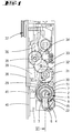
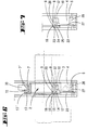
- FIG. 1 A lock according to the invention is shown in FIG. 1 with a locking mechanism.
- a locking mechanism is described in detail in German Offenlegungsschrift 41 10 556.
- the functioning and design of the transmission with the exception of the locking mechanism, reference is therefore made to the description of this laid-open specification 41 10 556.
- the lock gear consists of drive sprocket 5, which has a radial recess 4, in which the lock bit 3 of a lock cylinder 2 engages.
- the lock cylinder 2 is in an insertion opening 6 of the lock base 1.
- Adjacent to the drive sprocket 5 are two smaller driven gears 29 and 30 which mesh both with the driven sprocket 5 and with a peripheral toothing of a downstream gear 31.
- a smaller diameter ring gear of the gear 31 meshes with a ring gear of the gear 33, which drives a drive rod connecting slide 39 via a further gear 34, which also has a toothing in which a toothing of the gear 34 engages.
- the connecting rod connecting slide 39 interacts with connecting rods 40 which cooperate with closing elements arranged outside the lock.
- the lock itself has a latch 37 and a bolt 38 as locking elements.
- the trap can be shifted from the drive sprocket 5 via a change operation.
- the bolt is also shifted by a rotary movement of the drive sprocket 5 via a gear coupling.
- Triggers for the relocation of the said Locking elements, latch 37 and bolt 38, is the locking bit 3 of the locking cylinder 12, which engages in the radial opening 4 of the drive ring gear 5.
- the suitable key is inserted in the lock cylinder, for example, the bolt can be moved without a cylinder actuation due to the then possible release of the lock bit.
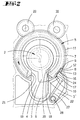
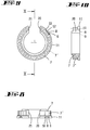
- the drive sprocket 5 consists of two segments 7 and 13 which are identical in shape in plan view. Both segments have a radial recess 4 which have identical widths. Of the two segments 7 and 13, only segment 7 is toothed. The segment 7 lies with the interposition of the segment 13 on the castle floor. The segment 7 is rotatable relative to the segment 13. That is, if the segment 7 is driven, for example, by gear elements as a result of tooth meshing of the gear wheels 29 or 30, then the segment 13 underneath does not rotate with it, but initially remains. The thickness of the two segments is selected so that both can be acted upon by the locking bit of the locking cylinder 2 inserted into the insertion opening 5 and are thus rotationally driven by the locking bit 3.
- the non-toothed peripheral region 11 of the first toothed segment 7 is larger in diameter than the toothing 7 '.
- the toothless area of the second segment faces the floor.
- the thickness of the toothless region 11 is less than the thickness of the toothing 7 '.
- the non-toothed peripheral region 11 has a cutout 8 which forms a blocking step 9 on one side and a ramp slope 10 on the other side.
- the ramp slope 10 and blocking step 9 are separated by a bottom surface 12 which extends in the circumferential direction.
- the segment 7 also has a radial slot, which is formed by the essentially parallel walls 20 and 21, the distance between the walls 20, 21 being greater than the thickness of a standardized locking cylinder lock bit 3.
- the second segment 13 is toothless and narrower in thickness than the first segment 7, but approximately as thick as the toothless region 11.
- the diameter of the segment 13 corresponds to the diameter of the toothless region 11 of the segment 7.
- the toothless region 13 'of segment 13 has a recess 14. This recess is arranged so that it is essentially aligned with the recess of segment 7 when the two segments are in alignment.
- the bottom 15 of the recess 14, however, is shorter in the circumferential direction than the bottom 12 of the recess 8.
- the recess 14 is delimited on both sides by a run-up slope 16 and 17.
- the run-up slope 16 of the blocking stage 9 is arranged in such a way that the blocking stage does not come into effect, with the locking lug 26 of a lever 22.
- the thickness of the locking lug of the lever 22 is chosen so that it both the toothless peripheral surface 11, as well as the toothless peripheral surface 13 '.
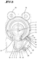
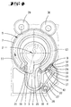
- the lever 22 is pivotally arranged about a fixed axis 28 in the lock housing and spring-loaded with a spring 27 in such a way that the end face 24 of the lever 22 grinds onto the peripheral surface 13 'or 11 of the segments 7, 13. As a result of the spring action, the end face 24 of the lever 22 can enter the cutouts 14 and 18. If the two segments 7, 13 are in alignment with one another, as shown in particular in FIGS. 2, 4, 5, the lever 22 with its locking edge 23 does not come into effect with the locking edge 9, but instead runs on the run-up slope 16 during a return movement on. The alignment of the two segments 7, 13 is always ensured when the drive sprocket 5 is acted upon by the locking bit 3 of the locking cylinder 2. The locking bit 3 then acts either simultaneously on the walls 19 and 21 of the radial recess in the segments 7, 13 or in the opposite closing direction on the walls 18 and 20 of the segments 7, 13.
- the two segments 7, 13 emerge from the aligned superimposed position due to relative rotation to one another.
- the gear position of a lock is shown, which is achieved after a yoke movement generated, for example, by applying force to the bolt.
- the ring gear 5 is shifted via the gear wheels 29 and 30.
- the two-part structure of the ring gear 5 means that only the first segment 7 is rotated due to the tooth engagement in this type of displacement.
- segment 1 initially remains relative to the castle floor. According to the Displacement of the segment occurs with the wall 20 of the radial recess against the locking member 3 of the locking cylinder 2.
- the displacement of the segment 7 can only take place until the locking lug 26 of the lever 22 abuts the locking step 9 with the locking edge 23.
- the end face 24 is immersed in the cutout 14 of the segment 13 and the run-up slope 16 has passed under the larger area of the circumferential surface 11, so that the blocking step 9 has stepped over the cutout 8. The return of the locking elements is blocked in this position.
- the locking cylinder is displaced, for example, in the direction of the arrow, that is to say in the direction of return, the locking bit 3 acts on the wall 19 of the segment 13.
- the segment 13 is displaced relative to the segment, with the bevel 16 the locking edge 23 of the locking nose 26 acted upon and thus the lever is moved radially to the drive sprocket 5 and thus disengages from the locking edge 9.
- the lock can be actuated again.
- the latter closed position is shown in particular in FIG. 4.
- the swivel lever 22 first acts on the locking bit 3 with its end face 24. Because of the rounded edge areas 3 'of the locking bit 3 and the rounded edge areas 27, 28 of the drive sprocket 5, no locking occurs at these edges . To prevent undesired locking, the rounded edge 25, which adjoins the locking edge 23 of the end face 24 of the locking lug 26, also bears.
Landscapes
- Engineering & Computer Science (AREA)
- Mechanical Engineering (AREA)
- Lock And Its Accessories (AREA)
- Fluid-Damping Devices (AREA)
- Prostheses (AREA)
- Mutual Connection Of Rods And Tubes (AREA)
- Pivots And Pivotal Connections (AREA)
- Control Of Fluid Gearings (AREA)
- Actuator (AREA)
- Chairs Characterized By Structure (AREA)
- Soil Working Implements (AREA)
Applications Claiming Priority (2)
| Application Number | Priority Date | Filing Date | Title |
|---|---|---|---|
| DE4323995 | 1993-07-17 | ||
| DE4323995A DE4323995A1 (de) | 1993-07-17 | 1993-07-17 | Schließzylinderbetätigbares Schloß mit Rücklaufsperre |
Publications (2)
| Publication Number | Publication Date |
|---|---|
| EP0637666A1 true EP0637666A1 (fr) | 1995-02-08 |
| EP0637666B1 EP0637666B1 (fr) | 1997-10-29 |
Family
ID=6493052
Family Applications (1)
| Application Number | Title | Priority Date | Filing Date |
|---|---|---|---|
| EP94107266A Expired - Lifetime EP0637666B1 (fr) | 1993-07-17 | 1994-05-10 | Serrure cylindrique avec dispositif anti-retour |
Country Status (6)
| Country | Link |
|---|---|
| EP (1) | EP0637666B1 (fr) |
| AT (1) | ATE159790T1 (fr) |
| DE (2) | DE4323995A1 (fr) |
| DK (1) | DK0637666T3 (fr) |
| ES (1) | ES2108328T3 (fr) |
| GR (1) | GR3025253T3 (fr) |
Cited By (2)
| Publication number | Priority date | Publication date | Assignee | Title |
|---|---|---|---|---|
| EP1536086A1 (fr) * | 2003-11-28 | 2005-06-01 | CISA S.p.A. | Serrure avec un dispositif pour empêcher toute erreur d'alignement de la roue dentée du dispositif de fermeture/ouverture pendant l'introduction du barillet à clé dans la serrure |
| EP2186974A1 (fr) * | 2008-11-14 | 2010-05-19 | Joseph Talpe | Verrou de cylindre avec boulon assemblé en pivot |
Families Citing this family (1)
| Publication number | Priority date | Publication date | Assignee | Title |
|---|---|---|---|---|
| DE102009006497B4 (de) | 2009-01-28 | 2014-08-21 | Dorma Gmbh + Co. Kg | Schloss, insbesondere Schubriegelschloss, mit erhöhter Schutzwirkung |
Citations (3)
| Publication number | Priority date | Publication date | Assignee | Title |
|---|---|---|---|---|
| DE3034764A1 (de) * | 1980-09-15 | 1982-03-25 | Gretsch-Unitas Gmbh Baubeschlagfabrik, 7257 Ditzingen | Sperrvorrichtung, insbesondere fuer ein schloss |
| EP0141891A1 (fr) * | 1983-11-09 | 1985-05-22 | FERCO INTERNATIONAL Usine de Ferrures de BÀ¢timent Société à responsabilité limitée | Crémone-serrure pour portes, portes-fenêtres ou analogues |
| DE4110556A1 (de) * | 1991-03-30 | 1992-10-08 | Fliether Karl Gmbh & Co | Mittels druecker und/oder schliesszylinder zu betaetigendes schloss |
-
1993
- 1993-07-17 DE DE4323995A patent/DE4323995A1/de not_active Withdrawn
-
1994
- 1994-05-10 AT AT94107266T patent/ATE159790T1/de not_active IP Right Cessation
- 1994-05-10 DK DK94107266T patent/DK0637666T3/da active
- 1994-05-10 DE DE59404458T patent/DE59404458D1/de not_active Expired - Lifetime
- 1994-05-10 EP EP94107266A patent/EP0637666B1/fr not_active Expired - Lifetime
- 1994-05-10 ES ES94107266T patent/ES2108328T3/es not_active Expired - Lifetime
-
1997
- 1997-11-05 GR GR970402890T patent/GR3025253T3/el unknown
Patent Citations (3)
| Publication number | Priority date | Publication date | Assignee | Title |
|---|---|---|---|---|
| DE3034764A1 (de) * | 1980-09-15 | 1982-03-25 | Gretsch-Unitas Gmbh Baubeschlagfabrik, 7257 Ditzingen | Sperrvorrichtung, insbesondere fuer ein schloss |
| EP0141891A1 (fr) * | 1983-11-09 | 1985-05-22 | FERCO INTERNATIONAL Usine de Ferrures de BÀ¢timent Société à responsabilité limitée | Crémone-serrure pour portes, portes-fenêtres ou analogues |
| DE4110556A1 (de) * | 1991-03-30 | 1992-10-08 | Fliether Karl Gmbh & Co | Mittels druecker und/oder schliesszylinder zu betaetigendes schloss |
Cited By (3)
| Publication number | Priority date | Publication date | Assignee | Title |
|---|---|---|---|---|
| EP1536086A1 (fr) * | 2003-11-28 | 2005-06-01 | CISA S.p.A. | Serrure avec un dispositif pour empêcher toute erreur d'alignement de la roue dentée du dispositif de fermeture/ouverture pendant l'introduction du barillet à clé dans la serrure |
| EP2186974A1 (fr) * | 2008-11-14 | 2010-05-19 | Joseph Talpe | Verrou de cylindre avec boulon assemblé en pivot |
| US8523247B2 (en) | 2008-11-14 | 2013-09-03 | Joseph Talpe | Cylinder lock with pivotally-mounted bolt |
Also Published As
| Publication number | Publication date |
|---|---|
| ES2108328T3 (es) | 1997-12-16 |
| DE59404458D1 (de) | 1997-12-04 |
| DE4323995A1 (de) | 1995-01-19 |
| GR3025253T3 (en) | 1998-02-27 |
| DK0637666T3 (da) | 1998-07-20 |
| ATE159790T1 (de) | 1997-11-15 |
| EP0637666B1 (fr) | 1997-10-29 |
Similar Documents
| Publication | Publication Date | Title |
|---|---|---|
| EP0722029B1 (fr) | Serrure de portière à système de verrouillage central rotatoire | |
| DE69007620T2 (de) | Elektrisch und mechanisch betätigbarer schlossmechanismus. | |
| DE3447748C2 (fr) | ||
| DE4327782C2 (de) | Türverschlußvorrichtung mit einem Ein-Bewegungs-Türöffnungsmechanismus | |
| DE4327781C2 (de) | Überverschlußmechanismus einer Fahrzeugtürverschlußvorrichtung | |
| EP2010739B1 (fr) | Fermeture de portière de véhicule à moteur | |
| DE4325693C2 (de) | Türschließeinrichtung | |
| EP0007395A1 (fr) | Serrure pour portes à serrure cylindrique actionnée par une clé | |
| DE102004061487A1 (de) | Motor-getriebene Lenkradschlosseinrichtung | |
| DE69506222T2 (de) | Treibstangenverschluss für ein fenster oder eine tuer | |
| DE19845125A1 (de) | Fahrzeugtürverriegelungsvorrichtung mit Selbstrückstellmechanismus | |
| EP2752537A2 (fr) | Agencement de ferrure | |
| EP0637666B1 (fr) | Serrure cylindrique avec dispositif anti-retour | |
| EP1885977A1 (fr) | Dispositif de verrou de securite pour une porte, un portail ou un element similaire | |
| DE3034764A1 (de) | Sperrvorrichtung, insbesondere fuer ein schloss | |
| EP1671001B1 (fr) | Serrure | |
| DE4407912A1 (de) | Elektromechanisches Schloß | |
| DE2727601A1 (de) | Schliessvorrichtung | |
| DE2531727A1 (de) | Schliessvorrichtung | |
| DE19628010C2 (de) | Vorrichtung zur Verstellung der Schubstange einer Riegelwerks | |
| DE29909660U1 (de) | Türverschluß | |
| DE19526660A1 (de) | Elektromechanisches Schloß | |
| EP0491133A1 (fr) | Mécanisme d'actionnement pour serrures de fenêtres et portes ou similaire | |
| DE102021103622A1 (de) | Dreh-getriebeanordnung zur vergrösserung des hartanschlag-motorweges | |
| DE19628012C2 (de) | Ausfahrsperre für die Riegel eines Riegelwerks |
Legal Events
| Date | Code | Title | Description |
|---|---|---|---|
| PUAI | Public reference made under article 153(3) epc to a published international application that has entered the european phase |
Free format text: ORIGINAL CODE: 0009012 |
|
| AK | Designated contracting states |
Kind code of ref document: A1 Designated state(s): AT BE CH DE DK ES FR GB GR IE IT LI LU MC NL PT SE |
|
| 17P | Request for examination filed |
Effective date: 19950714 |
|
| 17Q | First examination report despatched |
Effective date: 19970127 |
|
| GRAG | Despatch of communication of intention to grant |
Free format text: ORIGINAL CODE: EPIDOS AGRA |
|
| GRAH | Despatch of communication of intention to grant a patent |
Free format text: ORIGINAL CODE: EPIDOS IGRA |
|
| GRAH | Despatch of communication of intention to grant a patent |
Free format text: ORIGINAL CODE: EPIDOS IGRA |
|
| GRAA | (expected) grant |
Free format text: ORIGINAL CODE: 0009210 |
|
| AK | Designated contracting states |
Kind code of ref document: B1 Designated state(s): AT BE CH DE DK ES FR GB GR IE IT LI LU MC NL PT SE |
|
| REF | Corresponds to: |
Ref document number: 159790 Country of ref document: AT Date of ref document: 19971115 Kind code of ref document: T |
|
| REG | Reference to a national code |
Ref country code: CH Ref legal event code: NV Representative=s name: R. A. EGLI & CO. PATENTANWAELTE Ref country code: CH Ref legal event code: EP |
|
| GBT | Gb: translation of ep patent filed (gb section 77(6)(a)/1977) |
Effective date: 19971031 |
|
| REF | Corresponds to: |
Ref document number: 59404458 Country of ref document: DE Date of ref document: 19971204 |
|
| REG | Reference to a national code |
Ref country code: ES Ref legal event code: FG2A Ref document number: 2108328 Country of ref document: ES Kind code of ref document: T3 |
|
| ET | Fr: translation filed | ||
| ITF | It: translation for a ep patent filed | ||
| PG25 | Lapsed in a contracting state [announced via postgrant information from national office to epo] |
Ref country code: SE Effective date: 19980129 Ref country code: PT Free format text: LAPSE BECAUSE OF FAILURE TO SUBMIT A TRANSLATION OF THE DESCRIPTION OR TO PAY THE FEE WITHIN THE PRESCRIBED TIME-LIMIT Effective date: 19980129 |
|
| REG | Reference to a national code |
Ref country code: GR Ref legal event code: FG4A Free format text: 3025253 |
|
| PGFP | Annual fee paid to national office [announced via postgrant information from national office to epo] |
Ref country code: MC Payment date: 19980430 Year of fee payment: 5 |
|
| PG25 | Lapsed in a contracting state [announced via postgrant information from national office to epo] |
Ref country code: LU Free format text: LAPSE BECAUSE OF NON-PAYMENT OF DUE FEES Effective date: 19980510 |
|
| PGFP | Annual fee paid to national office [announced via postgrant information from national office to epo] |
Ref country code: GR Payment date: 19980529 Year of fee payment: 5 |
|
| REG | Reference to a national code |
Ref country code: DK Ref legal event code: T3 |
|
| PLBE | No opposition filed within time limit |
Free format text: ORIGINAL CODE: 0009261 |
|
| STAA | Information on the status of an ep patent application or granted ep patent |
Free format text: STATUS: NO OPPOSITION FILED WITHIN TIME LIMIT |
|
| 26N | No opposition filed | ||
| PG25 | Lapsed in a contracting state [announced via postgrant information from national office to epo] |
Ref country code: GR Free format text: LAPSE BECAUSE OF NON-PAYMENT OF DUE FEES Effective date: 19990531 |
|
| PG25 | Lapsed in a contracting state [announced via postgrant information from national office to epo] |
Ref country code: MC Free format text: LAPSE BECAUSE OF NON-PAYMENT OF DUE FEES Effective date: 19991130 |
|
| REG | Reference to a national code |
Ref country code: GB Ref legal event code: IF02 |
|
| PGFP | Annual fee paid to national office [announced via postgrant information from national office to epo] |
Ref country code: ES Payment date: 20080522 Year of fee payment: 15 Ref country code: DK Payment date: 20080526 Year of fee payment: 15 Ref country code: CH Payment date: 20080526 Year of fee payment: 15 |
|
| PGFP | Annual fee paid to national office [announced via postgrant information from national office to epo] |
Ref country code: AT Payment date: 20080521 Year of fee payment: 15 |
|
| PGFP | Annual fee paid to national office [announced via postgrant information from national office to epo] |
Ref country code: BE Payment date: 20080526 Year of fee payment: 15 Ref country code: IT Payment date: 20080520 Year of fee payment: 15 |
|
| PGFP | Annual fee paid to national office [announced via postgrant information from national office to epo] |
Ref country code: NL Payment date: 20080528 Year of fee payment: 15 Ref country code: IE Payment date: 20080526 Year of fee payment: 15 |
|
| PGFP | Annual fee paid to national office [announced via postgrant information from national office to epo] |
Ref country code: FR Payment date: 20080521 Year of fee payment: 15 |
|
| PGFP | Annual fee paid to national office [announced via postgrant information from national office to epo] |
Ref country code: GB Payment date: 20080520 Year of fee payment: 15 |
|
| BERE | Be: lapsed |
Owner name: KARL *FLIETHER G.M.B.H. & CO. Effective date: 20090531 |
|
| REG | Reference to a national code |
Ref country code: CH Ref legal event code: PL |
|
| REG | Reference to a national code |
Ref country code: DK Ref legal event code: EBP |
|
| GBPC | Gb: european patent ceased through non-payment of renewal fee |
Effective date: 20090510 |
|
| PG25 | Lapsed in a contracting state [announced via postgrant information from national office to epo] |
Ref country code: LI Free format text: LAPSE BECAUSE OF NON-PAYMENT OF DUE FEES Effective date: 20090531 Ref country code: CH Free format text: LAPSE BECAUSE OF NON-PAYMENT OF DUE FEES Effective date: 20090531 Ref country code: AT Free format text: LAPSE BECAUSE OF NON-PAYMENT OF DUE FEES Effective date: 20090510 |
|
| NLV4 | Nl: lapsed or anulled due to non-payment of the annual fee |
Effective date: 20091201 |
|
| PG25 | Lapsed in a contracting state [announced via postgrant information from national office to epo] |
Ref country code: NL Free format text: LAPSE BECAUSE OF NON-PAYMENT OF DUE FEES Effective date: 20091201 |
|
| REG | Reference to a national code |
Ref country code: FR Ref legal event code: ST Effective date: 20100129 |
|
| REG | Reference to a national code |
Ref country code: IE Ref legal event code: MM4A |
|
| PG25 | Lapsed in a contracting state [announced via postgrant information from national office to epo] |
Ref country code: IE Free format text: LAPSE BECAUSE OF NON-PAYMENT OF DUE FEES Effective date: 20090511 Ref country code: FR Free format text: LAPSE BECAUSE OF NON-PAYMENT OF DUE FEES Effective date: 20090602 Ref country code: DK Free format text: LAPSE BECAUSE OF NON-PAYMENT OF DUE FEES Effective date: 20090531 |
|
| PG25 | Lapsed in a contracting state [announced via postgrant information from national office to epo] |
Ref country code: GB Free format text: LAPSE BECAUSE OF NON-PAYMENT OF DUE FEES Effective date: 20090510 |
|
| PG25 | Lapsed in a contracting state [announced via postgrant information from national office to epo] |
Ref country code: BE Free format text: LAPSE BECAUSE OF NON-PAYMENT OF DUE FEES Effective date: 20090531 |
|
| REG | Reference to a national code |
Ref country code: ES Ref legal event code: FD2A Effective date: 20090511 |
|
| PGFP | Annual fee paid to national office [announced via postgrant information from national office to epo] |
Ref country code: DE Payment date: 20100602 Year of fee payment: 17 |
|
| PG25 | Lapsed in a contracting state [announced via postgrant information from national office to epo] |
Ref country code: ES Free format text: LAPSE BECAUSE OF NON-PAYMENT OF DUE FEES Effective date: 20090511 |
|
| PG25 | Lapsed in a contracting state [announced via postgrant information from national office to epo] |
Ref country code: IT Free format text: LAPSE BECAUSE OF NON-PAYMENT OF DUE FEES Effective date: 20090510 |
|
| REG | Reference to a national code |
Ref country code: DE Ref legal event code: R119 Ref document number: 59404458 Country of ref document: DE |
|
| REG | Reference to a national code |
Ref country code: DE Ref legal event code: R119 Ref document number: 59404458 Country of ref document: DE |
|
| PG25 | Lapsed in a contracting state [announced via postgrant information from national office to epo] |
Ref country code: DE Free format text: LAPSE BECAUSE OF NON-PAYMENT OF DUE FEES Effective date: 20111130 |