EP0637672B1 - Verglasung mit Drei oder mehr Glasscheiben mit niedriger Wärmeübertragung am Rand und sein Herstellungsverfahren - Google Patents
Verglasung mit Drei oder mehr Glasscheiben mit niedriger Wärmeübertragung am Rand und sein Herstellungsverfahren Download PDFInfo
- Publication number
- EP0637672B1 EP0637672B1 EP94111939A EP94111939A EP0637672B1 EP 0637672 B1 EP0637672 B1 EP 0637672B1 EP 94111939 A EP94111939 A EP 94111939A EP 94111939 A EP94111939 A EP 94111939A EP 0637672 B1 EP0637672 B1 EP 0637672B1
- Authority
- EP
- European Patent Office
- Prior art keywords
- spacer
- sheets
- unit
- sheet
- portions
- Prior art date
- Legal status (The legal status is an assumption and is not a legal conclusion. Google has not performed a legal analysis and makes no representation as to the accuracy of the status listed.)
- Expired - Lifetime
Links
- 239000011521 glass Substances 0.000 title claims description 63
- 238000004519 manufacturing process Methods 0.000 title claims description 9
- 239000000463 material Substances 0.000 claims abstract description 112
- 238000007493 shaping process Methods 0.000 claims abstract description 9
- 125000006850 spacer group Chemical group 0.000 claims description 157
- 239000000853 adhesive Substances 0.000 claims description 29
- 230000001070 adhesive effect Effects 0.000 claims description 29
- 238000000034 method Methods 0.000 claims description 29
- 239000000758 substrate Substances 0.000 claims description 28
- 230000002093 peripheral effect Effects 0.000 claims description 18
- 238000000576 coating method Methods 0.000 claims description 16
- 230000009969 flowable effect Effects 0.000 claims description 15
- 239000002274 desiccant Substances 0.000 claims description 13
- 239000011248 coating agent Substances 0.000 claims description 11
- 239000000565 sealant Substances 0.000 claims description 11
- 239000011324 bead Substances 0.000 claims description 10
- 238000005452 bending Methods 0.000 claims description 5
- 230000007613 environmental effect Effects 0.000 claims description 5
- 238000010438 heat treatment Methods 0.000 claims description 2
- 238000007789 sealing Methods 0.000 claims 1
- 238000000151 deposition Methods 0.000 abstract 1
- 239000010410 layer Substances 0.000 description 64
- 239000007789 gas Substances 0.000 description 30
- XKRFYHLGVUSROY-UHFFFAOYSA-N Argon Chemical compound [Ar] XKRFYHLGVUSROY-UHFFFAOYSA-N 0.000 description 12
- 239000002184 metal Substances 0.000 description 12
- 229910052751 metal Inorganic materials 0.000 description 12
- 239000012790 adhesive layer Substances 0.000 description 11
- 239000004033 plastic Substances 0.000 description 8
- 229920003023 plastic Polymers 0.000 description 8
- 229910052786 argon Inorganic materials 0.000 description 6
- 125000000484 butyl group Chemical group [H]C([*])([H])C([H])([H])C([H])([H])C([H])([H])[H] 0.000 description 6
- 229910000831 Steel Inorganic materials 0.000 description 5
- 238000001125 extrusion Methods 0.000 description 5
- 239000010959 steel Substances 0.000 description 5
- 230000003750 conditioning effect Effects 0.000 description 4
- 238000009792 diffusion process Methods 0.000 description 3
- 239000012943 hotmelt Substances 0.000 description 3
- 230000035699 permeability Effects 0.000 description 3
- 238000005086 pumping Methods 0.000 description 3
- 229910001220 stainless steel Inorganic materials 0.000 description 3
- 229920002367 Polyisobutene Polymers 0.000 description 2
- ATJFFYVFTNAWJD-UHFFFAOYSA-N Tin Chemical compound [Sn] ATJFFYVFTNAWJD-UHFFFAOYSA-N 0.000 description 2
- 238000004590 computer program Methods 0.000 description 2
- 230000007423 decrease Effects 0.000 description 2
- 230000003247 decreasing effect Effects 0.000 description 2
- 230000000694 effects Effects 0.000 description 2
- 229920005862 polyol Polymers 0.000 description 2
- 150000003077 polyols Chemical class 0.000 description 2
- 229920001451 polypropylene glycol Polymers 0.000 description 2
- 229920002635 polyurethane Polymers 0.000 description 2
- 239000004814 polyurethane Substances 0.000 description 2
- 238000012546 transfer Methods 0.000 description 2
- 239000002023 wood Substances 0.000 description 2
- 239000004831 Hot glue Substances 0.000 description 1
- 229920001328 Polyvinylidene chloride Polymers 0.000 description 1
- 238000010521 absorption reaction Methods 0.000 description 1
- 229910052782 aluminium Inorganic materials 0.000 description 1
- XAGFODPZIPBFFR-UHFFFAOYSA-N aluminium Chemical compound [Al] XAGFODPZIPBFFR-UHFFFAOYSA-N 0.000 description 1
- 238000004458 analytical method Methods 0.000 description 1
- 239000011230 binding agent Substances 0.000 description 1
- 238000004364 calculation method Methods 0.000 description 1
- 238000013461 design Methods 0.000 description 1
- 238000011161 development Methods 0.000 description 1
- 230000008030 elimination Effects 0.000 description 1
- 238000003379 elimination reaction Methods 0.000 description 1
- 238000003780 insertion Methods 0.000 description 1
- 230000037431 insertion Effects 0.000 description 1
- 239000011159 matrix material Substances 0.000 description 1
- 238000005259 measurement Methods 0.000 description 1
- 230000035515 penetration Effects 0.000 description 1
- 239000005033 polyvinylidene chloride Substances 0.000 description 1
- 238000003892 spreading Methods 0.000 description 1
- 239000010935 stainless steel Substances 0.000 description 1
- 238000003860 storage Methods 0.000 description 1
- 238000002076 thermal analysis method Methods 0.000 description 1
Images


Classifications
-
- E—FIXED CONSTRUCTIONS
- E06—DOORS, WINDOWS, SHUTTERS, OR ROLLER BLINDS IN GENERAL; LADDERS
- E06B—FIXED OR MOVABLE CLOSURES FOR OPENINGS IN BUILDINGS, VEHICLES, FENCES OR LIKE ENCLOSURES IN GENERAL, e.g. DOORS, WINDOWS, BLINDS, GATES
- E06B3/00—Window sashes, door leaves, or like elements for closing wall or like openings; Layout of fixed or moving closures, e.g. windows in wall or like openings; Features of rigidly-mounted outer frames relating to the mounting of wing frames
- E06B3/66—Units comprising two or more parallel glass or like panes permanently secured together
- E06B3/663—Elements for spacing panes
- E06B3/66309—Section members positioned at the edges of the glazing unit
- E06B3/66366—Section members positioned at the edges of the glazing unit specially adapted for units comprising more than two panes or for attaching intermediate sheets
-
- B—PERFORMING OPERATIONS; TRANSPORTING
- B29—WORKING OF PLASTICS; WORKING OF SUBSTANCES IN A PLASTIC STATE IN GENERAL
- B29C—SHAPING OR JOINING OF PLASTICS; SHAPING OF MATERIAL IN A PLASTIC STATE, NOT OTHERWISE PROVIDED FOR; AFTER-TREATMENT OF THE SHAPED PRODUCTS, e.g. REPAIRING
- B29C48/00—Extrusion moulding, i.e. expressing the moulding material through a die or nozzle which imparts the desired form; Apparatus therefor
- B29C48/03—Extrusion moulding, i.e. expressing the moulding material through a die or nozzle which imparts the desired form; Apparatus therefor characterised by the shape of the extruded material at extrusion
- B29C48/05—Filamentary, e.g. strands
-
- B—PERFORMING OPERATIONS; TRANSPORTING
- B29—WORKING OF PLASTICS; WORKING OF SUBSTANCES IN A PLASTIC STATE IN GENERAL
- B29C—SHAPING OR JOINING OF PLASTICS; SHAPING OF MATERIAL IN A PLASTIC STATE, NOT OTHERWISE PROVIDED FOR; AFTER-TREATMENT OF THE SHAPED PRODUCTS, e.g. REPAIRING
- B29C48/00—Extrusion moulding, i.e. expressing the moulding material through a die or nozzle which imparts the desired form; Apparatus therefor
- B29C48/25—Component parts, details or accessories; Auxiliary operations
- B29C48/30—Extrusion nozzles or dies
- B29C48/345—Extrusion nozzles comprising two or more adjacently arranged ports, for simultaneously extruding multiple strands, e.g. for pelletising
-
- E—FIXED CONSTRUCTIONS
- E06—DOORS, WINDOWS, SHUTTERS, OR ROLLER BLINDS IN GENERAL; LADDERS
- E06B—FIXED OR MOVABLE CLOSURES FOR OPENINGS IN BUILDINGS, VEHICLES, FENCES OR LIKE ENCLOSURES IN GENERAL, e.g. DOORS, WINDOWS, BLINDS, GATES
- E06B3/00—Window sashes, door leaves, or like elements for closing wall or like openings; Layout of fixed or moving closures, e.g. windows in wall or like openings; Features of rigidly-mounted outer frames relating to the mounting of wing frames
- E06B3/66—Units comprising two or more parallel glass or like panes permanently secured together
- E06B3/673—Assembling the units
- E06B3/67304—Preparing rigid spacer members before assembly
- E06B3/67308—Making spacer frames, e.g. by bending or assembling straight sections
- E06B3/67313—Making spacer frames, e.g. by bending or assembling straight sections by bending
-
- E—FIXED CONSTRUCTIONS
- E06—DOORS, WINDOWS, SHUTTERS, OR ROLLER BLINDS IN GENERAL; LADDERS
- E06B—FIXED OR MOVABLE CLOSURES FOR OPENINGS IN BUILDINGS, VEHICLES, FENCES OR LIKE ENCLOSURES IN GENERAL, e.g. DOORS, WINDOWS, BLINDS, GATES
- E06B3/00—Window sashes, door leaves, or like elements for closing wall or like openings; Layout of fixed or moving closures, e.g. windows in wall or like openings; Features of rigidly-mounted outer frames relating to the mounting of wing frames
- E06B3/66—Units comprising two or more parallel glass or like panes permanently secured together
- E06B3/673—Assembling the units
- E06B3/67304—Preparing rigid spacer members before assembly
- E06B3/67321—Covering spacer elements, e.g. with sealants
-
- E—FIXED CONSTRUCTIONS
- E06—DOORS, WINDOWS, SHUTTERS, OR ROLLER BLINDS IN GENERAL; LADDERS
- E06B—FIXED OR MOVABLE CLOSURES FOR OPENINGS IN BUILDINGS, VEHICLES, FENCES OR LIKE ENCLOSURES IN GENERAL, e.g. DOORS, WINDOWS, BLINDS, GATES
- E06B3/00—Window sashes, door leaves, or like elements for closing wall or like openings; Layout of fixed or moving closures, e.g. windows in wall or like openings; Features of rigidly-mounted outer frames relating to the mounting of wing frames
- E06B3/66—Units comprising two or more parallel glass or like panes permanently secured together
- E06B3/677—Evacuating or filling the gap between the panes ; Equilibration of inside and outside pressure; Preventing condensation in the gap between the panes; Cleaning the gap between the panes
- E06B3/6775—Evacuating or filling the gap during assembly
-
- B—PERFORMING OPERATIONS; TRANSPORTING
- B29—WORKING OF PLASTICS; WORKING OF SUBSTANCES IN A PLASTIC STATE IN GENERAL
- B29C—SHAPING OR JOINING OF PLASTICS; SHAPING OF MATERIAL IN A PLASTIC STATE, NOT OTHERWISE PROVIDED FOR; AFTER-TREATMENT OF THE SHAPED PRODUCTS, e.g. REPAIRING
- B29C48/00—Extrusion moulding, i.e. expressing the moulding material through a die or nozzle which imparts the desired form; Apparatus therefor
- B29C48/03—Extrusion moulding, i.e. expressing the moulding material through a die or nozzle which imparts the desired form; Apparatus therefor characterised by the shape of the extruded material at extrusion
-
- B—PERFORMING OPERATIONS; TRANSPORTING
- B29—WORKING OF PLASTICS; WORKING OF SUBSTANCES IN A PLASTIC STATE IN GENERAL
- B29C—SHAPING OR JOINING OF PLASTICS; SHAPING OF MATERIAL IN A PLASTIC STATE, NOT OTHERWISE PROVIDED FOR; AFTER-TREATMENT OF THE SHAPED PRODUCTS, e.g. REPAIRING
- B29C48/00—Extrusion moulding, i.e. expressing the moulding material through a die or nozzle which imparts the desired form; Apparatus therefor
- B29C48/03—Extrusion moulding, i.e. expressing the moulding material through a die or nozzle which imparts the desired form; Apparatus therefor characterised by the shape of the extruded material at extrusion
- B29C48/07—Flat, e.g. panels
- B29C48/08—Flat, e.g. panels flexible, e.g. films
-
- E—FIXED CONSTRUCTIONS
- E06—DOORS, WINDOWS, SHUTTERS, OR ROLLER BLINDS IN GENERAL; LADDERS
- E06B—FIXED OR MOVABLE CLOSURES FOR OPENINGS IN BUILDINGS, VEHICLES, FENCES OR LIKE ENCLOSURES IN GENERAL, e.g. DOORS, WINDOWS, BLINDS, GATES
- E06B3/00—Window sashes, door leaves, or like elements for closing wall or like openings; Layout of fixed or moving closures, e.g. windows in wall or like openings; Features of rigidly-mounted outer frames relating to the mounting of wing frames
- E06B3/66—Units comprising two or more parallel glass or like panes permanently secured together
- E06B3/663—Elements for spacing panes
- E06B3/66309—Section members positioned at the edges of the glazing unit
- E06B2003/66395—U-shape
Definitions
- This invention relates to a unit having three or more sheets, and, in particular to a triple unit having a pair of outer sheets separated by an edge assembly, the edge assembly including a spacer arrangement for supporting a sheet between the outer sheets, and method of making of the triple unit.
- the triple glazed unit includes a pair of outer glass sheets separated by a spacer-dehydrator element, or metal spacer, having a groove to maintain a third glass sheet between the outer two glass sheets.
- a layer of a flowable, pliable material has a generally U-shape cross section to provide a groove to receive marginal edge portions of the third or intermediate sheet.
- Facilities are provided to maintain the intermediate sheet in a substantially fixed relationship to the outer sheets.
- the wall portions of the spacer at selected corners of the finished unit are bent toward one another and spaced a sufficient distance to receive the intermediate sheet therebetween. The wall portions of the spacer bent toward one another biases the pliable material on the receiving surface of the spacer toward the intermediate sheet to maintain the intermediate sheet in position.
- the configuration of the spacer is not limiting to the invention and may have any cross section provided it has a surface to receive the shaped layer 38 and the intermediate glass sheet 26.
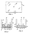
- a unit 50 having the glass sheets 22 and 24 separated by an edge assembly 52 having the adhesive layers 32 to secure the glass sheets 22 and 24 to spacer 54.
- the spacer 54 may be made of wood, metal or plastic having any cross sectional configuration and a receiving surface 56 to receive the shaped layer 38 in a similar fashion as the surface 40 of the spacer 30 of the edge assembly 28 shown in Fig. 2.
- the adhesive layer 32 or sealant layer 32 be thin and long to reduce the diffusion of the insulating gas out of the compartments of the unit or atmosphere's gas into the compartments of the unit. More particularly, increasing the thickness of the layer 32 i.e. the distance between the glass sheet and the adjacent leg of the spacer while keeping all other conditions constant increases the diffusion rate, and increasing the length of the layer 32 i.e. the distance between the top of the outer leg of the spacer and the peripheral edge of the sheets or the outer surface 46 of the spacer 30 as viewed in Fig. 2 while keeping all other conditions constant decreases the diffusion rate of gas through the adhesive layer 32.
- the invention may be practiced with the adhesive layer 32 having a thickness less than about 0.125 inch (0.32 cm) and more particularly, of about 0.005 inch (0.013 cm) to about 0.125 inch (0.32 cm), preferably about 0.010 inch (0.025 cm) to about 0.020 inch (0.050 cm) and most preferably about 0.015 inch (0.38 cm), and a height of greater than about 0.010 inch (0.025 cm), and more particularly, of about 0.010 inch (0.025 cm) to about 0.50 inch (1.27 cm), preferably about 0.125 inch (0.32 cm) to about 0.50 inch (1.27 cm) and most preferably about 0.200 inch (0.50 cm).
- the spacer 30 should also be made of a material that is moisture and/or gas impervious e.g. metal or plastic of the type disclosed in The EP Application such as but not limited to metal coated steels, stainless steel, gas pervious spacers covered with a metal or polyvinylidene chloride film and/or a halogenated polymeric material.
- a material that is moisture and/or gas impervious e.g. metal or plastic of the type disclosed in The EP Application such as but not limited to metal coated steels, stainless steel, gas pervious spacers covered with a metal or polyvinylidene chloride film and/or a halogenated polymeric material.
- materials that are most preferably used in the practice of the invention are those materials that are flowable and remain pliable after flowing and materials that are flowable and harden e.g. are dimensionally stable after flowing.
- pliable materials means materials that have a Shore A Hardness of less than 45 after 10 seconds under load.
- Pliable materials that may be used in the practice of the invention have a Shore A Hardness of less than 40 after 10 seconds.
- Pliable materials used in the practice of the invention had a Shore A Hardness of 25 with a range of 20-30 after 10 seconds.
- hardened material is a material other than a pliable material.
- the material should be a moisture pervious material.
- materials having a permeability greater than 2 gm mm/M 2 day as determined by the above reference to ASTM F 372-73 are recommended in the practice of the invention.
- a unit similar to the unit 20 shown in Figs. 1 and 2 was made having rectangular shaped coated, clear glass sheets 22, 24 and uncoated, clear glass sheet 26.
- Each of the outer glass sheets 22 and 24 had a length of about 42-7/8 inches (108.9 cm) and a width of about 19-3/4 inches (50.17 cm).
- the intermediate sheet had a length of about 42-1/2 inches (107.95 cm) and a width of about 19-3/8 inches (49.2 cm).
- a spacer having four continuous corners was made as follows. With reference to Fig. 4, a flat tin coated steel strip 70 has a length of about 126 inches (320 cm), a width of about 1.30 inches (3.302 cm) and thickness of about 0.010 inch (0.25 mm) with a tapered and swedged end 72 having a hole 74. Opposite end 76 has a hole 78 and receives the end 72 when the spacer is positioned around the intermediate sheet.
- the taped end 72 had a length of about 1-1/2 inch (3.81 cm).
- the substrate is shaped to provide the spacer 30 with the U-shaped cross section.
- the ends of the upright legs 34 and 36 are radiused inwardly to provide stability to the spacer e.g. to reduce flexing of the spacer 30 prior to bending it around the glass sheet 26.
- the shaped layer 38 were provided by extruding H. B. Fuller HL-5102-X-125 butyl hot melt matrix having a desiccant therein is flowed onto the base of the spacer in using a nozzle arrangement to be discussed below incorporating features of the invention.
- the invention is not limited to the equipment for providing the shaped layer 38.
- Each of the raised portions of the shaped layer 38 had a height of 0.125 inch (0.32 cm) and a width of 0.255 inch (0.64 cm) to provide a groove having a depth of 0.093 inch (0.23 cm) and a width of 0.125 inch (0.32 cm). It is preferred to have the material of the layer 38 under the sheet to eliminate any contact between the sheet and the base of the spacer to prevent damage to the edge of the sheet.
- the shaped layer 38 may be extruded onto the base of the spacer before, after, or during the extrusion of the layers 32 onto the side of the spacer.
- the intermediate sheet 26 was positioned in the groove 48 of the shaped layer 38 between the pair of notches 82 and 84.
- the spacer between the pair of notches 84 and 86 was bent to position the groove 48 of the layer 38 between the notches 84 and 86 about the edge of the sheet; the spacer between the pair of notches 86 and the end 76 was bent to position the sheet in the groove 48 of the layer 38 therebetween.
- the tapered end 72 was bent to a 90 ° angle, and the spacer was bent to position the groove 48 of the spacer layer 38 between the pair of notches 80 and 82 about the intermediate sheet.
- the tapered end 72 was telescoped into the end 76 of the spacer. As the spacer was positioned about the glass sheet 26, the bent portions 58 at the corners moved the adhesive of the shaped layer 38 toward the corner of the glass sheet 26 as previously discussed.
- the holes 74 and 78 in the substrate for the unit made were aligned with each and with the edge of the intermediate sheet. Therefore the hole was sealed with polyol polyisobutylene and sealed over with the adhesive layer 44.
- the hole or holes shown in Fig. 4 as dotted lines 92
- the polyol polyisobutylene is not required to seal the compartment.
- nozzle arrangement 100 having a conditioning chamber 102 and a nozzle 104 secured thereto in any convenient manner e.g. by screws.
- the conditioning chamber 102 is connected by hose or conduit 106 to a supply of the adhesive material (not shown).
- the conditioning chamber 102 is provided with heating elements to heat the adhesive to its flow temperature; in the instance where the adhesive is a two component adhesive, the adhesive is mixed in the conditioning chamber 102.
- the slope surface 120 starts at the edge of the platform 110 and terminates about 0.125 inch (0.37 cm) therefrom.
- the tip 114 at the sloped end 118 has a height of about 0.080 inch (0.20 cm) and at the narrow end 116 of about 0.065 inch (0.165 cm).
- the holes 124 in the platform each had a diameter of about 0.120 inch (0.3 cm) and the hole 126 in the tip had a diameter of about 0.093 inch (0.236 cm).
- H. B. Fuller adhesive HL-5102-X-125 having a desiccant therein is heated to about 250°F (121°C).
- the platform 110 is positioned between the outer legs 34 and 36 of the spacer with the highest portion of the tip 114 e.g. end 118 of the tip spaced about 1/32 inch (0.08 cm) from the base 42 of the spacer 30.
- the sloped end 120 urges the leading edge of the spacer downward, if lifted, toward the conveyor as adhesive is extruded from the holes 124 and 126 to provide the shaped layer 38.
- the narrow portion of the tip and the step of the tip prevent tailing of the adhesive when the flowing e.g. pumping or extrusion of the material is stopped. It is expected that providing a step for the platform 110 similar to that of the tip will further ensure elimination of tailing.
- strings of adhesive are pulled.
- an insulating unit e.g. the unit 20 shown in Figs. 1 and 2 has an insulating gas between adjacent glass sheets 22, 26 and 26, 24, the insulating gas may be flowed into the compartment between the glass sheets in any convenient manner.
- injector arrangement 150 that may be used to move an insulating gas into a compartment while removing air in the compartment through a single spacer hole.
- the injector arrangement 150 includes a spring biased bifurated member 152 having outer legs 154 and 156 connected to a base 158.
- the spring member 152 is made of spring metal such that the legs 154 and 156 are spring biased toward one another to engage the glazing unit in a manner discussed below.
- the member 152 used in the practice of the invention was a binder clip.
- An inner tube 160 has an enlarged end 162 mounted in a housing 164 and passes through the housing.
- the tube 160 extends beyond the housing and outer tube 166 and is shown in Fig. 11 as end 168.
- the end 168 of the tube 160 is sized for insertion through the base 42 of the spacer 30 (see Fig. 2).
- the housing 164 has a hole 170 that provides access to the hollow interior of the housing.
- the outer tube 166 has end connected to the housing 164 and has external threads thereon.
- the housing arrangement is secured to the base 158 of the member 152 by passing the outer tube through a hole (not shown) in the base 158.
- a nut 172 threaded on the outer tube 166 engages O rings 174 on each side of the base 158 about the tube 166 to capture the base between the housing 164, the O rings 174 and the nuts 172 as shown in Fig. 11.
- the end 162 of the inner tube 160 is connected to an Argon supply (not shown), and the injector arrangement clamped to the unit by spreading the legs 154 and 156 apart by urging members 180 and 182 toward one another and inserting the end 168 of the inner tube 160 in a hole (not shown) in the spacer e.g. aligned holes in the substrate 70.
- the members 180 and 182 are released to clamp the nozzle arrangement 152 on the edge of a unit as shown in Fig. 12. It is recommended that the clamp engage the glass at the edge assembly of the unit e.g. edge assembly 28 of the unit 20 shown in Fig. 2, to prevent damage to the glass.
- one nozzle centrally located as shown in Fig. 12 is preferred.
- one nozzle may be used for each compartment or a nozzle arrangement having two nozzles may be used e.g. nozzle arrangement 194 shown in Fig. 13.
- the invention is not limited to making a triple glazed unit.
- a unit 200 having four glass sheets 22, 24 and 202.
- a blank or spacer 204 may be used between glass sheets 202 shown in Fig. 14.
- the intermediate sheet may have a hole drilled therein to interconnect the compartments of the triple glazed unit.
Landscapes
- Engineering & Computer Science (AREA)
- Civil Engineering (AREA)
- Structural Engineering (AREA)
- Mechanical Engineering (AREA)
- Manufacturing & Machinery (AREA)
- Securing Of Glass Panes Or The Like (AREA)
- Joining Of Glass To Other Materials (AREA)
- Laminated Bodies (AREA)
- Nozzles (AREA)
- Extrusion Moulding Of Plastics Or The Like (AREA)
- Re-Forming, After-Treatment, Cutting And Transporting Of Glass Products (AREA)
- Glass Compositions (AREA)
- Blinds (AREA)
- Particle Formation And Scattering Control In Inkjet Printers (AREA)
- Packages (AREA)
Claims (51)
- Einheit (20) mit zumindest drei Scheiben (22,24,26), enthaltend:gekennzeichnet durchein Paar Außenscheiben (22,24);einen Abstandhalter (30,54) zwischen den Scheiben (22,24,26), um die Scheiben (22,24,26) mit Abstand zueinander zu halten, wobei der Abstandhalter (30,54) eine Aufnahmefläche (40,56) aufweist;Einrichtungen zum Befestigen der Scheiben (22,24,26) an dem Abstandhalter (30,54), um zwischen dem Außenscheibenpaar (22,24) einen Raum zu bilden, wobei die Aufnahmefläche (40,56) des Abstandhalters (30,54) zu dem Raum weist;eine als Zwischenscheibe (26) definierte Scheibe (26), die in einer Nut (48) angeordnet ist;einen ersten Abschnitt (38) eines biegsamen Materials auf ausgewählten Abschnitten der Aufnahmefläche (40,56) des Abstandhalters (30.54) neben einer der Außenscheiben (22,24) und einen zweiten Abschnitt (38) eines biegsamen Materials auf ausgewählten Abschnitten der Aufnahmefläche (40,56) des Abstandhalters (30,54) neben der anderen der Außenscheiben (22,24), mit Abstand zu dem ersten Abschnitt, um die Nut (48) zu bilden;worin der Abstandhalter (30) eine Basis (42) und einen ersten äußeren Schenkel (34) und einen zweiten äußeren Schenkel (36) aufweist, wobei die Aufnahmefläche (40) zwischen den Außenschenkeln (34,36) liegt, wobei eine der Außenscheiben (22) an der Außenfläche des ersten äußeren Schenkels (34) und die andere der Außenscheiben (24) an der Außenfläche des zweiten äußeren Schenkels (36) befestigt ist,mit den ersten und zweiten Abschnitten (38) des biegsamen Materials zusammenwirkende Einrichtungen zum Halten der Zwischenscheibe (26) in der Nut (48) in einem im Wesentlichen festen Bezug zu dem Außenscheibenpaar (22,24), um die Verglasungseinheit (20) mit den zumindest drei Scheiben (22,24,26) zu bilden;worin die Halteeinrichtung zumindest eines der folgenden Merkmale enthält: ausgewählte Abschnitte (58) der Außenschenkel (34,36) des Abstandhalters (30), zueinander gebogen und voneinander mit Abstand versehen, mit Abschnitten der Zwischenscheibe dazwischen und erhöhte Abschnitte (60) aus biegsamem Material, um die Bewegungsmöglichkeit der Zwischenscheibe (26) zu einer der Außenscheiben (22,24) zu begrenzen.
- Einheit (20) nach Anspruch 1, bei der die Basis (42) und die Außenschenkel (34,36) des Abstandhalters (30) einen im Wesentlichen U-förmigen Querschnitt des Abstandhalters (30) bilden.
- Einheit (20) nach Anspruch 2. bei der die Halteeinrichtung Abschnitte des Abstandhalters (30) enthält, die wahlweise in Abschnitte der Zwischenscheibe (26) eingreifen.
- Einheit (20) nach Anspruch 2, bei der die Einheit (20) Ecken aufweist und die ausgewählten Abschnitte (58) der Außenschenkel (34,36) des Abstandhalters (30) an ausgewählten Ecken der Einheit gebogen sind.
- Einheit (20) nach Anspruch 2, bei der die Einheit Ecken aufweist und die ausgewählten Abschnitte (58) der Außenschenkel (34,36) zwischen den Ecken liegen.
- Einheit (20) nach Anspruch 1. bei der der Abstandhalter (30,54) eine Außenfläche (46) gegenüber der Aufnahmefläche (40,56) aufweist und die Außenfläche (46) des Abstandhalters (30,54) mit den Außenrändern der Scheibe (22,24) fluchtet.
- Einheit (20) nach Anspruch 1, bei der der Abstandhalter (30,54) eine Außenfläche (46) gegenüber der Aufnahmefläche (40,56) aufweist und die Außenfläche (40) zurückgesetzt ist, um einen Umfangskanal um die Einheit (20) herum zu bilden, und des Weiteren ein Dichtmittel in dem Kanal enthält.
- Einheit (20) nach Anspruch 2, bei der die Einrichtung zum Befestigen der Scheiben (20,24) an dem Abstandhalter (30) eine Schicht (32) eines feuchtigkeits- und gasundurchlässigen Dichtmittels zwischen den Außenflächen der Außenschenkel (34,36) des Abstandhalters (36) und dem äußeren Randabschnitt der benachbarten Außenscheibe (22,24) enthält.
- Einheit (20) nach Anspruch 8, bei der die Schicht (32) eine Dicke von etwa weniger als 0,32 cm (0,125 Zoll) bei Messung zwischen der Außenscheibe und dem äußeren Randabschnitt der benachbarten Außenscheibe (22,24) aufweist und eine Höhe von mehr als etwa 0,025 cm (0,010 Zoll) bei Messung von der gegenüberliegenden Oberfläche des Substrats zu dem Raum hin.
- Einheit (20) nach Anspruch 9, bei der die Schicht (32) eine Dicke von etwa 0,050 cm (0,020 Zoll) und eine Höhe von etwa 0,76 cm (0,30 Zoll) aufweist.
- Einheit (20) nach Anspruch 1, bei der das biegsame Material von zumindest einem der ersten oder zweiten erhöhten Abschnitte (60) ein flüssigkeits- und/oder gasdurchlässiges Material ist und des Weiteren eine Schicht (38) aus dem biegsamen Material zwischen dem Substrat und dem Außenrand der Scheibe (26) enthält.
- Einheit (20) nach Anspruch 11, bei der das biegsame Material der ersten und zweiten erhöhten Abschnitte (38) und die Schicht (38) aus biegsamem Material ein feuchtigkeits- und/oder gasdurchlässiges Material ist.
- Einheit (20) nach Anspruch 12, bei der das biegsame Material eine Shore-A-Härte von weniger als 45 nach 10 Sekunden aufweist.
- Einheit (20) nach Anspruch 13, bei der ein Trocknungsmittel in dem durchlässigen Material verteilt ist.
- Einheit (20) nach Anspruch 1, bei der die Scheiben (22,24,26) Glasscheiben sind.
- Einheit (20) nach Anspruch 15, bei der zumindest eine der Scheiben (22,24,26) eine Klimabeschichtung oder zumindest eine Hauptoberfläche aufweist.
- Einheit (20) nach Anspruch 16, bei der die Klimabeschichtung eine Beschichtung ist, um ausgewählt vorbestimmte Wellenlängenbereiche des Lichts hindurchzulassen und die des Weiteren eine reflektierende Beschichtung auf einer Hauptoberfläche einer der Scheiben (22,24,26) aufweist.
- Einheit (20) nach Anspruch 15, bei der ein Außenscheibenpaar (22,24) ähnliche Umfangsgestaltung und Umfangsabmessungen aufweist.
- Einheit (20) nach Anspruch 15, bei der das Außenscheibenpaar (22,24) unterschiedliche Umfangsgestaltungen und Umfangsabmessungen aufweist.
- Einheit (20) nach Anspruch 15, bei der die Zwischenscheibe (26) Umfangsabmessungen entsprechend denen oder weniger als eine der Scheiben des Außenscheibenpaares (22,24) aufweist.
- Einheit (20) nach einem der Ansprüche 1 oder 2, bei der der Abstandhalter (30) und die Scheiben (22,24,26) vier Ecken aufweisen, um die Verglasungseinheit (20) mit vier Ecken zu bilden, und worin:und weiter enthaltend:der Abstandhalter (30) an zumindest zwei Ecken die ersten und zweiten zueinander gebogenen Wandabschnitte (58) aufweist;die Halteeinrichtung die gebogenen Abschnitte (58) der ersten und zweiten Wandungen (34,36) des Abstandhalters enthält, die zueinander gebogen sind und voneinander einen ausreichenden Abstand aufweisen, um die dritte Glasscheibe (26) dazwischen aufzunehmen, wobei die gebogenen Abschnitte (58) die ersten und zweiten erhöhten Abschnitte (60) des biegsamen Materials zu der benachbarten Ecke der Scheiben (22,24,26) vorspannt und wobei die Befestigungseinrichtung eine Schicht (32) eines feuchtigkeitsund/oder gasundurchlässigen Klebemittels auf Außenflächen der ersten und zweiten Wandungen (34,36) des Abstandhalters (30) enthält, um den Außenr and einer der beiden Glasscheiben (22,24) an einer der Außenflächen des Abstandhalters (30) zu befestigen, um einen abgedichteten Raum zwischen den äußeren Glasscheiben (22,24) zu bilden;ein isolierendes Gas zwischen den äußeren Glasscheiben (22,24) undder Zwischenscheibe (26);ein Trocknungsmittel in dem biegsamen Material;eine Schicht (38) des biegsamen Materials zwischen der Aufnahmefläche (40) und dem Außenrand der Zwischenscheibe (26);die Scheiben (22,24,26) Glasscheiben sind und der Abstandhalter (30), das biegsame Material und das feuchtigkeitsundurchlässige Klebemittel einen Randaufbau (28) mit einem RES-Wert gleich mit oder größer als 10 nach Bestimmung unter Verwendung von ANSYS bilden.
- Einheit (20) nach Anspruch 21 mit einem RES-Wert gleich oder größer als 50 nach Bestimmung unter Verwendung von ANSYS.
- Einheit (20) nach Anspruch 22 mit einem RES-Wert gleich oder größer als 75 nach Bestimmung unter Verwendung von ANSYS.
- Einheit (20) nach Anspruch 23, bei der die Einheit an vier Ecken die ersten und zweiten Wandungsabschnitte (58) zueinander gebogen aufweist.
- Einheit (20) nach Anspruch 24, bei der die Einheit vier Glasscheiben aufweist.
- Verfahren zum Herstellen einer Isoliereinheit (20) mit zumindest drei Scheiben, enthaltend die Schritte:Vorsehen von drei Scheiben (22,24,26), wobei zwei der Scheiben als eine erste Außenscheibe (22) und eine zweite Außenscheibe (24) definiert sind, und die dritte Scheibe als eine Zwischenscheibe (26) definiert ist;Vorsehen eines Abstandhalters (30,54) einer vorbestimmten Länge, wobei der Abstandhalter eine Aufnahmefläche (40,56) aufweist;Einströmenlassen von Material auf die Aufnahmefläche (40,56) des Abstandhalters (30,54), um beabstandete Wülste mit einer Nut (48) auf der Aufnahmefläche (40,56) zu bilden;Umformen des Abstandhalters (30,54) in einen Abstandhalterrahmen, der die Zwischenscheibe (26) umschließt, wobei die Außenrandabschnitte der Zwischenscheibe in der Nut (48) liegen;Vermeiden einer wesentlichen Bewegung der Zwischenscheibe (26) durch Positionieren der Zwischenscheibe (26) in der Nut (48) während des Ausführens zumindest eines der folgenden Schritte:Biegen von Abschnitten (58) der Außenschenkel (34,36) des Abstandhalters (30) zueinander und zu der Zwischenscheibe (26) und Bewegen von Abschnitten (60) aus einem biegsamen Material der beabstandeten Wülste gegen die Zwischenscheibe (26) während des Ausführens des Schrittes des Umformens des Abstandhalters (30,54) in den Abstandhalterrahmen;Befestigen des Abstandhalters (30,54) und der Außenscheiben (22,24) aneinander, um einen Raum zwischen einer der Außenscheiben (22) und der Zwischenscheibe (26) und der anderen Außenscheibe (24) und der Zwischenscheibe (26) zu bilden.
- Verfahren nach Anspruch 26, bei dem das fließfähige Material ausreichend härtet, um die Beweglichkeit der Zwischenscheibe (26) zu einer der Außenscheiben (22,24) zu begrenzen, und wobei der Schritt des Vermeidens einer Bewegung das Härten des fließfähigen Materials enthält.
- Verfahren nach Anspruch 26, bei dem das fließfähige Material ein biegsames Material ist.
- Verfahren nach Anspruch 26, bei dem die Scheiben (22,24,26) Glasscheiben sind.
- Verfahren nach Anspruch 29, weiter enthaltend den Schritt des Vorsehens einer Klimabeschichtung auf zumindest einer der Hauptoberflächen von zumindest einer der Scheiben (22,24,26).
- Verfahren nach Anspruch 30, bei dem die Klimabeschichtung eine Beschichtung ist, um ausgewählte vorbestimmte Wellenlängenbereiche des Lichts hindurchzulassen, und das weiter den Schritt des Vorsehens einer reflektierenden Beschichtung auf einer anderen wenigstens einen Hauptoberfläche zumindest einer der Scheiben (22,24,26) enthält.
- Verfahren nach Anspruch 26, bei dem die Scheiben (22,24,26) gefärbte Glasscheiben sind.
- Verfahren nach Anspruch 26, bei dem der Schritt des Vorsehens eines Abstandhalters (30) den Schritt des Formens eines flachen Substrates (70) enthält, um einen Abstandhalter (30) mit einer Basis (42), einem ersten von der Basis nach oben abstehenden Außenschenkel (34) und einem zweiten von der Basis nach oben abstehenden Außenschenkel (36) zu bilden, um den Abstandhalter (30) mit einer im Wesentlichen U-förmigen Querschnittsausbildung zu versehen, wobei die Aufnahmefläche (40) die Oberfläche der Basis (42) ist, die zu dem Abstand zwischen den Scheiben (22,24,26) weist.
- Verfahren nach Anspruch 33, bei dem der Schritt des Formens des Substrats (70) enthält:ausgewähltes Entfernen von Randabschnitten des Substrats (70), um Sätze von einander gegenüberliegenden Einschnittspaaren vorzusehen, die Biegelinien (88) so definieren, dass während des Ausführens des Schrittes des Umschließens der aus dem Substrat (70) gebildete Abstandhalter (30) entlang den Biegelinien (88) zwischen den einander gegenüberliegenden Einschnitten (80,82,84,86) gebogen wird: wobei das Vorsehen von beabstandeten Wülsten den Schritt des Bildens einer Schicht (38) aus einem Material mit einem im Wesentlichen U-förmigen Querschnitt auf der Oberfläche (40) des Abstandhalters (30) zwischen den Außenschenkeln (34,36) enthält und des Bildens in Richtung auf den Raum zwischen den Scheiben (22,24,26), was die erforderliche Oberfläche definiert.
- Verfahren nach Anspruch 33, bei dem vor dem Ausführen des Schrittes des Formens des flachen Substrats (70) der Schritt des Vorsehens beabstandeter Wülste ausgeführt wird, um ein fließfähiges Material mit einem im Wesentlichen U-förmigen Querschnitt auf dem flachen Substrat (70) mit Abstand von den Rändern des Substrats (70) nach innen vorzusehen.
- Verfahren nach Anspruch 26, bei dem der Schritt des Vorsehens dreier Scheiben (22,24,26) den Schritt des Vorsehens von Glasscheiben enthält.
- Verfahren nach Anspruch 33, bei dem der Schritt des Einströmenlassens eines Materials den Schritt des Vorsehens eines Trocknungsmittels in dem fließfähigen Material enthält.
- Verfahren nach Anspruch 37, bei dem der Schritt des Einströmenlassens eines Materials den Schritt des Vorsehens eines biegsamen Materials mit einem Trocknungsmittel enthält, und der Halteschritt das Vorspannen der Wandungsabschnitte (34,36) des Abstandhalters zueinander enthält, um das biegsame Material zu der dritten Scheibe (26) zu bewegen, wobei die gebogenen Wandungsabschnitte (58) die Bewegung der dritten Scheibe (26) zu der ersten oder zweiten Außenscheibe (22,24) begrenzen; und der Schritt des Befestigens den Schritt des Vorsehens einer Schicht (32) aus einem feuchtigkeits- und/oder gasdurchlässigen Klebemittel zwischen den Außenrändern der ersten und zweiten Scheibe (22,24) und neben der Außenfläche der Wandungsabschnitte (34,36) enthält.
- Verfahren nach Anspruch 38, bei dem die Glaseinheit (20) eine Rechteckform aufweist und die gebogenen Wandungsabschnitte (58) an ausgewählten Ecken liegen.
- Verfahren nach Anspruch 26, bei dem das fließfähige Material ein feuchtigkeits- und/oder gasdurchlässiges Material ist, das nach dem Einströmen dimensionsstabil ist und ein Trocknungsmittel darin aufweist.
- Verfahren nach Anspruch 37, bei dem der Schritt des Befestigens des Abstandhalters (30) und der Außenscheiben (22,24) aneinander den Schritt des Vorsehens einer Schicht (32) aus einem feuchtigkeits- und/oder gasundurchlässigen Material zwischen den Scheiben (22,24) und dem Abstandhalter (30) enthält, und weiter den Schritt des Auswählens des Materials für die Abstandhalterschicht (38) aus fließfähigem Material und der Schicht (32) aus feuchtigkeits- und/oder gasundurchlässigem Material enthält, um eine Randanordnung (28) mit einem RES-Wert gleich oder größer als 10 nach Bestimmung unter Verwendung des ANSYS-Programms zu bilden.
- Verfahren nach Anspruch 26, weiter enthaltend den Schritt des Vorsehens eines isolierenden Gases zwischen einer der Außenscheiben (22) und der Zwischenscheibe (26), definiert als ein erster Raum und der anderen der Außenscheiben (24) und der Zwischenscheibe (26), definiert als ein zweiter Raum.
- Verfahren nach Anspruch 41, bei dem der Schritt des Vorsehens eines isolierenden Gases die Schritte enthält:Vorsehen eines externen Zugangs durch den Abstandhalter (30) zu dem ersten und zweiten Raum;Vorsehen einer Injektoranordnung (150) mit:einer C-förmigen Klammer (152) mit Außenschenkeln (154,156), die zueinander vorgespannt sind;Elementen (180,182) auf jedem der Außenschenkel (154,156), um die Außenschenkel (154,156) weg voneinander vorzuspannen;einem Innenrohr (160) mit einem freien Ende (168) und dem anderen Ende (162), in Verbindung mit einer Zuführung für isolierendes Gas;einem Außenrohr (166), das Abschnitte des Innenrohres (160) umgibt;Vorspannen der Elemente (180,182) gegeneinander, um den Abstand zwischen den Außenschenkeln (154,156) der Klammer (152) zu erhöhen;Befestigen der Klammer (152) an dem Rand der Einheit (20), wobei das freie Ende (168) des Innenrohres (160) durch den Abstandhalter (30) eingeführt ist;Lösen der Elemente (180,182), um die Klammer (152) auf dem Rand der Einheit (20) festzulegen;Fördern des isolierenden Gases durch das Innenrohr (160) in einen Raum, während die Luft in den Raum durch das Außenrohr (166) gefördert wird; undAbdichten des äußeren Zugangs, nachdem der Raum mit dem isolierenden Gas gefüllt ist.
- Verfahren nach einem der Ansprüche 26 bis 41, weiter enthaltend die Verwendung einer Düse (104,130) zum Extrudieren eines fließfähigen Materials, wobei die Düse (104,130) enthält:eine Plattform (110,132);ein Formgebungselement (114). befestigt auf der Plattform (132); und ein Loch (124) in der Plattform (110,132) auf jeder Seite des Formgebungselements (114) und ein Loch in der Plattform (110,132).
- Verfahren nach Anspruch 44, bei dem das Formgebungselement (114) ein Ende (116) aufweist, das konvergierende Seiten aufweist, definiert als das erste, und das andere Ende (118), mit im Wesentlichen parallelen Seiten, definiert als die zweite Seite.
- Verfahren nach Anspruch 45, bei dem die zweite Seite eine geneigte abfallende Oberfläche (120) aufweist.
- Verfahren nach Anspruch 46, bei dem die Höhe des ersten Endes (116) und des zweiten Endes (118) unterschiedlich ist.
- Verfahren nach Anspruch 47, bei dem die Oberfläche des ersten Endes (116) dichter an der Plattform (110,132) ist als das zweite Ende (118).
- Verfahren nach Anspruch 48, bei dem die einander gegenüberliegenden Seiten (112) der Plattform (110. 132) eben und zueinander parallel sind.
- Verfahren nach Anspruch 49, bei dem die Plattform (132) unterschiedliche Höhen, definiert durch eine Wandung (140), die gekrümmt ist, aufweist.
- Verfahren nach Anspruch 50, bei dem die Düse (104,130) weiter enthält:eine Kammer (102) mit Erwärmungseinrichtung;eine Basis (108), befestigt an einem Ende der Kammer (102) und die Plattform (110,132), befestigt an der Basis.
Priority Applications (2)
| Application Number | Priority Date | Filing Date | Title |
|---|---|---|---|
| EP01119874A EP1154116B1 (de) | 1993-08-05 | 1994-07-30 | Düse zur Verwendung bei der Herstellung eines Verglasungselementes |
| DK01119874T DK1154116T3 (da) | 1993-08-05 | 1994-07-30 | Dyse til brug ved fremstilling af en glasrude |
Applications Claiming Priority (2)
| Application Number | Priority Date | Filing Date | Title |
|---|---|---|---|
| US08/102,596 US5531047A (en) | 1993-08-05 | 1993-08-05 | Glazing unit having three or more glass sheets and having a low thermal edge, and method of making same |
| US102596 | 1993-08-05 |
Related Child Applications (1)
| Application Number | Title | Priority Date | Filing Date |
|---|---|---|---|
| EP01119874A Division EP1154116B1 (de) | 1993-08-05 | 1994-07-30 | Düse zur Verwendung bei der Herstellung eines Verglasungselementes |
Publications (3)
| Publication Number | Publication Date |
|---|---|
| EP0637672A2 EP0637672A2 (de) | 1995-02-08 |
| EP0637672A3 EP0637672A3 (de) | 1996-06-19 |
| EP0637672B1 true EP0637672B1 (de) | 2002-05-22 |
Family
ID=22290664
Family Applications (2)
| Application Number | Title | Priority Date | Filing Date |
|---|---|---|---|
| EP94111939A Expired - Lifetime EP0637672B1 (de) | 1993-08-05 | 1994-07-30 | Verglasung mit Drei oder mehr Glasscheiben mit niedriger Wärmeübertragung am Rand und sein Herstellungsverfahren |
| EP01119874A Expired - Lifetime EP1154116B1 (de) | 1993-08-05 | 1994-07-30 | Düse zur Verwendung bei der Herstellung eines Verglasungselementes |
Family Applications After (1)
| Application Number | Title | Priority Date | Filing Date |
|---|---|---|---|
| EP01119874A Expired - Lifetime EP1154116B1 (de) | 1993-08-05 | 1994-07-30 | Düse zur Verwendung bei der Herstellung eines Verglasungselementes |
Country Status (15)
| Country | Link |
|---|---|
| US (4) | US5531047A (de) |
| EP (2) | EP0637672B1 (de) |
| JP (1) | JP3061532B2 (de) |
| KR (1) | KR970010794B1 (de) |
| CN (1) | CN1100174A (de) |
| AT (2) | ATE217937T1 (de) |
| AU (1) | AU663237B2 (de) |
| BR (1) | BR9401360A (de) |
| CA (1) | CA2113022C (de) |
| DE (2) | DE69430650T2 (de) |
| DK (2) | DK0637672T3 (de) |
| ES (2) | ES2214368T3 (de) |
| FI (1) | FI940975A7 (de) |
| NO (1) | NO308224B1 (de) |
| NZ (2) | NZ328085A (de) |
Cited By (1)
| Publication number | Priority date | Publication date | Assignee | Title |
|---|---|---|---|---|
| CN103109031A (zh) * | 2010-02-08 | 2013-05-15 | 法国圣-戈班玻璃公司 | 制造充气的三层玻璃的方法 |
Families Citing this family (80)
| Publication number | Priority date | Publication date | Assignee | Title |
|---|---|---|---|---|
| US5675944A (en) * | 1990-09-04 | 1997-10-14 | P.P.G. Industries, Inc. | Low thermal conducting spacer assembly for an insulating glazing unit and method of making same |
| US6038825A (en) * | 1996-02-21 | 2000-03-21 | The Lockformer Company | Insulated glass window spacer and method for making window spacer |
| US5813191A (en) * | 1996-08-29 | 1998-09-29 | Ppg Industries, Inc. | Spacer frame for an insulating unit having strengthened sidewalls to resist torsional twist |
| MXPA99005203A (es) * | 1996-12-05 | 2006-07-18 | Sashlite Llc | Unidad de ventana con cristales multiples integrados y montaje de marco y metodo para fabricarlo. |
| GB9724077D0 (en) | 1997-11-15 | 1998-01-14 | Dow Corning Sa | Insulating glass units |
| US6250026B1 (en) | 1998-01-30 | 2001-06-26 | Ppg Industries Ohio, Inc. | Multi-sheet glazing unit having a single spacer frame and method of making same |
| US6115989A (en) * | 1998-01-30 | 2000-09-12 | Ppg Industries Ohio, Inc. | Multi-sheet glazing unit and method of making same |
| JP2002501999A (ja) | 1998-01-30 | 2002-01-22 | ピーピージー・インダストリーズ・オハイオ・インコーポレイテッド | 多層シートガラスユニットおよびその形成方法 |
| US6289641B1 (en) | 1998-01-30 | 2001-09-18 | Ppg Industries Ohio, Inc. | Glazing unit having three or more spaced sheets and a single spacer frame and method of making same |
| US6886297B1 (en) * | 1998-07-23 | 2005-05-03 | Ppg Industries Ohio, Inc. | Insulating unitless window sash |
| US6266940B1 (en) * | 1998-07-31 | 2001-07-31 | Edgetech I.G., Inc. | Insert for glazing unit |
| KR100502565B1 (ko) * | 1998-10-27 | 2005-09-30 | 주식회사 하이닉스반도체 | 플래쉬 메모리셀의 소거 확인 회로 |
| US6612091B1 (en) * | 1998-12-16 | 2003-09-02 | Michael Glover | Architectural building panel |
| US6405498B1 (en) * | 2000-03-01 | 2002-06-18 | Harry M. Riegelman | Insulating glass spacer channel seal |
| AU2001210724A1 (en) * | 2000-09-29 | 2002-04-15 | Peter Merhige | Security window |
| CA2397159A1 (en) | 2001-08-09 | 2003-02-09 | Edgetech I.G., Inc. | Spacer assembly for insulating glazing units and method of making the same |
| US7200211B1 (en) | 2004-10-12 | 2007-04-03 | Palmsource, Inc. | Method and system for providing information for identifying callers based on a partial number |
| US20030084622A1 (en) * | 2001-11-05 | 2003-05-08 | Sashlite, Llc | Components for multipane window unit sash assemblies |
| CA2410335A1 (en) * | 2001-11-06 | 2003-05-06 | Systems Investments Ltd. | Method of manufacturing a clip with planar levers and a clip made therefrom |
| FR2832482B1 (fr) * | 2001-11-21 | 2004-07-02 | Saint Gobain Performance Plast | Procede de fabrication d'un cordon de joint d'etancheite composite |
| AT410573B (de) * | 2001-12-07 | 2003-06-25 | Czapka Linda Mag | Glasverbund |
| AU2003284097A1 (en) * | 2002-10-22 | 2004-05-13 | Sashlite, Llc | Grid muntin retaining clips for muntins |
| US7105220B2 (en) * | 2003-01-29 | 2006-09-12 | Ppg Industries Ohio, Inc. | Coated article having a sealed layered edge to impede corrosion of a coating at the edge and method of making same |
| US7001464B1 (en) * | 2003-03-05 | 2006-02-21 | Erdman Automation Corporation | System and process for glazing glass to windows and door frames |
| US7270859B2 (en) * | 2003-05-28 | 2007-09-18 | H.B. Fuller Licensing & Financing Inc. | Insulating glass assembly including a polymeric spacing structure |
| US7132059B2 (en) * | 2003-05-29 | 2006-11-07 | H.B. Fuller Licensing & Financing, Inc. | Ambient applied desiccant matrix composition |
| US7997037B2 (en) * | 2003-06-23 | 2011-08-16 | Ppg Industries Ohio, Inc. | Integrated window sash with groove for desiccant material |
| US7950194B2 (en) | 2003-06-23 | 2011-05-31 | Ppg Industries Ohio, Inc. | Plastic spacer stock, plastic spacer frame and multi-sheet unit, and method of making same |
| US7588653B2 (en) * | 2003-06-23 | 2009-09-15 | Ppg Industries Ohio, Inc. | Method of making an integrated window sash |
| US7765769B2 (en) * | 2003-06-23 | 2010-08-03 | Ppg Industries Ohio, Inc. | Integrated window sash with lattice frame and retainer clip |
| WO2005001229A2 (en) | 2003-06-23 | 2005-01-06 | Ppg Industries Ohio, Inc. | Integrated window sash and methods of making an integrated window sash |
| US7827761B2 (en) | 2003-06-23 | 2010-11-09 | Ppg Industries Ohio, Inc. | Plastic spacer stock, plastic spacer frame and multi-sheet unit, and method of making same |
| US7856791B2 (en) * | 2003-06-23 | 2010-12-28 | Ppg Industries Ohio, Inc. | Plastic spacer stock, plastic spacer frame and multi-sheet unit, and method of making same |
| US7739851B2 (en) * | 2003-06-23 | 2010-06-22 | Ppg Industries Ohio, Inc. | Plastic spacer stock, plastic spacer frame and multi-sheet unit, and method of making same |
| JP2005060141A (ja) * | 2003-08-08 | 2005-03-10 | Asahi Glass Co Ltd | 複層ガラス |
| US20050126091A1 (en) * | 2003-12-12 | 2005-06-16 | Kensington Windows, Inc. | Impact resistant glass unit |
| WO2005075783A1 (de) * | 2004-02-03 | 2005-08-18 | Karl Lenhardt | Isolierglasscheibe und verfahren zu ihrer herstellung |
| US7856770B2 (en) * | 2004-08-31 | 2010-12-28 | Hussmann Corporation | Multi-pane glass assembly for a refrigerated display case |
| US20070039258A1 (en) * | 2005-08-19 | 2007-02-22 | Walker John R Iii | Adjustable attachment system |
| EP2046690B1 (de) | 2006-03-28 | 2018-03-21 | Vitro, S.A.B. de C.V. | Wenig sonnenlicht absorbierendes blaues glas, sonnenlichtreflektierendes beschichtetes blaues glas und isoliereinheit mit geringem solarwärmegewinn |
| US7448246B2 (en) * | 2006-05-02 | 2008-11-11 | Ged Integrated Solutions, Inc. | Window frame corner fabrication |
| US7987644B2 (en) | 2006-09-15 | 2011-08-02 | Enclos Corporation | Curtainwall system |
| US7748185B2 (en) | 2007-08-30 | 2010-07-06 | Ppg Industries Ohio, Inc. | Muntin grids for transparencies and transparencies having muntin grids |
| US7954284B2 (en) * | 2007-08-30 | 2011-06-07 | Ppg Industries Ohio, Inc. | Retainer clip for grid simulating muntins |
| US8481634B2 (en) | 2007-09-07 | 2013-07-09 | Bostik, Inc. | Hot melt desiccant matrix composition based on plasticized polyolefin binder |
| US9309714B2 (en) | 2007-11-13 | 2016-04-12 | Guardian Ig, Llc | Rotating spacer applicator for window assembly |
| US8967219B2 (en) | 2010-06-10 | 2015-03-03 | Guardian Ig, Llc | Window spacer applicator |
| WO2009064919A1 (en) | 2007-11-13 | 2009-05-22 | Infinite Edge Technologies, Llc | Box spacer with sidewalls |
| US20090139163A1 (en) * | 2007-12-04 | 2009-06-04 | Intigral, Inc. | Insulating glass unit |
| US20090139164A1 (en) * | 2007-12-04 | 2009-06-04 | Intigral, Inc. | Insulating glass unit |
| US20090139165A1 (en) * | 2007-12-04 | 2009-06-04 | Intigral, Inc. | Insulating glass unit |
| DE102008025412A1 (de) * | 2008-05-27 | 2009-12-03 | Schott Ag | Isolierglaselement |
| FR2937366B1 (fr) * | 2008-10-17 | 2010-10-29 | Saint Gobain | Vitrage multiple incorporant au moins un revetement antireflet et utilisation d'un revetement antireflet dans un vitrage multiple |
| EP2454437B1 (de) | 2009-07-14 | 2017-05-10 | Guardian IG, LLC | Gedehnte streifen für distanzstück und abgedichtete einheit |
| EP2295697A3 (de) * | 2009-09-15 | 2016-10-19 | IFN-Holding AG | Verfahren zum Herstellen eines Fensters oder einer Tür |
| US8381382B2 (en) * | 2009-12-31 | 2013-02-26 | Cardinal Ig Company | Methods and equipment for assembling triple-pane insulating glass units |
| AT508906B1 (de) * | 2010-01-20 | 2011-05-15 | Inova Lisec Technologiezentrum | Abstandhalterband |
| WO2011088994A2 (de) * | 2010-01-20 | 2011-07-28 | Technoform Glass Insulation Holding Gmbh | Randverbundklammer für isolierglaseinheit, randverbund einer isolierglaseinheit, isolierglaseinheit mit randverbundklammer und abstandshalter für isolierglaseinheit |
| US9228389B2 (en) | 2010-12-17 | 2016-01-05 | Guardian Ig, Llc | Triple pane window spacer, window assembly and methods for manufacturing same |
| US20130319598A1 (en) | 2012-05-30 | 2013-12-05 | Cardinal Ig Company | Asymmetrical insulating glass unit and spacer system |
| US9359808B2 (en) | 2012-09-21 | 2016-06-07 | Ppg Industries Ohio, Inc. | Triple-glazed insulating unit with improved edge insulation |
| US9689196B2 (en) | 2012-10-22 | 2017-06-27 | Guardian Ig, Llc | Assembly equipment line and method for windows |
| US9260907B2 (en) | 2012-10-22 | 2016-02-16 | Guardian Ig, Llc | Triple pane window spacer having a sunken intermediate pane |
| CA2850875A1 (en) * | 2013-05-30 | 2014-11-30 | Benjamin J. Zurn | Insulating glass unit filled with adsorbable gas |
| US9739085B2 (en) * | 2013-06-14 | 2017-08-22 | Saint-Gobain Glass France | Spacer for triple-insulated glazing units |
| US9428953B2 (en) | 2014-06-12 | 2016-08-30 | Ged Integrated Solutions, Inc. | Spacer frame and method of making same |
| CN104196421A (zh) * | 2014-08-29 | 2014-12-10 | 大连华工创新科技股份有限公司 | 一种中空玻璃 |
| CN104153687A (zh) * | 2014-08-29 | 2014-11-19 | 大连华工创新科技股份有限公司 | 一种中空玻璃 |
| CN104499896B (zh) * | 2014-09-30 | 2016-04-20 | 天津市格瑞德曼建筑装饰工程有限公司 | 一种外保温中空平开窗固定玻璃结构 |
| WO2016068309A1 (ja) * | 2014-10-30 | 2016-05-06 | Agc-Lixilウィンドウテクノロジー株式会社 | 多重ガラス障子 |
| USD1058859S1 (en) | 2015-05-04 | 2025-01-21 | Ged Integrated Solutions, Inc. | Spacer frame |
| CN105507773A (zh) * | 2016-01-18 | 2016-04-20 | 江苏苏鑫装饰有限公司 | 一种节能铝合金门窗 |
| BR112019004323A2 (pt) * | 2016-09-15 | 2019-05-28 | Saint Gobain | sistema modular para uma unidade de vitrificação de isolamento múltipla, unidade de vitrificação de isolamento múltipla e método para produzir a unidade de vitrificação de isolamento múltipla |
| US10267083B2 (en) | 2016-09-30 | 2019-04-23 | Ged Integrated Solutions, Inc. | Tactile spacer frame assembly and locking member |
| US10526836B2 (en) * | 2017-01-30 | 2020-01-07 | GS Research LLC | Adhesive-attached window glazing assembly, multi-glazed window assembly and method therefor |
| CN106890767A (zh) * | 2017-04-21 | 2017-06-27 | 咸宁南玻节能玻璃有限公司 | 中空玻璃封二道密封胶的构件 |
| CN111601945B (zh) * | 2018-01-22 | 2022-04-05 | 法国圣戈班玻璃厂 | 隔离玻璃窗、窗户和制造方法 |
| US11859439B2 (en) | 2020-04-15 | 2024-01-02 | Vitro Flat Glass Llc | Low thermal conducting spacer assembly for an insulating glazing unit |
| US12538989B2 (en) * | 2020-11-12 | 2026-02-03 | Hussmann Corporation | Transparent door |
| CN114653544B (zh) * | 2022-03-29 | 2023-02-24 | 信义玻璃(营口)有限公司 | 封胶枪枪板、封胶枪及中空玻璃的制造方法 |
Family Cites Families (57)
| Publication number | Priority date | Publication date | Assignee | Title |
|---|---|---|---|---|
| US1985909A (en) * | 1932-06-17 | 1935-01-01 | J G Braun Company Inc | Window construction for refrigerators |
| US2665946A (en) * | 1951-05-29 | 1954-01-12 | Arthur E Broughton | Spray nozzle |
| US2971250A (en) * | 1952-12-19 | 1961-02-14 | Spraying Systems Co | Spray nozzle with contoured orifice and method of contouring the orifice |
| US2875792A (en) * | 1955-09-08 | 1959-03-03 | Libbey Owens Ford Glass Co | Multiple sheet glazing units |
| US2883718A (en) * | 1955-11-08 | 1959-04-28 | Persson Eric Sigfrid | Window sashes with a supporting bed for at least three panes |
| US2834999A (en) * | 1955-11-17 | 1958-05-20 | Coldstream Refrigerator Mfg Lt | Sealed multiple glazed unit |
| US2964248A (en) * | 1955-11-18 | 1960-12-13 | Spraying Systems Co | Plural orifice fan shaped spray nozzle |
| US2875794A (en) * | 1956-05-10 | 1959-03-03 | Libbey Owens Ford Glass Co | Multiple sheet glazing units |
| US3045297A (en) * | 1956-07-31 | 1962-07-24 | Ljungdahl Erland Samuel | Multiple pane window unit |
| NL256338A (de) * | 1959-09-28 | |||
| FR79993E (fr) * | 1961-06-22 | 1963-02-22 | Perfectionnements apportés aux fenêtres et aux portes vitrées | |
| FR1338179A (fr) * | 1962-11-06 | 1963-09-20 | Procédé de fabrication de vitrages isolants et produits obtenus | |
| FR1439844A (fr) * | 1964-05-25 | 1966-05-27 | Saint Gobain | Perfectionnement à la fabrication des vitrages multiples |
| JPS412855Y1 (de) * | 1964-11-18 | 1966-02-21 | ||
| US3340224A (en) * | 1965-01-21 | 1967-09-05 | Chrysler Corp | Thermosetting, curable elastomeric composition and methods of making the same |
| US3424836A (en) * | 1966-09-06 | 1969-01-28 | Thermoproof Glass Co | Method and apparatus for applying a bead of viscous material along the surface of a member |
| US3652380A (en) * | 1967-01-03 | 1972-03-28 | Protective Treatments | Self-supporting, nonload-bearing resilient tape sealant |
| US3737108A (en) * | 1970-02-24 | 1973-06-05 | Nordson Corp | Spray nozzle |
| US3735553A (en) * | 1970-10-12 | 1973-05-29 | Ppg Industries Inc | Multiple glazed units |
| US3759771A (en) * | 1971-04-26 | 1973-09-18 | W Battersby | Method of making double glazing unit |
| US3758996A (en) * | 1972-05-05 | 1973-09-18 | Ppg Industries Inc | Multiple glazed unit |
| FR2205620B1 (de) * | 1972-11-07 | 1979-10-19 | Delog Detag Flachglas Ag | |
| JPS5043566Y2 (de) * | 1972-11-24 | 1975-12-12 | ||
| US3872198A (en) * | 1973-01-08 | 1975-03-18 | John C Britton | Method of making multiple-glazed units |
| US4167431A (en) * | 1975-02-06 | 1979-09-11 | Morgan Adhesives Company | Method of heat lamination and laminated product |
| US4139973A (en) * | 1976-03-18 | 1979-02-20 | Nippon Sheet Glass Co., Inc. | Assembly of a glass sheet and a sash |
| US4074655A (en) * | 1976-10-18 | 1978-02-21 | Armstrong Cork Company | Edge coating applicator nozzle |
| US4149348A (en) * | 1977-07-15 | 1979-04-17 | Ppg Industries, Inc. | Multiple glazed unit having inner sheet mounted within a spacer |
| US4266383A (en) * | 1978-03-31 | 1981-05-12 | Libbey-Owens-Ford Company | Solar energy collector |
| US4431691A (en) * | 1979-01-29 | 1984-02-14 | Tremco, Incorporated | Dimensionally stable sealant and spacer strip and composite structures comprising the same |
| US4513914A (en) * | 1981-10-30 | 1985-04-30 | Lever Brothers Company | Inserts for squeeze bottles |
| JPS5936305U (ja) * | 1982-03-25 | 1984-03-07 | 原川 志馬男 | アルバム身長計 |
| DE3217410C2 (de) * | 1982-05-08 | 1985-06-27 | Karl 7531 Neuhausen Lenhardt | Vorrichtung zum Füllen der Randfugen von Isolierglasscheiben mit einer Dichtmasse |
| JPS59117638U (ja) * | 1983-01-24 | 1984-08-08 | ナショナル住宅産業株式会社 | 三層ガラス |
| FR2543608B1 (fr) * | 1983-03-28 | 1987-08-07 | Mondon Charles | Vitrage energetique " menuise " |
| JPS5996289U (ja) * | 1983-10-07 | 1984-06-29 | 日新興産株式会社 | 複層ガラス |
| US4547994A (en) * | 1983-12-13 | 1985-10-22 | U.S. Product Development Company | Metal and plastic edge guard |
| ES8607096A1 (es) * | 1984-01-09 | 1986-05-16 | Union Carbide Corp | Una diposicion de cabeza de matriz de extrusion para nodulizadores de materiales termoplasticos |
| JPS6120501A (ja) * | 1984-07-09 | 1986-01-29 | 大同石油株式会社 | スパイク底の製造方法 |
| US4610711A (en) * | 1984-10-01 | 1986-09-09 | Ppg Industries, Inc. | Method and apparatus for inductively heating molten glass or the like |
| US5178326A (en) * | 1986-07-14 | 1993-01-12 | Glas-Craft, Inc. | Industrial spraying system |
| US4853256A (en) * | 1986-08-14 | 1989-08-01 | Ncr Corporation | Two ply thermal paper and method of making |
| US5007217A (en) * | 1986-09-22 | 1991-04-16 | Lauren Manufacturing Company | Multiple pane sealed glazing unit |
| US4780164A (en) * | 1986-11-20 | 1988-10-25 | Cardinal Ig Company | Method for producing gas-containing insulating glass assemblies |
| US4806220A (en) * | 1986-12-29 | 1989-02-21 | Ppg Industries, Inc. | Method of making low emissivity film for high temperature processing |
| JPS63260423A (ja) * | 1987-04-17 | 1988-10-27 | Masao Moriyama | 押出ノズルとその製造方法 |
| US4792536A (en) * | 1987-06-29 | 1988-12-20 | Ppg Industries, Inc. | Transparent infrared absorbing glass and method of making |
| US4853257A (en) * | 1987-09-30 | 1989-08-01 | Ppg Industries, Inc. | Chemical vapor deposition of tin oxide on float glass in the tin bath |
| DE3741074C2 (de) * | 1987-12-04 | 1995-07-20 | Macon Klebetechnik Gmbh | Auftragskopf zum Auftragen von Leimspuren |
| US4873206A (en) * | 1988-07-05 | 1989-10-10 | Ppg Industries, Inc. | Dark, neutral, gray, nickel-free glass composition |
| US4825609A (en) * | 1988-08-26 | 1989-05-02 | The Bf Goodrich Company | Window molding |
| US5112547A (en) * | 1989-08-07 | 1992-05-12 | Hashimoto Forming Industry Co., Ltd. | Method of making an elongate article |
| EP0456064A3 (en) * | 1990-05-07 | 1992-07-08 | The Bfgoodrich Company | Extruder die |
| JPH0445720A (ja) * | 1990-06-13 | 1992-02-14 | Ogiwara Seiki Kk | 培養基掻出方法 |
| US5030593A (en) * | 1990-06-29 | 1991-07-09 | Ppg Industries, Inc. | Lightly tinted glass compatible with wood tones |
| CA2125504C (en) * | 1990-09-04 | 1996-12-10 | Robert B. Hodek | Low thermal conducting spacer assembly for an insulating glazing unit and method of making same |
| US5313761A (en) * | 1992-01-29 | 1994-05-24 | Glass Equipment Development, Inc. | Insulating glass unit |
-
1993
- 1993-08-05 US US08/102,596 patent/US5531047A/en not_active Expired - Lifetime
-
1994
- 1994-01-06 NZ NZ328085A patent/NZ328085A/en unknown
- 1994-01-06 NZ NZ250633A patent/NZ250633A/en unknown
- 1994-01-07 CA CA002113022A patent/CA2113022C/en not_active Expired - Fee Related
- 1994-01-14 AU AU53174/94A patent/AU663237B2/en not_active Ceased
- 1994-01-25 NO NO940253A patent/NO308224B1/no not_active IP Right Cessation
- 1994-03-01 FI FI940975A patent/FI940975A7/fi not_active Application Discontinuation
- 1994-03-10 CN CN94102282A patent/CN1100174A/zh active Pending
- 1994-03-30 BR BR9401360A patent/BR9401360A/pt not_active IP Right Cessation
- 1994-07-30 ES ES01119874T patent/ES2214368T3/es not_active Expired - Lifetime
- 1994-07-30 AT AT94111939T patent/ATE217937T1/de not_active IP Right Cessation
- 1994-07-30 ES ES94111939T patent/ES2179056T3/es not_active Expired - Lifetime
- 1994-07-30 DK DK94111939T patent/DK0637672T3/da active
- 1994-07-30 DK DK01119874T patent/DK1154116T3/da active
- 1994-07-30 EP EP94111939A patent/EP0637672B1/de not_active Expired - Lifetime
- 1994-07-30 DE DE69430650T patent/DE69430650T2/de not_active Expired - Fee Related
- 1994-07-30 EP EP01119874A patent/EP1154116B1/de not_active Expired - Lifetime
- 1994-07-30 AT AT01119874T patent/ATE258269T1/de not_active IP Right Cessation
- 1994-07-30 DE DE69433513T patent/DE69433513T2/de not_active Expired - Fee Related
- 1994-08-04 JP JP6183179A patent/JP3061532B2/ja not_active Expired - Fee Related
- 1994-08-04 KR KR1019940019229A patent/KR970010794B1/ko not_active Expired - Fee Related
- 1994-12-27 US US08/363,802 patent/US5564631A/en not_active Expired - Fee Related
-
1995
- 1995-05-24 US US08/449,594 patent/US5775393A/en not_active Expired - Lifetime
- 1995-05-24 US US08/449,595 patent/US5601677A/en not_active Expired - Fee Related
Cited By (2)
| Publication number | Priority date | Publication date | Assignee | Title |
|---|---|---|---|---|
| CN103109031A (zh) * | 2010-02-08 | 2013-05-15 | 法国圣-戈班玻璃公司 | 制造充气的三层玻璃的方法 |
| CN103109031B (zh) * | 2010-02-08 | 2015-02-25 | 法国圣-戈班玻璃公司 | 制造充气的三层玻璃的方法 |
Also Published As
Similar Documents
| Publication | Publication Date | Title |
|---|---|---|
| EP0637672B1 (de) | Verglasung mit Drei oder mehr Glasscheiben mit niedriger Wärmeübertragung am Rand und sein Herstellungsverfahren | |
| US5644894A (en) | Multi-sheet glazing unit and method of making same | |
| CA2049703C (en) | Low thermal conducting spacer assembly for an insulating glazing unit and method of making same | |
| US5655282A (en) | Low thermal conducting spacer assembly for an insulating glazing unit and method of making same | |
| US5617699A (en) | Spacer for an insulating unit having improved resistance to torsional twist | |
| AU740335B2 (en) | Multi-sheet glazing unit and method of making same | |
| KR100654488B1 (ko) | 다중-시트 글레이징 장치 및 그 제조 방법 | |
| MXPA97006462A (es) | Bastidor espaciador para unidad aislante con paredes laterales reforzadas para resistir el alabeo torsional | |
| CA2208277C (en) | Nozzle for extruding flowable material | |
| AU648441B2 (en) | Spacer for an insulating glazing unit | |
| AU655846B2 (en) | A spacer frame and a method of forming a spacer frame | |
| AU655847B2 (en) | A method of forming a spacer frame for a glazing unit | |
| NZ286076A (en) | Method of making a spacer stock for use in a multi sheet glazing unit | |
| AU632966B2 (en) | A low thermal conducting spacer assembly for an insulating glazing unit and method of making same |
Legal Events
| Date | Code | Title | Description |
|---|---|---|---|
| PUAI | Public reference made under article 153(3) epc to a published international application that has entered the european phase |
Free format text: ORIGINAL CODE: 0009012 |
|
| AK | Designated contracting states |
Kind code of ref document: A2 Designated state(s): AT BE CH DE DK ES FR GB IT LI NL SE |
|
| PUAL | Search report despatched |
Free format text: ORIGINAL CODE: 0009013 |
|
| AK | Designated contracting states |
Kind code of ref document: A3 Designated state(s): AT BE CH DE DK ES FR GB IT LI NL SE |
|
| 17P | Request for examination filed |
Effective date: 19961114 |
|
| 17Q | First examination report despatched |
Effective date: 19981015 |
|
| RAP1 | Party data changed (applicant data changed or rights of an application transferred) |
Owner name: PPG INDUSTRIES OHIO, INC. |
|
| GRAG | Despatch of communication of intention to grant |
Free format text: ORIGINAL CODE: EPIDOS AGRA |
|
| GRAG | Despatch of communication of intention to grant |
Free format text: ORIGINAL CODE: EPIDOS AGRA |
|
| GRAG | Despatch of communication of intention to grant |
Free format text: ORIGINAL CODE: EPIDOS AGRA |
|
| GRAH | Despatch of communication of intention to grant a patent |
Free format text: ORIGINAL CODE: EPIDOS IGRA |
|
| GRAH | Despatch of communication of intention to grant a patent |
Free format text: ORIGINAL CODE: EPIDOS IGRA |
|
| GRAA | (expected) grant |
Free format text: ORIGINAL CODE: 0009210 |
|
| REF | Corresponds to: |
Ref document number: 217937 Country of ref document: AT Date of ref document: 20020615 Kind code of ref document: T |
|
| REG | Reference to a national code |
Ref country code: GB Ref legal event code: FG4D |
|
| REG | Reference to a national code |
Ref country code: CH Ref legal event code: EP |
|
| REF | Corresponds to: |
Ref document number: 69430650 Country of ref document: DE Date of ref document: 20020627 |
|
| REG | Reference to a national code |
Ref country code: DK Ref legal event code: T3 |
|
| ET | Fr: translation filed | ||
| REG | Reference to a national code |
Ref country code: CH Ref legal event code: NV Representative=s name: ISLER & PEDRAZZINI AG |
|
| REG | Reference to a national code |
Ref country code: ES Ref legal event code: FG2A Ref document number: 2179056 Country of ref document: ES Kind code of ref document: T3 |
|
| PLBE | No opposition filed within time limit |
Free format text: ORIGINAL CODE: 0009261 |
|
| STAA | Information on the status of an ep patent application or granted ep patent |
Free format text: STATUS: NO OPPOSITION FILED WITHIN TIME LIMIT |
|
| 26N | No opposition filed |
Effective date: 20030225 |
|
| PGFP | Annual fee paid to national office [announced via postgrant information from national office to epo] |
Ref country code: NL Payment date: 20040629 Year of fee payment: 11 |
|
| PGFP | Annual fee paid to national office [announced via postgrant information from national office to epo] |
Ref country code: AT Payment date: 20040702 Year of fee payment: 11 |
|
| PGFP | Annual fee paid to national office [announced via postgrant information from national office to epo] |
Ref country code: FR Payment date: 20040720 Year of fee payment: 11 |
|
| PGFP | Annual fee paid to national office [announced via postgrant information from national office to epo] |
Ref country code: SE Payment date: 20040721 Year of fee payment: 11 |
|
| PGFP | Annual fee paid to national office [announced via postgrant information from national office to epo] |
Ref country code: DK Payment date: 20040722 Year of fee payment: 11 Ref country code: CH Payment date: 20040722 Year of fee payment: 11 |
|
| PGFP | Annual fee paid to national office [announced via postgrant information from national office to epo] |
Ref country code: ES Payment date: 20040809 Year of fee payment: 11 |
|
| PGFP | Annual fee paid to national office [announced via postgrant information from national office to epo] |
Ref country code: BE Payment date: 20040819 Year of fee payment: 11 |
|
| PGFP | Annual fee paid to national office [announced via postgrant information from national office to epo] |
Ref country code: DE Payment date: 20040831 Year of fee payment: 11 |
|
| PGFP | Annual fee paid to national office [announced via postgrant information from national office to epo] |
Ref country code: GB Payment date: 20050727 Year of fee payment: 12 |
|
| PG25 | Lapsed in a contracting state [announced via postgrant information from national office to epo] |
Ref country code: IT Free format text: LAPSE BECAUSE OF NON-PAYMENT OF DUE FEES;WARNING: LAPSES OF ITALIAN PATENTS WITH EFFECTIVE DATE BEFORE 2007 MAY HAVE OCCURRED AT ANY TIME BEFORE 2007. THE CORRECT EFFECTIVE DATE MAY BE DIFFERENT FROM THE ONE RECORDED. Effective date: 20050730 Ref country code: AT Free format text: LAPSE BECAUSE OF NON-PAYMENT OF DUE FEES Effective date: 20050730 |
|
| PG25 | Lapsed in a contracting state [announced via postgrant information from national office to epo] |
Ref country code: SE Free format text: LAPSE BECAUSE OF NON-PAYMENT OF DUE FEES Effective date: 20050731 Ref country code: LI Free format text: LAPSE BECAUSE OF NON-PAYMENT OF DUE FEES Effective date: 20050731 Ref country code: CH Free format text: LAPSE BECAUSE OF NON-PAYMENT OF DUE FEES Effective date: 20050731 Ref country code: BE Free format text: LAPSE BECAUSE OF NON-PAYMENT OF DUE FEES Effective date: 20050731 |
|
| PG25 | Lapsed in a contracting state [announced via postgrant information from national office to epo] |
Ref country code: ES Free format text: LAPSE BECAUSE OF NON-PAYMENT OF DUE FEES Effective date: 20050801 Ref country code: DK Free format text: LAPSE BECAUSE OF NON-PAYMENT OF DUE FEES Effective date: 20050801 |
|
| PG25 | Lapsed in a contracting state [announced via postgrant information from national office to epo] |
Ref country code: NL Free format text: LAPSE BECAUSE OF NON-PAYMENT OF DUE FEES Effective date: 20060201 Ref country code: DE Free format text: LAPSE BECAUSE OF NON-PAYMENT OF DUE FEES Effective date: 20060201 |
|
| REG | Reference to a national code |
Ref country code: CH Ref legal event code: PL |
|
| EUG | Se: european patent has lapsed | ||
| PG25 | Lapsed in a contracting state [announced via postgrant information from national office to epo] |
Ref country code: FR Free format text: LAPSE BECAUSE OF NON-PAYMENT OF DUE FEES Effective date: 20060331 |
|
| NLV4 | Nl: lapsed or anulled due to non-payment of the annual fee |
Effective date: 20060201 |
|
| REG | Reference to a national code |
Ref country code: DK Ref legal event code: EBP |
|
| REG | Reference to a national code |
Ref country code: FR Ref legal event code: ST Effective date: 20060331 |
|
| PG25 | Lapsed in a contracting state [announced via postgrant information from national office to epo] |
Ref country code: GB Free format text: LAPSE BECAUSE OF NON-PAYMENT OF DUE FEES Effective date: 20060730 |
|
| REG | Reference to a national code |
Ref country code: ES Ref legal event code: FD2A Effective date: 20050801 |
|
| GBPC | Gb: european patent ceased through non-payment of renewal fee |
Effective date: 20060730 |
|
| BERE | Be: lapsed |
Owner name: *PPG INDUSTRIES OHIO INC. Effective date: 20050731 |