EP0637680A1 - Moteur à combustion interne à plusieurs cylindres refroidi par liquide - Google Patents
Moteur à combustion interne à plusieurs cylindres refroidi par liquide Download PDFInfo
- Publication number
- EP0637680A1 EP0637680A1 EP94110166A EP94110166A EP0637680A1 EP 0637680 A1 EP0637680 A1 EP 0637680A1 EP 94110166 A EP94110166 A EP 94110166A EP 94110166 A EP94110166 A EP 94110166A EP 0637680 A1 EP0637680 A1 EP 0637680A1
- Authority
- EP
- European Patent Office
- Prior art keywords
- internal combustion
- combustion engine
- coolant
- channel
- return
- Prior art date
- Legal status (The legal status is an assumption and is not a legal conclusion. Google has not performed a legal analysis and makes no representation as to the accuracy of the status listed.)
- Granted
Links
Images

Classifications
-
- F—MECHANICAL ENGINEERING; LIGHTING; HEATING; WEAPONS; BLASTING
- F02—COMBUSTION ENGINES; HOT-GAS OR COMBUSTION-PRODUCT ENGINE PLANTS
- F02F—CYLINDERS, PISTONS OR CASINGS, FOR COMBUSTION ENGINES; ARRANGEMENTS OF SEALINGS IN COMBUSTION ENGINES
- F02F1/00—Cylinders; Cylinder heads
- F02F1/02—Cylinders; Cylinder heads having cooling means
- F02F1/10—Cylinders; Cylinder heads having cooling means for liquid cooling
- F02F1/14—Cylinders with means for directing, guiding or distributing liquid stream
-
- F—MECHANICAL ENGINEERING; LIGHTING; HEATING; WEAPONS; BLASTING
- F01—MACHINES OR ENGINES IN GENERAL; ENGINE PLANTS IN GENERAL; STEAM ENGINES
- F01P—COOLING OF MACHINES OR ENGINES IN GENERAL; COOLING OF INTERNAL-COMBUSTION ENGINES
- F01P3/00—Liquid cooling
- F01P3/02—Arrangements for cooling cylinders or cylinder heads
-
- F—MECHANICAL ENGINEERING; LIGHTING; HEATING; WEAPONS; BLASTING
- F02—COMBUSTION ENGINES; HOT-GAS OR COMBUSTION-PRODUCT ENGINE PLANTS
- F02B—INTERNAL-COMBUSTION PISTON ENGINES; COMBUSTION ENGINES IN GENERAL
- F02B75/00—Other engines
- F02B75/16—Engines characterised by number of cylinders, e.g. single-cylinder engines
- F02B75/18—Multi-cylinder engines
- F02B75/22—Multi-cylinder engines with cylinders in V, fan, or star arrangement
-
- F—MECHANICAL ENGINEERING; LIGHTING; HEATING; WEAPONS; BLASTING
- F01—MACHINES OR ENGINES IN GENERAL; ENGINE PLANTS IN GENERAL; STEAM ENGINES
- F01P—COOLING OF MACHINES OR ENGINES IN GENERAL; COOLING OF INTERNAL-COMBUSTION ENGINES
- F01P3/00—Liquid cooling
- F01P3/02—Arrangements for cooling cylinders or cylinder heads
- F01P2003/027—Cooling cylinders and cylinder heads in parallel
-
- F—MECHANICAL ENGINEERING; LIGHTING; HEATING; WEAPONS; BLASTING
- F01—MACHINES OR ENGINES IN GENERAL; ENGINE PLANTS IN GENERAL; STEAM ENGINES
- F01P—COOLING OF MACHINES OR ENGINES IN GENERAL; COOLING OF INTERNAL-COMBUSTION ENGINES
- F01P3/00—Liquid cooling
- F01P3/02—Arrangements for cooling cylinders or cylinder heads
- F01P2003/028—Cooling cylinders and cylinder heads in series
-
- F—MECHANICAL ENGINEERING; LIGHTING; HEATING; WEAPONS; BLASTING
- F02—COMBUSTION ENGINES; HOT-GAS OR COMBUSTION-PRODUCT ENGINE PLANTS
- F02B—INTERNAL-COMBUSTION PISTON ENGINES; COMBUSTION ENGINES IN GENERAL
- F02B75/00—Other engines
- F02B75/16—Engines characterised by number of cylinders, e.g. single-cylinder engines
- F02B75/18—Multi-cylinder engines
- F02B2075/1804—Number of cylinders
- F02B2075/1824—Number of cylinders six
-
- F—MECHANICAL ENGINEERING; LIGHTING; HEATING; WEAPONS; BLASTING
- F02—COMBUSTION ENGINES; HOT-GAS OR COMBUSTION-PRODUCT ENGINE PLANTS
- F02F—CYLINDERS, PISTONS OR CASINGS, FOR COMBUSTION ENGINES; ARRANGEMENTS OF SEALINGS IN COMBUSTION ENGINES
- F02F2200/00—Manufacturing
- F02F2200/06—Casting
-
- F—MECHANICAL ENGINEERING; LIGHTING; HEATING; WEAPONS; BLASTING
- F02—COMBUSTION ENGINES; HOT-GAS OR COMBUSTION-PRODUCT ENGINE PLANTS
- F02F—CYLINDERS, PISTONS OR CASINGS, FOR COMBUSTION ENGINES; ARRANGEMENTS OF SEALINGS IN COMBUSTION ENGINES
- F02F7/00—Casings, e.g. crankcases
- F02F7/0002—Cylinder arrangements
- F02F7/0012—Crankcases of V-engines
Definitions
- the invention relates to a liquid-cooled multi-cylinder internal combustion engine according to the features specified in the preamble of claim 1.
- Such an internal combustion engine is known from DE 42 06 920 Cl.
- four longitudinal channels for the cooling water flow mean a high construction cost.
- the last coolant space of each row of cylinders is flowed through by about half of the total amount of coolant, and the coolant spaces of the second row of cylinders are flowed through by coolant which has already absorbed heat in one or two other coolant spaces. This results in very different cooling of the individual cylinders.
- the object of the invention is to achieve better, in particular more uniform, cooling of the individual cylinders in a liquid-cooled multi-cylinder internal combustion engine of the type mentioned at the outset.
- the internal combustion engine designed according to the invention requires a total of only three longitudinal channels for the supply and return of the coolant.
- Each coolant chamber is connected directly to the inlet and to a return channel without part of the coolant flowing through more than one coolant chamber.
- the inlet channel can be equipped with a fairly large cross section, so that the pressure drop in it is extremely low. All of these measures promote the uniform distribution of the coolant to the individual coolant spaces and thus their equally strong cooling.
- the design of the internal combustion engine according to claim 2 promotes in particular the cooling of parts arranged deep between the two rows of cylinders, such as valve drive elements or fuel injection pumps.
- the cooling liquid in its entirety can leave it on each end face of the internal combustion engine in order to be cooled itself or to take on a further cooling task, for example for a retarder, without opening or Closing an outlet opening any changes to the cooling system of the internal combustion engine itself must be made.
- Claim 5 specifies a space-saving and, in particular, the casting design of the internal combustion engine housing, which does not further stress the position of the transverse channel.
- the embodiment according to claim 7 enables a bypassing of parts arranged in the space between the rows of cylinders, such as valve drive members and fuel injection pumps, as well as a guidance of the connecting channels, which promotes the cooling of these parts particularly strongly.
- An schematically illustrated internal combustion engine 1 has a first row of cylinders 2 and a second row of cylinders 3, which are arranged in a V-shape with respect to one another, each of which comprises three cylinders 4, 5, 6, and 7, 8, 9, 9.
- the cylinders 4 to 9 are surrounded by coolant spaces 10 to 15, which are each separated from the adjacent coolant spaces by partitions 16 to 19. Openings 43 provided on the lower edge thereof allow the coolant to flow out into the adjacent coolant space without a cross flow taking place during normal operation due to the small pressure differences explained below.
- the front end face of the internal combustion engine 1 is covered by an end cover 20 completed, which covers a liquid-cooled oil cooler 21.
- Cooling liquid is supplied via this oil cooler 21 to an inlet channel 22 which lies deep in the V space between the two cylinder rows 2, 3 and forms part of the internal combustion engine housing.
- a separate connecting channel 23 to 28 branches off from this laterally to each coolant space 10 to 15.
- the pressure drop in the inlet channel 22 is extremely low because of its large cross-section, so that all coolant spaces 10 to 15 are supplied with coolant completely uniformly independently of one another.
- valve drive elements or fuel injection pumps (not shown) arranged between the cylinder rows 2, 3 (not shown) can be effectively cooled and kept at a uniform temperature level.
- the connecting channels 23 to 28 can be angled so that connecting channels (e.g. 23 and 27) leading to two mutually staggered coolant spaces (e.g. 10 and 14) in the two rows of cylinders 2, 3 on the same Branch the length of the inlet channel 22 from the latter. Because of the low pressure drop in the inlet channel 22, a possible greater resistance in the connecting channels 23 to 28 is of no importance.
- the coolant After flowing through the coolant spaces 10, 11, 12 and the associated cylinder heads of the first row of cylinders 2, the coolant is in a return channel 29 arranged near the inside of this row of cylinders 2 and, accordingly, another part of the coolant after flowing through the coolant spaces 13, 14, 15 and of the associated cylinder heads of the second row 3 of cylinders arranged in a second, close to the inside of this second row of cylinders 3 Return channel 30 collected.
- the two return channels 29, 30, which form an integrated component of the internal combustion engine housing, are connected to one another by an external transverse channel 31 in the end cover 20, which is arranged above the oil cooler 21 and hydraulically separated from it.
- a connection 32 is provided, to which the cooling liquid, as indicated by the arrows 33, flows in the same direction in the return channels 29, 30 and in the transverse channel 31 and from which the cooling liquid is discharged from the internal combustion engine 1, for example into one not shown cooler for recooling the coolant.
- a further unit is to be cooled, for example a retarder (not shown)
- a further connection 34 is provided on an end of the one return channel 30 facing away from the transverse channel 31, to which, when the connection 32 is closed, the cooling liquid flows in the opposite direction to one another Return channels 29, 30, as indicated by the dashed arrows 35, flows out.
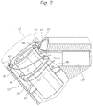
- the opening 36 of the connecting channel 26 lies in the coolant space 13 of the cylinder 7 in its lower and middle area, in particular in order to maintain a necessary distance from the return channel 30 arranged next to the upper area of the cylinder 7.
- a separating ring 37 is provided in the coolant space 13 approximately in the middle thereof, which is provided with a recess 44 in the region of the orifice opening 36 and is in particular made in one piece with the internal combustion engine housing and which Coolant space 13 separates into an upper annular space 38 and a lower annular space 39.
- the orifice opening 36 Although the major part of the orifice opening 36 is in the region of the lower annular space 39, a relatively small amount of cooling liquid flows into it only when in the Separating ring 37 is provided with a small recess 40 located on the side remote from the mouth opening 36. This allows the coolant to be drained from the upper annular space 39 and from the cylinder head 42 and reduces the turbulence in the lower annular space 39. In particular, however, the inflow of cooling liquid through the recess 40 into the lower area of the upper annular space 38, which is remote from the orifice 36, results in a dead water area being created in this area K.
- cooling liquid flows from the upper annular space 38 into a cooling space in the cylinder head 42 via an opening 45 which is on the side remote from the orifice opening 36.
- openings 41, 46 are provided, from which a smaller amount of cooling liquid flows into the cooling space of the cylinder head 42 and directly into the return duct 30.
- the return flow from the cooling chamber of the cylinder head 42 into the return duct 30 is denoted by 47.
Landscapes
- Engineering & Computer Science (AREA)
- Chemical & Material Sciences (AREA)
- Combustion & Propulsion (AREA)
- Mechanical Engineering (AREA)
- General Engineering & Computer Science (AREA)
- Cylinder Crankcases Of Internal Combustion Engines (AREA)
Applications Claiming Priority (2)
| Application Number | Priority Date | Filing Date | Title |
|---|---|---|---|
| DE4326161 | 1993-08-04 | ||
| DE4326161A DE4326161C2 (de) | 1993-08-04 | 1993-08-04 | Flüssigkeitsgekühlte Mehrzylinder-Brennkraftmaschine |
Publications (2)
| Publication Number | Publication Date |
|---|---|
| EP0637680A1 true EP0637680A1 (fr) | 1995-02-08 |
| EP0637680B1 EP0637680B1 (fr) | 1996-11-27 |
Family
ID=6494438
Family Applications (1)
| Application Number | Title | Priority Date | Filing Date |
|---|---|---|---|
| EP94110166A Expired - Lifetime EP0637680B1 (fr) | 1993-08-04 | 1994-06-30 | Moteur à combustion interne à plusieurs cylindres refroidi par liquide |
Country Status (2)
| Country | Link |
|---|---|
| EP (1) | EP0637680B1 (fr) |
| DE (2) | DE4326161C2 (fr) |
Cited By (1)
| Publication number | Priority date | Publication date | Assignee | Title |
|---|---|---|---|---|
| EP1122409A3 (fr) * | 2000-02-03 | 2003-02-12 | Honda Giken Kogyo Kabushiki Kaisha | Circuit de refroidissement de l'eau dans un moteur à combustion interne |
Families Citing this family (4)
| Publication number | Priority date | Publication date | Assignee | Title |
|---|---|---|---|---|
| DE19943002C2 (de) * | 1999-09-09 | 2003-01-23 | Porsche Ag | Kühleinrichtung für eine Brennkraftmaschine |
| DE19956358A1 (de) * | 1999-11-24 | 2001-05-31 | Bayerische Motoren Werke Ag | Flüssigkeitsgekühlte Brennkraftmaschine mit zueinander geneigt angeordneten Zylinderbänken, insbesondere V-Motor |
| AT5039U1 (de) * | 2000-12-21 | 2002-02-25 | Avl List Gmbh | Zylinderblock für eine flüssigkeitsgekühlte brennkraftmaschine |
| DE102013113609B4 (de) | 2013-12-06 | 2022-02-24 | Dr. Ing. H.C. F. Porsche Aktiengesellschaft | Kurbelgehäuse mit einer Kühlwasserverteilung für eine mehrzylindrige Brennkraftmaschine |
Citations (4)
| Publication number | Priority date | Publication date | Assignee | Title |
|---|---|---|---|---|
| DE3629673A1 (de) * | 1986-09-01 | 1988-03-10 | Kloeckner Humboldt Deutz Ag | Brennkraftmaschine mit fluessigkeitsgekuehlter zylinderlaufbuchse |
| US4945887A (en) * | 1988-09-30 | 1990-08-07 | Yamaha Hatsudoki Kabushiki Kaisha | Crankcase vent system |
| DE4001140C1 (en) * | 1990-01-17 | 1991-04-11 | Mercedes-Benz Aktiengesellschaft, 7000 Stuttgart, De | Cylinder block for liquid cooled IC engine - has coolant channels in internal angle of V=shaped block |
| DE4206920C1 (en) * | 1992-03-05 | 1992-12-24 | Mercedes-Benz Aktiengesellschaft, 7000 Stuttgart, De | Cooling circuit for vehicle IC engine - has connecting passage between opposing pairs of cylinders, and cooling fluid chamber |
Family Cites Families (2)
| Publication number | Priority date | Publication date | Assignee | Title |
|---|---|---|---|---|
| DE2727124A1 (de) * | 1977-06-16 | 1978-12-21 | Daimler Benz Ag | Einrichtung zur kuehlfluessigkeitsfuehrung im zylinderblock von mehrzylinder-brennkraftmaschinen |
| JPS58107840A (ja) * | 1981-12-22 | 1983-06-27 | Nissan Motor Co Ltd | V型内燃機関の冷却装置 |
-
1993
- 1993-08-04 DE DE4326161A patent/DE4326161C2/de not_active Expired - Lifetime
-
1994
- 1994-06-30 EP EP94110166A patent/EP0637680B1/fr not_active Expired - Lifetime
- 1994-06-30 DE DE59401127T patent/DE59401127D1/de not_active Expired - Lifetime
Patent Citations (4)
| Publication number | Priority date | Publication date | Assignee | Title |
|---|---|---|---|---|
| DE3629673A1 (de) * | 1986-09-01 | 1988-03-10 | Kloeckner Humboldt Deutz Ag | Brennkraftmaschine mit fluessigkeitsgekuehlter zylinderlaufbuchse |
| US4945887A (en) * | 1988-09-30 | 1990-08-07 | Yamaha Hatsudoki Kabushiki Kaisha | Crankcase vent system |
| DE4001140C1 (en) * | 1990-01-17 | 1991-04-11 | Mercedes-Benz Aktiengesellschaft, 7000 Stuttgart, De | Cylinder block for liquid cooled IC engine - has coolant channels in internal angle of V=shaped block |
| DE4206920C1 (en) * | 1992-03-05 | 1992-12-24 | Mercedes-Benz Aktiengesellschaft, 7000 Stuttgart, De | Cooling circuit for vehicle IC engine - has connecting passage between opposing pairs of cylinders, and cooling fluid chamber |
Cited By (1)
| Publication number | Priority date | Publication date | Assignee | Title |
|---|---|---|---|---|
| EP1122409A3 (fr) * | 2000-02-03 | 2003-02-12 | Honda Giken Kogyo Kabushiki Kaisha | Circuit de refroidissement de l'eau dans un moteur à combustion interne |
Also Published As
| Publication number | Publication date |
|---|---|
| DE4326161C2 (de) | 1995-06-14 |
| DE59401127D1 (de) | 1997-01-09 |
| EP0637680B1 (fr) | 1996-11-27 |
| DE4326161A1 (de) | 1995-02-09 |
Similar Documents
| Publication | Publication Date | Title |
|---|---|---|
| DE2417925C2 (de) | Flüssigkeitsgekühlte Mehrzylinder-Brennkraftmaschine | |
| DE112014005653B4 (de) | Flüssigkeitsgekühlte Brennkraftmaschine | |
| AT5301U1 (de) | Zylinderkopf für mehrere zylinder | |
| DE10344834B4 (de) | Motorkühlsystem | |
| EP2309106A1 (fr) | circuit de refroidissement | |
| DE102007062347B4 (de) | Kühlanordnung für einen Zylinderkopf einer Brennkraftmaschine | |
| WO2004001214A1 (fr) | Culasse refroidie pour moteur a combustion interne a pistons | |
| DE102018116973A1 (de) | Zylinderkopf und Kurbelgehäuse für eine Brennkraftmaschine | |
| EP0819837B1 (fr) | Circuit de refroidissement d'un moteur à combustion interne | |
| EP0637680B1 (fr) | Moteur à combustion interne à plusieurs cylindres refroidi par liquide | |
| DE4030200A1 (de) | Motorkuehlsystem | |
| DE60131487T2 (de) | Zylinderkopfkühlwasserstruktur und Verfahren zur Herstellung | |
| DE102009008237A1 (de) | Brennkraftmaschine mit getrennten Kühlmittelräumen im Zylinderkopf | |
| WO2001083958A1 (fr) | Circuit de refroidissement pour moteur a combustion interne multicylindre | |
| DE2544813A1 (de) | Brennkraftmaschine, insbesondere dieselmotor | |
| DE102014118060A1 (de) | Zylinderblock einer flüssigkeitsgekühlten Verbrennungskraftmaschine in Monoblock-Bauweise und Gießform zu dessen Herstellung | |
| DE10021526C2 (de) | Anordnung zur Kühlung einer mehrzylindrigen Brennkraftmaschine | |
| DE4001140C1 (en) | Cylinder block for liquid cooled IC engine - has coolant channels in internal angle of V=shaped block | |
| EP1103704B1 (fr) | Moteur à combustion refroidi par liquide avec les bancs-cylindres rangés en V | |
| EP0933510B1 (fr) | Moteur à combustion interne | |
| DE4206920C1 (en) | Cooling circuit for vehicle IC engine - has connecting passage between opposing pairs of cylinders, and cooling fluid chamber | |
| EP1329628B1 (fr) | Culasse pour un moteur à combustion à pistons avec un système de canaux de refroidissement | |
| DE102005057760B4 (de) | Kühlsystem für einen Motor | |
| DE4140772A1 (de) | Vorrichtung zur kuehlung der stege zwischen zylindern eines zylinderblocks einer brennkraftmaschine | |
| WO2005088111A1 (fr) | Culasse refroidie par eau pour un moteur a combustion interne |
Legal Events
| Date | Code | Title | Description |
|---|---|---|---|
| PUAI | Public reference made under article 153(3) epc to a published international application that has entered the european phase |
Free format text: ORIGINAL CODE: 0009012 |
|
| 17P | Request for examination filed |
Effective date: 19941210 |
|
| AK | Designated contracting states |
Kind code of ref document: A1 Designated state(s): DE FR GB IT SE |
|
| GRAG | Despatch of communication of intention to grant |
Free format text: ORIGINAL CODE: EPIDOS AGRA |
|
| 17Q | First examination report despatched |
Effective date: 19960208 |
|
| GRAH | Despatch of communication of intention to grant a patent |
Free format text: ORIGINAL CODE: EPIDOS IGRA |
|
| GRAH | Despatch of communication of intention to grant a patent |
Free format text: ORIGINAL CODE: EPIDOS IGRA |
|
| GRAA | (expected) grant |
Free format text: ORIGINAL CODE: 0009210 |
|
| ITF | It: translation for a ep patent filed | ||
| AK | Designated contracting states |
Kind code of ref document: B1 Designated state(s): DE FR GB IT SE |
|
| GBT | Gb: translation of ep patent filed (gb section 77(6)(a)/1977) |
Effective date: 19961211 |
|
| REF | Corresponds to: |
Ref document number: 59401127 Country of ref document: DE Date of ref document: 19970109 |
|
| ET | Fr: translation filed | ||
| RAP2 | Party data changed (patent owner data changed or rights of a patent transferred) |
Owner name: DAIMLER-BENZ AKTIENGESELLSCHAFT |
|
| PLBE | No opposition filed within time limit |
Free format text: ORIGINAL CODE: 0009261 |
|
| STAA | Information on the status of an ep patent application or granted ep patent |
Free format text: STATUS: NO OPPOSITION FILED WITHIN TIME LIMIT |
|
| 26N | No opposition filed | ||
| REG | Reference to a national code |
Ref country code: GB Ref legal event code: 732E |
|
| REG | Reference to a national code |
Ref country code: FR Ref legal event code: TP |
|
| REG | Reference to a national code |
Ref country code: GB Ref legal event code: 732E |
|
| REG | Reference to a national code |
Ref country code: GB Ref legal event code: IF02 |
|
| PGFP | Annual fee paid to national office [announced via postgrant information from national office to epo] |
Ref country code: GB Payment date: 20030530 Year of fee payment: 10 |
|
| PGFP | Annual fee paid to national office [announced via postgrant information from national office to epo] |
Ref country code: FR Payment date: 20030611 Year of fee payment: 10 |
|
| PG25 | Lapsed in a contracting state [announced via postgrant information from national office to epo] |
Ref country code: GB Free format text: LAPSE BECAUSE OF NON-PAYMENT OF DUE FEES Effective date: 20040630 |
|
| GBPC | Gb: european patent ceased through non-payment of renewal fee |
Effective date: 20040630 |
|
| PG25 | Lapsed in a contracting state [announced via postgrant information from national office to epo] |
Ref country code: FR Free format text: LAPSE BECAUSE OF NON-PAYMENT OF DUE FEES Effective date: 20050228 |
|
| REG | Reference to a national code |
Ref country code: FR Ref legal event code: ST |
|
| PGFP | Annual fee paid to national office [announced via postgrant information from national office to epo] |
Ref country code: IT Payment date: 20120621 Year of fee payment: 19 |
|
| PGFP | Annual fee paid to national office [announced via postgrant information from national office to epo] |
Ref country code: SE Payment date: 20120629 Year of fee payment: 19 |
|
| PGFP | Annual fee paid to national office [announced via postgrant information from national office to epo] |
Ref country code: DE Payment date: 20120830 Year of fee payment: 19 |
|
| REG | Reference to a national code |
Ref country code: DE Ref legal event code: R081 Ref document number: 59401127 Country of ref document: DE Owner name: WERNER, JOHANN, DE Free format text: FORMER OWNER: DAIMLER AG, 70327 STUTTGART, DE Effective date: 20131126 |
|
| REG | Reference to a national code |
Ref country code: SE Ref legal event code: EUG |
|
| REG | Reference to a national code |
Ref country code: DE Ref legal event code: R119 Ref document number: 59401127 Country of ref document: DE Effective date: 20140101 |
|
| PG25 | Lapsed in a contracting state [announced via postgrant information from national office to epo] |
Ref country code: SE Free format text: LAPSE BECAUSE OF NON-PAYMENT OF DUE FEES Effective date: 20130701 Ref country code: DE Free format text: LAPSE BECAUSE OF NON-PAYMENT OF DUE FEES Effective date: 20140101 |
|
| PG25 | Lapsed in a contracting state [announced via postgrant information from national office to epo] |
Ref country code: IT Free format text: LAPSE BECAUSE OF NON-PAYMENT OF DUE FEES Effective date: 20130630 |