EP0637700A2 - Spiralfeder aus kohlenfaserverstärktem Kunststoff und Verfahren zur Herstellung - Google Patents
Spiralfeder aus kohlenfaserverstärktem Kunststoff und Verfahren zur Herstellung Download PDFInfo
- Publication number
- EP0637700A2 EP0637700A2 EP94305779A EP94305779A EP0637700A2 EP 0637700 A2 EP0637700 A2 EP 0637700A2 EP 94305779 A EP94305779 A EP 94305779A EP 94305779 A EP94305779 A EP 94305779A EP 0637700 A2 EP0637700 A2 EP 0637700A2
- Authority
- EP
- European Patent Office
- Prior art keywords
- coil spring
- fibers
- cord
- prepregs
- carbon fibers
- Prior art date
- Legal status (The legal status is an assumption and is not a legal conclusion. Google has not performed a legal analysis and makes no representation as to the accuracy of the status listed.)
- Granted
Links
Images


Classifications
-
- B—PERFORMING OPERATIONS; TRANSPORTING
- B29—WORKING OF PLASTICS; WORKING OF SUBSTANCES IN A PLASTIC STATE IN GENERAL
- B29C—SHAPING OR JOINING OF PLASTICS; SHAPING OF MATERIAL IN A PLASTIC STATE, NOT OTHERWISE PROVIDED FOR; AFTER-TREATMENT OF THE SHAPED PRODUCTS, e.g. REPAIRING
- B29C53/00—Shaping by bending, folding, twisting, straightening or flattening; Apparatus therefor
- B29C53/02—Bending or folding
- B29C53/08—Bending or folding of tubes or other profiled members
- B29C53/083—Bending or folding of tubes or other profiled members bending longitudinally, i.e. modifying the curvature of the tube axis
-
- B—PERFORMING OPERATIONS; TRANSPORTING
- B29—WORKING OF PLASTICS; WORKING OF SUBSTANCES IN A PLASTIC STATE IN GENERAL
- B29C—SHAPING OR JOINING OF PLASTICS; SHAPING OF MATERIAL IN A PLASTIC STATE, NOT OTHERWISE PROVIDED FOR; AFTER-TREATMENT OF THE SHAPED PRODUCTS, e.g. REPAIRING
- B29C53/00—Shaping by bending, folding, twisting, straightening or flattening; Apparatus therefor
- B29C53/02—Bending or folding
- B29C53/12—Bending or folding helically, e.g. for making springs
-
- B—PERFORMING OPERATIONS; TRANSPORTING
- B29—WORKING OF PLASTICS; WORKING OF SUBSTANCES IN A PLASTIC STATE IN GENERAL
- B29C—SHAPING OR JOINING OF PLASTICS; SHAPING OF MATERIAL IN A PLASTIC STATE, NOT OTHERWISE PROVIDED FOR; AFTER-TREATMENT OF THE SHAPED PRODUCTS, e.g. REPAIRING
- B29C70/00—Shaping composites, i.e. plastics material comprising reinforcements, fillers or preformed parts, e.g. inserts
- B29C70/04—Shaping composites, i.e. plastics material comprising reinforcements, fillers or preformed parts, e.g. inserts comprising reinforcements only, e.g. self-reinforcing plastics
- B29C70/06—Fibrous reinforcements only
- B29C70/10—Fibrous reinforcements only characterised by the structure of fibrous reinforcements, e.g. hollow fibres
- B29C70/16—Fibrous reinforcements only characterised by the structure of fibrous reinforcements, e.g. hollow fibres using fibres of substantial or continuous length
- B29C70/20—Fibrous reinforcements only characterised by the structure of fibrous reinforcements, e.g. hollow fibres using fibres of substantial or continuous length oriented in a single direction, e.g. roofing or other parallel fibres
- B29C70/205—Fibrous reinforcements only characterised by the structure of fibrous reinforcements, e.g. hollow fibres using fibres of substantial or continuous length oriented in a single direction, e.g. roofing or other parallel fibres the structure being shaped to form a three-dimensional configuration
- B29C70/207—Fibrous reinforcements only characterised by the structure of fibrous reinforcements, e.g. hollow fibres using fibres of substantial or continuous length oriented in a single direction, e.g. roofing or other parallel fibres the structure being shaped to form a three-dimensional configuration arranged in parallel planes of fibres crossing at substantial angles
-
- B—PERFORMING OPERATIONS; TRANSPORTING
- B29—WORKING OF PLASTICS; WORKING OF SUBSTANCES IN A PLASTIC STATE IN GENERAL
- B29C—SHAPING OR JOINING OF PLASTICS; SHAPING OF MATERIAL IN A PLASTIC STATE, NOT OTHERWISE PROVIDED FOR; AFTER-TREATMENT OF THE SHAPED PRODUCTS, e.g. REPAIRING
- B29C70/00—Shaping composites, i.e. plastics material comprising reinforcements, fillers or preformed parts, e.g. inserts
- B29C70/04—Shaping composites, i.e. plastics material comprising reinforcements, fillers or preformed parts, e.g. inserts comprising reinforcements only, e.g. self-reinforcing plastics
- B29C70/28—Shaping operations therefor
- B29C70/30—Shaping by lay-up, i.e. applying fibres, tape or broadsheet on a mould, former or core; Shaping by spray-up, i.e. spraying of fibres on a mould, former or core
-
- F—MECHANICAL ENGINEERING; LIGHTING; HEATING; WEAPONS; BLASTING
- F16—ENGINEERING ELEMENTS AND UNITS; GENERAL MEASURES FOR PRODUCING AND MAINTAINING EFFECTIVE FUNCTIONING OF MACHINES OR INSTALLATIONS; THERMAL INSULATION IN GENERAL
- F16F—SPRINGS; SHOCK-ABSORBERS; MEANS FOR DAMPING VIBRATION
- F16F1/00—Springs
- F16F1/02—Springs made of steel or other material having low internal friction; Wound, torsion, leaf, cup, ring or the like springs, the material of the spring not being relevant
- F16F1/021—Springs made of steel or other material having low internal friction; Wound, torsion, leaf, cup, ring or the like springs, the material of the spring not being relevant characterised by their composition, e.g. comprising materials providing for particular spring properties
-
- F—MECHANICAL ENGINEERING; LIGHTING; HEATING; WEAPONS; BLASTING
- F16—ENGINEERING ELEMENTS AND UNITS; GENERAL MEASURES FOR PRODUCING AND MAINTAINING EFFECTIVE FUNCTIONING OF MACHINES OR INSTALLATIONS; THERMAL INSULATION IN GENERAL
- F16F—SPRINGS; SHOCK-ABSORBERS; MEANS FOR DAMPING VIBRATION
- F16F1/00—Springs
- F16F1/36—Springs made of rubber or other material having high internal friction, e.g. thermoplastic elastomers
- F16F1/366—Springs made of rubber or other material having high internal friction, e.g. thermoplastic elastomers made of fibre-reinforced plastics, i.e. characterised by their special construction from such materials
- F16F1/3665—Wound springs
-
- B—PERFORMING OPERATIONS; TRANSPORTING
- B29—WORKING OF PLASTICS; WORKING OF SUBSTANCES IN A PLASTIC STATE IN GENERAL
- B29K—INDEXING SCHEME ASSOCIATED WITH SUBCLASSES B29B, B29C OR B29D, RELATING TO MOULDING MATERIALS OR TO MATERIALS FOR MOULDS, REINFORCEMENTS, FILLERS OR PREFORMED PARTS, e.g. INSERTS
- B29K2105/00—Condition, form or state of moulded material or of the material to be shaped
- B29K2105/06—Condition, form or state of moulded material or of the material to be shaped containing reinforcements, fillers or inserts
-
- B—PERFORMING OPERATIONS; TRANSPORTING
- B29—WORKING OF PLASTICS; WORKING OF SUBSTANCES IN A PLASTIC STATE IN GENERAL
- B29K—INDEXING SCHEME ASSOCIATED WITH SUBCLASSES B29B, B29C OR B29D, RELATING TO MOULDING MATERIALS OR TO MATERIALS FOR MOULDS, REINFORCEMENTS, FILLERS OR PREFORMED PARTS, e.g. INSERTS
- B29K2707/00—Use of elements other than metals for preformed parts, e.g. for inserts
- B29K2707/04—Carbon
-
- B—PERFORMING OPERATIONS; TRANSPORTING
- B29—WORKING OF PLASTICS; WORKING OF SUBSTANCES IN A PLASTIC STATE IN GENERAL
- B29L—INDEXING SCHEME ASSOCIATED WITH SUBCLASS B29C, RELATING TO PARTICULAR ARTICLES
- B29L2031/00—Other particular articles
- B29L2031/774—Springs
- B29L2031/7742—Springs helical springs
Definitions
- This invention relates to a carbon fiber reinforced resin coil spring and method for manufacturing the same, and more specifically to a coil spring consisting of a spirally wound cord made of carbon fiber reinforced resin and its manufacturing method.
- U.S. Patent No.2852424 proposes a fiber reinforced resin coil spring which is more lightweight than a conventional metal coil spring.
- the coil spring is made of resin impregnated glass roving which is wound on a mandrel for forming a coiled structure.
- the orientation of the reinforced fibers is uniform and is parallel to the axis of the cord.
- Japanese Patent Laid Open No.56-18136 discloses a coil spring in which the orientation of the fibers is chosen relative to the axis of the cord. Namely, all the reinforcing fibers are oriented with respect to the direction in which the fibers are subject to a tensile force when a load is applied to the coil spring.
- the orientation angle is within the range of 30 ° ⁇ 60° relative to the axis of the cord.
- Japanese Patent Laid Open No.57-11742 discloses a coil spring in which the reinforcing fibers are inclined at a predetermined oblique angle with respect to the axis of the cord. Further, the reinforcing fibers are wound in the two different directions so that the two groups of fibers cross over each other, the cross-over angle at the center in the longitudinal direction being different from the angles at both ends.
- Such an arrangement of reinforced fibers allows regulation of torsional rigidity and gives the coil spring a non-linear spring constant.
- carbon fiber is a material having excellent mechanical properties; hence carbon fiber reinforced resins have excellent features.
- the carbon fiber reinforced resin also has the disadvantage of relatively low compressive strength compared with tensile strength.
- the cord When weight or force is applied to the coil spring having oblique reinforcing fibers with respect to the axis of the cord which are wound in two different directions and which cross each other, the cord receives a torsional stress.
- This torsional stress causes a compressive force to act on the first group of oriented fibers and a tensile force to act on the second group of oriented fibers. Due to this characteristic of the carbon fiber reinforced resin composites, the fracture of the coil spring begins in the layer in which the reinforcing fibers are oriented in the direction of compression.
- substantially all the reinforcing fibers are oriented in the same direction. In this kind of coil spring, the strength of the spring in the direction at 90 ° relative to the direction of the oriented fibers is low, so the spring is easily destroyed.
- the coil spring shown in Japanese Patent Laid Open No.57-11742 has two groups of reinforcing fibers, having different orientations which cross over each other. With this arrangement, the problem of the spring's weakness in the direction at 90° relative to the orientation of the fibers is solved. However, the defect whereby the carbon fiber reinforced resin has a low compressive strength is left unsolved.
- This invention is based on the knowledge that the fracture of the coil spring made of carbon fiber reinforced resin begins in the fibers oriented in the same direction as that of the applied compression, and on the theory that the overall strength of the coil spring increases when the fracture of the fibers in the direction of the compression is controlled.
- Another object of this invention is to provide a carbon fiber reinforced resin coil spring wherein the ratio A/B, of the amount of fibers oriented in the direction the compressive force is applied and the amount of fibers oriented in the direction the tensile force is applied, is adjusted to be within a desirable range.
- a further object of this invention is to provide a method for manufacturing a carbon fiber reinforced resin coil spring having a desirable balance between compressive strength and tensile strength.
- a still further object of this invention is to provide a method for manufacturing a carbon fiber reinforced resin coil spring in which the ratio A/B,of the amount of fibers oriented in the direction the compressive force is applied and the amount of fibers oriented in the direction the tensile force is applied, is adjusted to be within a predetermined range.
- a carbon fiber reinforced resin coil spring consisting of a spirally wound cord which is made from carbon fiber reinforced resin; characterized in that the carbon fibers are orientated at an angle of ⁇ 30 ⁇ 60° relative to the axis of the cord; and the ratio of the amounts of the carbon fibers A and B lies within the range 1.1 ⁇ A/B ⁇ 4.0 where A is the amount of carbon fibers oriented in the direction the compressive force is applied and B is the amount of carbon fibers oriented in the direction the tensile force is applied.
- a carbon fiber fabric is arranged as the outermost layer of the cord.
- the compressive force is caused by the carbon fibers oriented in the compression direction , which prevents the fracture of the spring in the direction the compressive force is applied. Hence, a coil spring having high shearing strength is obtained.
- the orientation of the fibers is defined by the angle between the axis of the cord and the fiber axis.
- the direction wherein the tensile force is applied in the cord is assumed to be the plus (+) direction
- the direction wherein the compressive force is applied is assumed to be the minus (-) direction.
- the carbon fibers utilized as the reinforcing material may be any ordinary carbon fibers such as polyacrylnitril (PAN) based carbon fibers, pitch based carbon fibers, and rayon based carbon fibers. From the viewpoint of compressive strength, PAN based carbon fibers are to be preferred. High strength PAN based carbon fibers are especially preferred because of their high compressive strength.
- PAN polyacrylnitril
- This invention does not prohibit the use of other fibers in conjunction with the carbon fiber, for example, glass fiber, aramid fiber or highly extensible fiber, in the shape of a filament, unwoven fabric, or woven fabric in accordance with the purpose to which the coil spring may be put.
- the matrix resin reinforced by the carbon fiber may be a thermosetting resin or a thermoplastic resin.
- thermosetting resins are epoxy resin, polyimide resin, and unsaturated polyester resin
- thermoplastic resins are polysulfonic resin, polyethersulfonic resin, polycarbonate resin, polyetherketone resin, polyetheretherketone resin, aromatic polyamide resin, polyetherimide resin, and thermoplastic polyimide resin.
- a suitable combination of the reinforcing fiber and the matrix resin is selected from the above-mentioned materials.
- the fiber and the resin arranged in the plus direction may both be the same as or different from the fiber and the resin arranged in the minus direction.
- the orientation of the fibers may be adjusted within the range of ⁇ 30° ⁇ 60° in accordance with the required characteristics of the coil spring. The angle should be selected to be in the vicinity of ⁇ 45° when high shearing strength is required.
- a prepreg may be used in the form of a sheet, tape or strand of reinforcing fiber previously impregnated with uncured thermosetting resin.
- the so-called filament winding method may also be utilized wherein a filament is wound on a mandrel while it is impregnated with the resin.
- Fig.1 and Fig.2 show carbon fiber reinforced resin coil springs which are respectively subject to a compressive force and a tensile force.
- Fig.3 and Fig.4 show enlarged partial fragments of the strand whereof coil spring 10 shown in Fig.1 and Fig.2 are formed.
- the compressive stress acts on the fibers oriented in the direction denoted by A
- the tensile stress acts on the fibers oriented in the direction denoted by B, when the coil spring is subject to a compressive force as shown by Fig.1 and Fig.3.
- the compressive stress acts on the fibers oriented in the direction denoted by A
- the tensile stress acts on the fibers oriented in the direction denoted by B, when the coil spring is subject to a tensile force as shown by Fig.2 and Fig.4.
- a more preferred range for the ratio A/B between the amount A of the fibers subject to a compressive force and the amount B of the fibers subject to a tensile force is 1.2 ⁇ A/B ⁇ 3.0, and a still more preferred range for the ratio A/B is: 1.3 ⁇ A/B ⁇ 2.5.
- the ratio of the amounts A/B is less than 1.1 or 1.1 ⁇ A/B, the strength of the spring in the direction the compressive force applies becomes low, and the equilibrium in the direction the tensile force applies will be upset, hence a high strength coil spring cannot be obtained.
- the ratio of the amounts A/B is more than 4.0 or A/B ⁇ 4.0, the strength of the spring in the direction the tensile force applies becomes low, and the equilibrium in the direction the compressive force applies will be upset, hence in this case also a high strength coil spring cannot be obtained.
- the adjustment of the ratio A/B of the amounts of fibers in two different directions is performed when the fibers are overlaid.
- a prepreg in the plus direction and a prepreg in minus direction are used, and the weight of fibers in the former is varied from that in the latter to perform the adjustment.
- two kinds of prepregs 15, 16, each containing an equal weight of fibers are used, and the number of the prepregs 15 in the plus direction is varied from the number of the prepregs 16 in the minus direction to perform the adjustment.
- the above-mentioned two methods may be combined for the adjustment of the amount ratio A/B.
- the fibers are first wound on the mandrel in the positive direction, and then the mandrel is driven in the opposite direction for winding the fibers in the negative direction.
- the amounts of the fibers in the two directions are regulated so that the ratio of the amounts of fibers in these directions lies within the predetermined range.
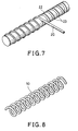
- a preferred process according to this invention for manufacturing the fiber reinforced resin coil spring is as follows. As shown in Fig.5, two kinds of prepregs 15, 16 made of reinforcing carbon fibers and a thermosetting resin, and each containing equal weights of fibers, are prepared. The number of sheets of the above-mentioned two kinds of prepregs 15, 16 is regulated, and the prepregs 15, 16 are wound on a flexible mandrel 18 as shown in Fig.6 . By this process, a cylindrical cord 20 is obtained. The cord 20 is then wound on a spiral groove 23 formed on the peripheral surface of a columnar die 22 as shown in Fig. 7, the cord 20 is fixed, and the resin is cured by heat. The cord is then removed from the die so as to obtain the coil spring 10 as shown in Fig. 8.
- a flexible mandrel is used as shown in Fig. 6.
- Suitable materials for the mandrel are Nylon, silicone resin, Teflon and polymethylpentene. From the viewpoint of handling properties and thermal stability, polymethylpentene is preferred. As these materials are lighter than metals, it is not necessary to form a hollow to decrease weight, and it is therefore possible to use a cord 20 wherein the mandrel 18 has been left inside.
- a coil spring made of such solid cords has high buckling strength.
- the outermost layer of the material may be made of fabric prepreg.
- Fig.1 is a partial front view of a coil spring subject to a compressive force.
- Fig.2 is a partial front view of a coil spring subject to a tensile force.
- Fig.3 is a partially enlarged perspective view of a cord of the coil spring subject to a compressive force.
- Fig.4 is a partially enlarged perspective view of a cord of the coil spring subject to a tensile force.
- Fig.5 is an exploded perspective view of a prepreg for the cord.
- Fig.6 is an enlarged cross section of a cord made from a prepreg wound on a mandrel.
- Fig.7 is a perspective view of a die on the spiral groove of which the cord is wound.
- Fig.8 is a perspective view of a manufactured coil spring.
- Carbon fiber/ epoxy resin prepregs (manufactured by Toho Rayon Co. Ltd.) in which all the carbon fibers are uniformly orientated in one direction were prepared.
- a prepreg sheet was then obtained by laminating the prepregs so that the carbon fibers of the first group of prepregs and those of the second group of prepregs crossed each other at an angle of ⁇ 45° , and the amount ratio A/B of the plus direction fibers and the minus direction fibers was 1.39.
- the above-mentioned prepreg sheet was wound on the mandrel in such a manner that the side edge of the sheet was parallel to the axis of the mandrel and the directions of the fibers of the prepregs were ⁇ 45° . A cord of diameter 17 mm was thereby obtained.
- the cord was wrapped by polyester tape and fixed on the spiral groove of the die.
- the cord was then heated, first for 30 minutes at a temperature of 80 ° C and then for 2 hours at a temperature of 130 ° C.
- the resin of the cord was thereby compressed by the shrinkage of the tape, and the resin was cured.
- the cured resin coil spring was then taken out of the groove of the die.
- a jig was fitted on the top of the coil spring for the purpose of carrying out a compressive test using an Instron type testing machine.
- a load was applied to the center axis of the coil spring.
- the result of the test shows that the corrected shearing strength was 57 kgf/mm 2 .
- the amount ratio A/B of the fibers in the plus and minus direction was changed to 1.67 as shown in Table 1.
- the other conditions were the same as those of the first example.
- a coil spring was manufactured for the compressive test in the same manner as that of Example 1. According to the test results, the corrected shearing strength of the coil spring of this example was found to be 52 kgf/mm2 .
- the amount ratio A/B of the fibers in the plus and minus directions was changed to 2.0.
- the other conditions were the same as those of the first example.
- a coil spring was manufactured for the compressive test in the same manner as that of Example 1.
- the resulting corrected shearing strength was 45 kgf/mm 2 .
- the amount ratio A/B of the fibers in the plus and minus directions was set at 0.5.
- the other conditions were the same as those of Example 1.
- a coil spring was manufactured for the compressive test which was performed in the same manner as that of Example 1. According to the results of the compressive test, the corrected shearing strength was 38 kgf/mm2 . This value is rather low in comparison to the values of Examples 1 ⁇ 3.
- the amount ratio A/B of the fibers in the plus and minus directions was set at 1.0.
- the other conditions were the same as those of Example 1.
- a coil spring was manufactured and tested for compression in the same manner as that of the first example.
- the corrected shearing strength was 39 kgf/mm2 as shown in Table 1. This value is substantially the same as that of comparative Example 1.
- a bundle of high strength carbon fibers (Besfight, manufactured by Toho Rayon Co. Ltd.) was impregnated with bisphenol-A type epoxy resin containing hardener.
- the resin-impregnated bundle of carbon fibers was wound on a mandrel by the filament winding method in such a manner that the amount ratio A/B of the fibers in the plus and minus directions was 1.67, and the directions of the two groups of fibers was ⁇ 45° relative to the axis of the mandrel.
- a cord was thereby manufactured. This cord was molded by the same process as that used in the first example.
- the coil spring so manufactured was then subjected to a compressive test as in the first example. The result of the test showed that the corrected shearing strength of the spring was 53 kgf/mm2 .
- a carbon fiber/ epoxy resin prepreg (manufactured by Toho Rayon Co. Ltd.) in which all the carbon fibers were uniformly oriented in one direction was used.
- a plurality of prepregs were laminated on each other in such a manner that the amount ratio A/B of the fibers in the plus and minus directions was 1.39, and the directions of the two groups of fibers was ⁇ 45° .
- the laminated sheet was wound on a mandrel in such a manner that the side edge of the sheet was parallel to the axis of the mandrel, and the directions of the reinforcing fibers were ⁇ 45° relative to the axis of the resulting cords.
- Another plain woven prepreg manufactured by Toho Rayon Co. Ltd. was wound on the outer surface so that the angles of the fibers were ⁇ 45° . In this way, a cord was obtained which was molded by the same process as that of the first example, resulting in a coil spring wherein the amount ratio A/B was 1.33.
- This coil spring had a smooth surface and novel design because of its outermost prepreg of fabric.
- the shearing strength of the coil spring was 56 kgf/mm2 , which is a relatively high value.
- a coil spring wherein the amount ratio A/B was 1.39 and whereof the shape and dimensions were the same as those of the coil spring of the first example, was manufactured.
- the coil spring was then subjected to a tensile test wherein a tensile force was applied to the coil spring.
- the corrected shearing strength was 43 kgf/mm2 .
- the amount ratio A/B was set at 1.0, the other conditions being the same as those of the first example.
- a tension coil spring was thereby manufactured. This coil spring was subjected to a tensile test. The result of the test showed that the corrected shearing strength was 31 kgf/mm2 .
Landscapes
- Engineering & Computer Science (AREA)
- Mechanical Engineering (AREA)
- General Engineering & Computer Science (AREA)
- Chemical & Material Sciences (AREA)
- Composite Materials (AREA)
- Textile Engineering (AREA)
- Springs (AREA)
- Moulding By Coating Moulds (AREA)
Applications Claiming Priority (2)
| Application Number | Priority Date | Filing Date | Title |
|---|---|---|---|
| JP5212368A JP3009311B2 (ja) | 1993-08-04 | 1993-08-04 | 繊維強化樹脂製コイルスプリングおよびその製造方法 |
| JP212368/93 | 1993-08-04 |
Publications (3)
| Publication Number | Publication Date |
|---|---|
| EP0637700A2 true EP0637700A2 (de) | 1995-02-08 |
| EP0637700A3 EP0637700A3 (de) | 1995-05-03 |
| EP0637700B1 EP0637700B1 (de) | 1999-05-12 |
Family
ID=16621407
Family Applications (1)
| Application Number | Title | Priority Date | Filing Date |
|---|---|---|---|
| EP94305779A Expired - Lifetime EP0637700B1 (de) | 1993-08-04 | 1994-08-04 | Spiralfeder aus kohlenfaserverstärktem Kunststoff und Verfahren zur Herstellung |
Country Status (4)
| Country | Link |
|---|---|
| US (1) | US5685525A (de) |
| EP (1) | EP0637700B1 (de) |
| JP (1) | JP3009311B2 (de) |
| DE (1) | DE69418394T2 (de) |
Cited By (9)
| Publication number | Priority date | Publication date | Assignee | Title |
|---|---|---|---|---|
| EP0812673A3 (de) * | 1996-06-13 | 1999-05-12 | Fuji Jukogyo Kabushiki Kaisha | Zylindrischer Gegenstand aus faserverstärktem Verbundwerkstoff und Verfahren zu dessen Herstellung |
| EP1298347A3 (de) * | 2001-09-26 | 2004-07-21 | ArvinMeritor Technology, LLC | Drehstabfeder |
| WO2014014481A1 (en) * | 2012-07-18 | 2014-01-23 | Mssc Us | Composite coil spring |
| DE102014207151A1 (de) | 2014-04-14 | 2015-10-15 | Leichtbau-Zentrum Sachsen Gmbh | Torsionsbelastetes stabförmiges Bauteil |
| WO2015188963A1 (de) | 2014-06-11 | 2015-12-17 | Thyssenkrupp Ag | Torsionsbelastetes stabförmiges bauteil mit unterschiedlichen faserverstärkungen für zug- und druckbelastung |
| WO2018130561A1 (de) | 2017-01-10 | 2018-07-19 | Basf Se | Strangprofil und verfahren zum herstellen eines strangprofils |
| WO2018199365A1 (ko) * | 2017-04-28 | 2018-11-01 | 윈엔윈(주) | 카본섬유 강화 복합소재 스프링 제조방법 및 이의 제조방법에 의해 제조된 카본섬유 강화 복합소재 스프링 |
| WO2019036801A1 (en) | 2017-08-24 | 2019-02-28 | Ressorts Liberte Inc. | HELICAL SPRING AND METHOD FOR MANUFACTURING THE SAME |
| WO2019219694A1 (de) | 2018-05-14 | 2019-11-21 | Basf Polyurethanes Gmbh | Verfahren zur herstellung einer composite-feder, und selbige |
Families Citing this family (34)
| Publication number | Priority date | Publication date | Assignee | Title |
|---|---|---|---|---|
| US5988612A (en) * | 1997-08-07 | 1999-11-23 | Bertelson; Peter C. | Composite helical springs and process of manufacture |
| US6454251B1 (en) * | 2000-05-01 | 2002-09-24 | John C. Fish | Composite cord assembly |
| JP2002371461A (ja) * | 2001-06-13 | 2002-12-26 | Tokai Univ | 超高強度炭素繊維及び高強度炭素繊維強化炭素複合体 |
| DE10228406B4 (de) * | 2001-06-25 | 2016-09-15 | Bernhard Scheuring | Verwendung eines Verbundbauteils sowie Verfahren zur Herstellung des verwendeten Verbundbauteils |
| US7591592B2 (en) * | 2002-08-12 | 2009-09-22 | Menza Limited | Journal |
| DE102004039504B4 (de) * | 2003-09-09 | 2017-05-11 | Man Truck & Bus Ag | Mehrteilige Ventilfeder eines Kraftfahrzeugmotors |
| US20080017689A1 (en) * | 2006-05-31 | 2008-01-24 | David Simonelli | Fastener driving device |
| US8505798B2 (en) | 2005-05-12 | 2013-08-13 | Stanley Fastening Systems, L.P. | Fastener driving device |
| WO2006124498A2 (en) * | 2005-05-12 | 2006-11-23 | Stanley Fastening Systems, L.P. | Fastener driving device |
| US20140148917A1 (en) * | 2012-11-27 | 2014-05-29 | Ronald Harry Nelson | Carbon fiber prosthetic foot with hollow cross sections |
| US20100116864A1 (en) * | 2008-11-07 | 2010-05-13 | Pneutools, Incorporated | Motorized fastener applicator |
| DE102011018217A1 (de) | 2010-04-19 | 2011-12-15 | Leichtbau-Zentrum Sachsen Gmbh | Verfahren zur Herstellung von Federelementen aus Faserverbundwerkstoffen |
| JP5735826B2 (ja) | 2011-03-10 | 2015-06-17 | 日本発條株式会社 | 繊維強化プラスチック製ばね |
| CN202441794U (zh) * | 2012-03-02 | 2012-09-19 | 喜临门家具股份有限公司 | 一种螺旋状气压弹簧 |
| JP5921295B2 (ja) * | 2012-04-04 | 2016-05-24 | 株式会社シマノ | ブランク及び釣竿 |
| DE102012112939A1 (de) * | 2012-12-21 | 2014-06-26 | Leichtbau-Zentrum Sachsen Gmbh | Vorrichtung und Verfahren zur Infiltration einer Faserpreform |
| US10240654B2 (en) * | 2013-04-03 | 2019-03-26 | Mubea Carbo Tech Gmbh | Hybrid spring device |
| US20150047224A1 (en) * | 2013-08-16 | 2015-02-19 | Jing Zhao | Shoe having carbon fiber composite spring soles and upper support |
| JP6358645B2 (ja) * | 2013-10-31 | 2018-07-18 | 東洋炭素株式会社 | コイルバネ |
| CA2833674A1 (en) * | 2013-11-15 | 2015-05-15 | Rem Enterprises Inc. | Method for coating an extension spring |
| JP5864647B2 (ja) * | 2014-03-14 | 2016-02-17 | ミズノ テクニクス株式会社 | 繊維強化樹脂製コイルバネ、及び繊維強化樹脂製コイルバネの製造方法 |
| US9889633B2 (en) | 2014-04-10 | 2018-02-13 | Honda Motor Co., Ltd. | Attachment method for laminate structures |
| DE102014115619A1 (de) * | 2014-10-28 | 2016-04-28 | Dr. Ing. H.C. F. Porsche Aktiengesellschaft | Spiralfeder und zugehöriges Herstellungsverfahren |
| JP6502235B2 (ja) | 2015-10-29 | 2019-04-17 | 日本発條株式会社 | 弾性部材用線材および弾性部材 |
| JP2017082967A (ja) * | 2015-10-29 | 2017-05-18 | 日本発條株式会社 | コイルばね用線材およびコイルばね |
| JP2017081048A (ja) * | 2015-10-29 | 2017-05-18 | 日本発條株式会社 | 弾性部材用線材および弾性部材 |
| JP6832338B2 (ja) | 2016-03-23 | 2021-02-24 | 日本発條株式会社 | コイルばね |
| JP6910211B2 (ja) * | 2017-06-07 | 2021-07-28 | 株式会社Cfcデザイン | 炭素/炭素複合材製スプリング素子およびその製法 |
| CN107285796B (zh) * | 2017-07-21 | 2020-09-04 | 湖南金博碳素股份有限公司 | 碳基复合材料螺旋弹簧及生产方法 |
| DE102017218553B4 (de) * | 2017-10-18 | 2019-07-11 | Ford Global Technologies, Llc | Herstellungsverfahren für Blattfedern aus faserverstärktem Kunststoff mit integrierten Augenbuchsen und Blattfeder aus faserverstärktem Kunststoff |
| US11617670B2 (en) | 2018-01-10 | 2023-04-04 | Grd Innovations, Llc | Variable radius spring assembly |
| MX2021011700A (es) * | 2019-07-01 | 2021-10-13 | Mitsubishi Steel Mfg | Muelle en espiral compuesto con capas de fibra de carbono y de vidrio. |
| CN110512155B (zh) * | 2019-07-11 | 2020-06-26 | 江苏长龄液压股份有限公司 | 一种变截面弹簧坯料以及加工工装和加工工艺 |
| TWI883913B (zh) * | 2024-04-12 | 2025-05-11 | 邱長塤 | 複合材料螺旋彈簧結構 |
Family Cites Families (9)
| Publication number | Priority date | Publication date | Assignee | Title |
|---|---|---|---|---|
| US4260143A (en) * | 1979-01-15 | 1981-04-07 | Celanese Corporation | Carbon fiber reinforced composite coil spring |
| US4380483A (en) * | 1979-01-15 | 1983-04-19 | Celanese Corporation | Process for forming improved carbon fiber reinforced composite coil spring |
| CA1154042A (en) * | 1979-07-12 | 1983-09-20 | Frank H. Doyal | Fiber-reinforced tubular spring |
| GB8316690D0 (en) * | 1983-06-20 | 1983-07-20 | Secretary Industry Brit | Springs of fibre-reinforced plastics material |
| JPS6044627A (ja) * | 1983-08-22 | 1985-03-09 | Mitsubishi Rayon Co Ltd | コイルばね |
| MC1620A1 (fr) * | 1984-05-17 | 1985-07-18 | Silvatrim | Procede pour la fabrication de ressorts helicoidaux |
| DE3506037C1 (de) * | 1985-02-21 | 1986-01-16 | Deutsche Forschungs- und Versuchsanstalt für Luft- und Raumfahrt e.V., 5300 Bonn | Schraubenfeder sowie Verfahren zu deren Herstellung |
| JPS62215135A (ja) * | 1986-03-12 | 1987-09-21 | Somar Corp | 繊維強化プラスチツク製棒状捩りばね |
| JPH01269736A (ja) * | 1988-04-22 | 1989-10-27 | Mitsubishi Heavy Ind Ltd | つる巻きばね |
-
1993
- 1993-08-04 JP JP5212368A patent/JP3009311B2/ja not_active Expired - Fee Related
-
1994
- 1994-08-02 US US08/284,136 patent/US5685525A/en not_active Expired - Lifetime
- 1994-08-04 DE DE69418394T patent/DE69418394T2/de not_active Expired - Lifetime
- 1994-08-04 EP EP94305779A patent/EP0637700B1/de not_active Expired - Lifetime
Cited By (27)
| Publication number | Priority date | Publication date | Assignee | Title |
|---|---|---|---|---|
| EP0812673A3 (de) * | 1996-06-13 | 1999-05-12 | Fuji Jukogyo Kabushiki Kaisha | Zylindrischer Gegenstand aus faserverstärktem Verbundwerkstoff und Verfahren zu dessen Herstellung |
| EP1298347A3 (de) * | 2001-09-26 | 2004-07-21 | ArvinMeritor Technology, LLC | Drehstabfeder |
| CN104583637A (zh) * | 2012-07-18 | 2015-04-29 | Mssc有限公司 | 复合盘簧 |
| WO2014014481A1 (en) * | 2012-07-18 | 2014-01-23 | Mssc Us | Composite coil spring |
| US9677637B2 (en) | 2012-07-18 | 2017-06-13 | Mitsubishi Steel Mfg. Co., Ltd. | Composite coil spring |
| CN104583637B (zh) * | 2012-07-18 | 2017-07-25 | 三菱制钢株式会社 | 复合盘簧 |
| CN107255130A (zh) * | 2012-07-18 | 2017-10-17 | 三菱制钢株式会社 | 复合盘簧 |
| US9982734B2 (en) | 2012-07-18 | 2018-05-29 | Mitsubishi Steel Mfg. Co., Ltd. | Composite coil spring |
| CN107255130B (zh) * | 2012-07-18 | 2019-09-20 | 三菱制钢株式会社 | 复合盘簧 |
| EP3388708A1 (de) * | 2012-07-18 | 2018-10-17 | Mitsubishi Steel MFG. CO., LTD. | Zusammengesetzte schraubenfeder |
| US10385940B2 (en) | 2012-07-18 | 2019-08-20 | Mssc Inc | Composite coil spring |
| US10323710B2 (en) | 2014-04-14 | 2019-06-18 | ThyssenKrupp Federn und Stabilisatoren GmbH | Bar-shaped component loaded in torsion |
| DE102014207151A1 (de) | 2014-04-14 | 2015-10-15 | Leichtbau-Zentrum Sachsen Gmbh | Torsionsbelastetes stabförmiges Bauteil |
| WO2015158661A1 (de) | 2014-04-14 | 2015-10-22 | Leichtbau-Zentrum Sachsen Gmbh | Torsionsbelastetes stabförmiges bauteil |
| RU2706507C1 (ru) * | 2014-04-14 | 2019-11-19 | Тиссенкрупп Аг | Пружина кручения и способ изготовления пружины кручения |
| WO2015188963A1 (de) | 2014-06-11 | 2015-12-17 | Thyssenkrupp Ag | Torsionsbelastetes stabförmiges bauteil mit unterschiedlichen faserverstärkungen für zug- und druckbelastung |
| RU2671423C2 (ru) * | 2014-06-11 | 2018-10-31 | Тиссенкрупп Аг | Нагружаемый на скручивание стержневой элемент с различными усиливающими волокнами для растягивающей и сжимающей нагрузок |
| DE102014211096A1 (de) | 2014-06-11 | 2015-12-17 | Thyssenkrupp Ag | Torsionsbelastetes stabförmiges Bauteil mit unterschiedlichen Faserverstärkungen für Zug- und Druckbelastung |
| US11078979B2 (en) | 2014-06-11 | 2021-08-03 | ThyssenKrupp Federn und Stabilisatoren GmbH | Torsion-loaded rod-shaped component with different fibre reinforcements for tensile and compressive loading |
| WO2018130561A1 (de) | 2017-01-10 | 2018-07-19 | Basf Se | Strangprofil und verfahren zum herstellen eines strangprofils |
| WO2018199365A1 (ko) * | 2017-04-28 | 2018-11-01 | 윈엔윈(주) | 카본섬유 강화 복합소재 스프링 제조방법 및 이의 제조방법에 의해 제조된 카본섬유 강화 복합소재 스프링 |
| WO2019036801A1 (en) | 2017-08-24 | 2019-02-28 | Ressorts Liberte Inc. | HELICAL SPRING AND METHOD FOR MANUFACTURING THE SAME |
| CN111465778A (zh) * | 2017-08-24 | 2020-07-28 | 瑞索兹丽伯特有限公司 | 螺旋弹簧及其制造方法 |
| EP3673184A4 (de) * | 2017-08-24 | 2021-05-05 | Ressorts Liberte Inc. | Schraubenfeder und herstellungsverfahren dafür |
| US11248674B2 (en) | 2017-08-24 | 2022-02-15 | Ressorts Liberte Inc. | Coil spring and method of fabrication thereof |
| CN111465778B (zh) * | 2017-08-24 | 2022-05-31 | 瑞索兹丽伯特有限公司 | 螺旋弹簧及其制造方法 |
| WO2019219694A1 (de) | 2018-05-14 | 2019-11-21 | Basf Polyurethanes Gmbh | Verfahren zur herstellung einer composite-feder, und selbige |
Also Published As
| Publication number | Publication date |
|---|---|
| DE69418394T2 (de) | 1999-09-30 |
| EP0637700A3 (de) | 1995-05-03 |
| US5685525A (en) | 1997-11-11 |
| JPH0742778A (ja) | 1995-02-10 |
| DE69418394D1 (de) | 1999-06-17 |
| JP3009311B2 (ja) | 2000-02-14 |
| EP0637700B1 (de) | 1999-05-12 |
Similar Documents
| Publication | Publication Date | Title |
|---|---|---|
| EP0637700B1 (de) | Spiralfeder aus kohlenfaserverstärktem Kunststoff und Verfahren zur Herstellung | |
| US5580626A (en) | High strength, high stiffness, curved composite member | |
| US3900357A (en) | Composite material springs and manufacture | |
| US4528051A (en) | Fiber reinforced component and method for strengthening such components | |
| CA2139692C (en) | Composite shaft structure and manufacture | |
| US6612556B2 (en) | Multihelical composite spring | |
| EP0541795B1 (de) | Vorimprägnierte kompositgiessformen und herstellung einer kompositgiessform | |
| US4260143A (en) | Carbon fiber reinforced composite coil spring | |
| US5512119A (en) | Method of making a hybrid prepreg | |
| US4380483A (en) | Process for forming improved carbon fiber reinforced composite coil spring | |
| US3449199A (en) | Helical reinforced materials and method of making same | |
| EP0733469A2 (de) | Verbundwerkstoff-Konstruktionselement mit hoher Biegefestigkeit und Verfahren zu seiner Herstellung | |
| US6592979B1 (en) | Hybrid matrix fiber composites | |
| US6270426B1 (en) | Golf club shaft | |
| GB2131347A (en) | Fibre reinforced plastics plate and process for manufacturing the same | |
| US4155791A (en) | Method for manufacturing unidirectionally fiber reinforced resin products | |
| US20190366617A1 (en) | Strand profile and process for producing a strand profile | |
| JP3771360B2 (ja) | 繊維強化複合材料製管状体 | |
| EP0686482B1 (de) | Gegenstand aus faserverstärktem Verbundwerkstoff in Form eines Zylinders | |
| JPH07108620A (ja) | コイルスプリング成形型 | |
| JPH07144371A (ja) | 高減衰能炭素繊維強化樹脂複合材料 | |
| US4867091A (en) | Surfing boom | |
| JPH10272699A (ja) | 繊維強化樹脂管状体の製造方法 | |
| JPH0792396A (ja) | Cfrp製光学用筒 | |
| GB1592578A (en) | Method and apparatus for manufacturing unidirectionally fibre reinforced resin products |
Legal Events
| Date | Code | Title | Description |
|---|---|---|---|
| PUAI | Public reference made under article 153(3) epc to a published international application that has entered the european phase |
Free format text: ORIGINAL CODE: 0009012 |
|
| AK | Designated contracting states |
Kind code of ref document: A2 Designated state(s): DE FR GB IT |
|
| RAX | Requested extension states of the european patent have changed |
Free format text: LT;SI |
|
| PUAL | Search report despatched |
Free format text: ORIGINAL CODE: 0009013 |
|
| AK | Designated contracting states |
Kind code of ref document: A3 Designated state(s): AT BE CH DE DK ES FR GB GR IE IT LI LU MC NL PT SE |
|
| RBV | Designated contracting states (corrected) |
Designated state(s): DE FR GB IT |
|
| 17P | Request for examination filed |
Effective date: 19951010 |
|
| GRAG | Despatch of communication of intention to grant |
Free format text: ORIGINAL CODE: EPIDOS AGRA |
|
| 17Q | First examination report despatched |
Effective date: 19970227 |
|
| GRAG | Despatch of communication of intention to grant |
Free format text: ORIGINAL CODE: EPIDOS AGRA |
|
| GRAG | Despatch of communication of intention to grant |
Free format text: ORIGINAL CODE: EPIDOS AGRA |
|
| GRAG | Despatch of communication of intention to grant |
Free format text: ORIGINAL CODE: EPIDOS AGRA |
|
| GRAH | Despatch of communication of intention to grant a patent |
Free format text: ORIGINAL CODE: EPIDOS IGRA |
|
| GRAH | Despatch of communication of intention to grant a patent |
Free format text: ORIGINAL CODE: EPIDOS IGRA |
|
| GRAA | (expected) grant |
Free format text: ORIGINAL CODE: 0009210 |
|
| AK | Designated contracting states |
Kind code of ref document: B1 Designated state(s): DE FR GB IT |
|
| REF | Corresponds to: |
Ref document number: 69418394 Country of ref document: DE Date of ref document: 19990617 |
|
| ET | Fr: translation filed | ||
| PLBE | No opposition filed within time limit |
Free format text: ORIGINAL CODE: 0009261 |
|
| STAA | Information on the status of an ep patent application or granted ep patent |
Free format text: STATUS: NO OPPOSITION FILED WITHIN TIME LIMIT |
|
| 26N | No opposition filed | ||
| REG | Reference to a national code |
Ref country code: GB Ref legal event code: IF02 |
|
| PGFP | Annual fee paid to national office [announced via postgrant information from national office to epo] |
Ref country code: IT Payment date: 20100803 Year of fee payment: 17 Ref country code: FR Payment date: 20100812 Year of fee payment: 17 |
|
| PGFP | Annual fee paid to national office [announced via postgrant information from national office to epo] |
Ref country code: GB Payment date: 20100819 Year of fee payment: 17 |
|
| PGFP | Annual fee paid to national office [announced via postgrant information from national office to epo] |
Ref country code: DE Payment date: 20110727 Year of fee payment: 18 |
|
| GBPC | Gb: european patent ceased through non-payment of renewal fee |
Effective date: 20110804 |
|
| REG | Reference to a national code |
Ref country code: FR Ref legal event code: ST Effective date: 20120430 |
|
| PG25 | Lapsed in a contracting state [announced via postgrant information from national office to epo] |
Ref country code: IT Free format text: LAPSE BECAUSE OF NON-PAYMENT OF DUE FEES Effective date: 20110804 |
|
| PG25 | Lapsed in a contracting state [announced via postgrant information from national office to epo] |
Ref country code: FR Free format text: LAPSE BECAUSE OF NON-PAYMENT OF DUE FEES Effective date: 20110831 Ref country code: GB Free format text: LAPSE BECAUSE OF NON-PAYMENT OF DUE FEES Effective date: 20110804 |
|
| PG25 | Lapsed in a contracting state [announced via postgrant information from national office to epo] |
Ref country code: DE Free format text: LAPSE BECAUSE OF NON-PAYMENT OF DUE FEES Effective date: 20130301 |
|
| REG | Reference to a national code |
Ref country code: DE Ref legal event code: R119 Ref document number: 69418394 Country of ref document: DE Effective date: 20130301 |