EP0637725A1 - Kryogenisches Rektifikationssystem für Betrieb bei niedrigerem Druck - Google Patents
Kryogenisches Rektifikationssystem für Betrieb bei niedrigerem Druck Download PDFInfo
- Publication number
- EP0637725A1 EP0637725A1 EP94112265A EP94112265A EP0637725A1 EP 0637725 A1 EP0637725 A1 EP 0637725A1 EP 94112265 A EP94112265 A EP 94112265A EP 94112265 A EP94112265 A EP 94112265A EP 0637725 A1 EP0637725 A1 EP 0637725A1
- Authority
- EP
- European Patent Office
- Prior art keywords
- oxygen
- liquid
- reflux condenser
- column
- vapor
- Prior art date
- Legal status (The legal status is an assumption and is not a legal conclusion. Google has not performed a legal analysis and makes no representation as to the accuracy of the status listed.)
- Withdrawn
Links
- 238000010992 reflux Methods 0.000 claims abstract description 84
- 239000007788 liquid Substances 0.000 claims description 119
- QVGXLLKOCUKJST-UHFFFAOYSA-N atomic oxygen Chemical compound [O] QVGXLLKOCUKJST-UHFFFAOYSA-N 0.000 claims description 100
- 239000001301 oxygen Substances 0.000 claims description 100
- 229910052760 oxygen Inorganic materials 0.000 claims description 100
- IJGRMHOSHXDMSA-UHFFFAOYSA-N Atomic nitrogen Chemical compound N#N IJGRMHOSHXDMSA-UHFFFAOYSA-N 0.000 claims description 74
- 229910052757 nitrogen Inorganic materials 0.000 claims description 37
- 238000000034 method Methods 0.000 claims description 19
- 239000012530 fluid Substances 0.000 claims description 13
- 230000008016 vaporization Effects 0.000 claims description 8
- 238000011084 recovery Methods 0.000 claims description 2
- QJGQUHMNIGDVPM-UHFFFAOYSA-N nitrogen group Chemical group [N] QJGQUHMNIGDVPM-UHFFFAOYSA-N 0.000 claims 1
- 230000006835 compression Effects 0.000 abstract description 5
- 238000007906 compression Methods 0.000 abstract description 5
- 239000000047 product Substances 0.000 description 12
- 238000000926 separation method Methods 0.000 description 10
- 239000007791 liquid phase Substances 0.000 description 7
- 239000000203 mixture Substances 0.000 description 7
- 239000012808 vapor phase Substances 0.000 description 7
- 238000009835 boiling Methods 0.000 description 6
- 238000004821 distillation Methods 0.000 description 5
- 239000012141 concentrate Substances 0.000 description 4
- 238000004519 manufacturing process Methods 0.000 description 3
- XKRFYHLGVUSROY-UHFFFAOYSA-N Argon Chemical compound [Ar] XKRFYHLGVUSROY-UHFFFAOYSA-N 0.000 description 2
- CURLTUGMZLYLDI-UHFFFAOYSA-N Carbon dioxide Chemical compound O=C=O CURLTUGMZLYLDI-UHFFFAOYSA-N 0.000 description 2
- 238000009833 condensation Methods 0.000 description 2
- 230000005494 condensation Effects 0.000 description 2
- 238000001944 continuous distillation Methods 0.000 description 2
- 230000000694 effects Effects 0.000 description 2
- 238000005194 fractionation Methods 0.000 description 2
- 238000012856 packing Methods 0.000 description 2
- 238000005057 refrigeration Methods 0.000 description 2
- 238000009834 vaporization Methods 0.000 description 2
- 229910052786 argon Inorganic materials 0.000 description 1
- 229910002092 carbon dioxide Inorganic materials 0.000 description 1
- 239000001569 carbon dioxide Substances 0.000 description 1
- 238000010960 commercial process Methods 0.000 description 1
- 230000000052 comparative effect Effects 0.000 description 1
- 238000005094 computer simulation Methods 0.000 description 1
- 238000001816 cooling Methods 0.000 description 1
- 230000008030 elimination Effects 0.000 description 1
- 238000003379 elimination reaction Methods 0.000 description 1
- 239000007789 gas Substances 0.000 description 1
- 238000005816 glass manufacturing process Methods 0.000 description 1
- 230000005484 gravity Effects 0.000 description 1
- 238000010438 heat treatment Methods 0.000 description 1
- 239000012535 impurity Substances 0.000 description 1
- 238000010348 incorporation Methods 0.000 description 1
- 239000012263 liquid product Substances 0.000 description 1
- 239000012071 phase Substances 0.000 description 1
- 238000009628 steelmaking Methods 0.000 description 1
- 239000000126 substance Substances 0.000 description 1
- 238000004056 waste incineration Methods 0.000 description 1
- 239000002699 waste material Substances 0.000 description 1
- XLYOFNOQVPJJNP-UHFFFAOYSA-N water Chemical compound O XLYOFNOQVPJJNP-UHFFFAOYSA-N 0.000 description 1
Images


Classifications
-
- F—MECHANICAL ENGINEERING; LIGHTING; HEATING; WEAPONS; BLASTING
- F25—REFRIGERATION OR COOLING; COMBINED HEATING AND REFRIGERATION SYSTEMS; HEAT PUMP SYSTEMS; MANUFACTURE OR STORAGE OF ICE; LIQUEFACTION SOLIDIFICATION OF GASES
- F25J—LIQUEFACTION, SOLIDIFICATION OR SEPARATION OF GASES OR GASEOUS OR LIQUEFIED GASEOUS MIXTURES BY PRESSURE AND COLD TREATMENT OR BY BRINGING THEM INTO THE SUPERCRITICAL STATE
- F25J3/00—Processes or apparatus for separating the constituents of gaseous or liquefied gaseous mixtures involving the use of liquefaction or solidification
- F25J3/02—Processes or apparatus for separating the constituents of gaseous or liquefied gaseous mixtures involving the use of liquefaction or solidification by rectification, i.e. by continuous interchange of heat and material between a vapour stream and a liquid stream
- F25J3/04—Processes or apparatus for separating the constituents of gaseous or liquefied gaseous mixtures involving the use of liquefaction or solidification by rectification, i.e. by continuous interchange of heat and material between a vapour stream and a liquid stream for air
- F25J3/04248—Generation of cold for compensating heat leaks or liquid production, e.g. by Joule-Thompson expansion
- F25J3/04284—Generation of cold for compensating heat leaks or liquid production, e.g. by Joule-Thompson expansion using internal refrigeration by open-loop gas work expansion, e.g. of intermediate or oxygen enriched (waste-)streams
- F25J3/0429—Generation of cold for compensating heat leaks or liquid production, e.g. by Joule-Thompson expansion using internal refrigeration by open-loop gas work expansion, e.g. of intermediate or oxygen enriched (waste-)streams of feed air, e.g. used as waste or product air or expanded into an auxiliary column
- F25J3/04303—Lachmann expansion, i.e. expanded into oxygen producing or low pressure column
-
- F—MECHANICAL ENGINEERING; LIGHTING; HEATING; WEAPONS; BLASTING
- F25—REFRIGERATION OR COOLING; COMBINED HEATING AND REFRIGERATION SYSTEMS; HEAT PUMP SYSTEMS; MANUFACTURE OR STORAGE OF ICE; LIQUEFACTION SOLIDIFICATION OF GASES
- F25J—LIQUEFACTION, SOLIDIFICATION OR SEPARATION OF GASES OR GASEOUS OR LIQUEFIED GASEOUS MIXTURES BY PRESSURE AND COLD TREATMENT OR BY BRINGING THEM INTO THE SUPERCRITICAL STATE
- F25J3/00—Processes or apparatus for separating the constituents of gaseous or liquefied gaseous mixtures involving the use of liquefaction or solidification
- F25J3/02—Processes or apparatus for separating the constituents of gaseous or liquefied gaseous mixtures involving the use of liquefaction or solidification by rectification, i.e. by continuous interchange of heat and material between a vapour stream and a liquid stream
- F25J3/04—Processes or apparatus for separating the constituents of gaseous or liquefied gaseous mixtures involving the use of liquefaction or solidification by rectification, i.e. by continuous interchange of heat and material between a vapour stream and a liquid stream for air
- F25J3/04151—Purification and (pre-)cooling of the feed air; recuperative heat-exchange with product streams
- F25J3/04187—Cooling of the purified feed air by recuperative heat-exchange; Heat-exchange with product streams
- F25J3/04193—Division of the main heat exchange line in consecutive sections having different functions
- F25J3/04206—Division of the main heat exchange line in consecutive sections having different functions including a so-called "auxiliary vaporiser" for vaporising and producing a gaseous product
-
- F—MECHANICAL ENGINEERING; LIGHTING; HEATING; WEAPONS; BLASTING
- F25—REFRIGERATION OR COOLING; COMBINED HEATING AND REFRIGERATION SYSTEMS; HEAT PUMP SYSTEMS; MANUFACTURE OR STORAGE OF ICE; LIQUEFACTION SOLIDIFICATION OF GASES
- F25J—LIQUEFACTION, SOLIDIFICATION OR SEPARATION OF GASES OR GASEOUS OR LIQUEFIED GASEOUS MIXTURES BY PRESSURE AND COLD TREATMENT OR BY BRINGING THEM INTO THE SUPERCRITICAL STATE
- F25J3/00—Processes or apparatus for separating the constituents of gaseous or liquefied gaseous mixtures involving the use of liquefaction or solidification
- F25J3/02—Processes or apparatus for separating the constituents of gaseous or liquefied gaseous mixtures involving the use of liquefaction or solidification by rectification, i.e. by continuous interchange of heat and material between a vapour stream and a liquid stream
- F25J3/04—Processes or apparatus for separating the constituents of gaseous or liquefied gaseous mixtures involving the use of liquefaction or solidification by rectification, i.e. by continuous interchange of heat and material between a vapour stream and a liquid stream for air
- F25J3/04624—Processes or apparatus for separating the constituents of gaseous or liquefied gaseous mixtures involving the use of liquefaction or solidification by rectification, i.e. by continuous interchange of heat and material between a vapour stream and a liquid stream for air using integrated mass and heat exchange, so-called non-adiabatic rectification, e.g. dephlegmator, reflux exchanger
-
- F—MECHANICAL ENGINEERING; LIGHTING; HEATING; WEAPONS; BLASTING
- F25—REFRIGERATION OR COOLING; COMBINED HEATING AND REFRIGERATION SYSTEMS; HEAT PUMP SYSTEMS; MANUFACTURE OR STORAGE OF ICE; LIQUEFACTION SOLIDIFICATION OF GASES
- F25J—LIQUEFACTION, SOLIDIFICATION OR SEPARATION OF GASES OR GASEOUS OR LIQUEFIED GASEOUS MIXTURES BY PRESSURE AND COLD TREATMENT OR BY BRINGING THEM INTO THE SUPERCRITICAL STATE
- F25J2200/00—Processes or apparatus using separation by rectification
- F25J2200/04—Processes or apparatus using separation by rectification in a dual pressure main column system
-
- F—MECHANICAL ENGINEERING; LIGHTING; HEATING; WEAPONS; BLASTING
- F25—REFRIGERATION OR COOLING; COMBINED HEATING AND REFRIGERATION SYSTEMS; HEAT PUMP SYSTEMS; MANUFACTURE OR STORAGE OF ICE; LIQUEFACTION SOLIDIFICATION OF GASES
- F25J—LIQUEFACTION, SOLIDIFICATION OR SEPARATION OF GASES OR GASEOUS OR LIQUEFIED GASEOUS MIXTURES BY PRESSURE AND COLD TREATMENT OR BY BRINGING THEM INTO THE SUPERCRITICAL STATE
- F25J2250/00—Details related to the use of reboiler-condensers
- F25J2250/04—Down-flowing type boiler-condenser, i.e. with evaporation of a falling liquid film
-
- F—MECHANICAL ENGINEERING; LIGHTING; HEATING; WEAPONS; BLASTING
- F25—REFRIGERATION OR COOLING; COMBINED HEATING AND REFRIGERATION SYSTEMS; HEAT PUMP SYSTEMS; MANUFACTURE OR STORAGE OF ICE; LIQUEFACTION SOLIDIFICATION OF GASES
- F25J—LIQUEFACTION, SOLIDIFICATION OR SEPARATION OF GASES OR GASEOUS OR LIQUEFIED GASEOUS MIXTURES BY PRESSURE AND COLD TREATMENT OR BY BRINGING THEM INTO THE SUPERCRITICAL STATE
- F25J2250/00—Details related to the use of reboiler-condensers
- F25J2250/30—External or auxiliary boiler-condenser in general, e.g. without a specified fluid or one fluid is not a primary air component or an intermediate fluid
- F25J2250/40—One fluid being air
-
- F—MECHANICAL ENGINEERING; LIGHTING; HEATING; WEAPONS; BLASTING
- F25—REFRIGERATION OR COOLING; COMBINED HEATING AND REFRIGERATION SYSTEMS; HEAT PUMP SYSTEMS; MANUFACTURE OR STORAGE OF ICE; LIQUEFACTION SOLIDIFICATION OF GASES
- F25J—LIQUEFACTION, SOLIDIFICATION OR SEPARATION OF GASES OR GASEOUS OR LIQUEFIED GASEOUS MIXTURES BY PRESSURE AND COLD TREATMENT OR BY BRINGING THEM INTO THE SUPERCRITICAL STATE
- F25J2250/00—Details related to the use of reboiler-condensers
- F25J2250/30—External or auxiliary boiler-condenser in general, e.g. without a specified fluid or one fluid is not a primary air component or an intermediate fluid
- F25J2250/50—One fluid being oxygen
-
- Y—GENERAL TAGGING OF NEW TECHNOLOGICAL DEVELOPMENTS; GENERAL TAGGING OF CROSS-SECTIONAL TECHNOLOGIES SPANNING OVER SEVERAL SECTIONS OF THE IPC; TECHNICAL SUBJECTS COVERED BY FORMER USPC CROSS-REFERENCE ART COLLECTIONS [XRACs] AND DIGESTS
- Y10—TECHNICAL SUBJECTS COVERED BY FORMER USPC
- Y10S—TECHNICAL SUBJECTS COVERED BY FORMER USPC CROSS-REFERENCE ART COLLECTIONS [XRACs] AND DIGESTS
- Y10S62/00—Refrigeration
- Y10S62/939—Partial feed stream expansion, air
Definitions
- This invention relates to cryogenic rectification, such as the cryogenic rectification of air employing a double column.
- Cryogenic rectification such as the cryogenic rectification of air employing a double column is a well established commercial process.
- feed undergoes a preliminary separation in a higher pressure column with a further separation in a lower pressure column to produce product.
- a major cost for the system is the power cost to compress the feed to the pressure necessary for operation of the higher pressure column.
- the higher pressure column and the lower pressure column are thermally linked wherein higher pressure column top vapor or shelf vapor is used to reboil lower pressure column bottom liquid in a main condenser/reboiler. A temperature difference must be maintained across this main condenser/reboiler. The temperature at which the shelf vapor must be condensed determines the pressure at which the feed must be supplied to the higher pressure column.
- thermo-syphon main condenser/reboiler which is packed with tubes that are open at both ends and are surrounded by a shell.
- the condenser/reboiler is positioned at the bottom of the lower pressure column and is partially submerged in a pool of bottom liquid.
- the liquid level outside the condenser/reboiler creates a pressure and density gradient within the tubes which forces the bottom liquid to flow up the tubes. While in the tubes, the liquid is partially vaporized by shelf vapor condensing on the shell side of the condenser/reboiler.
- the resulting vapor and remaining liquid flow cocurrently upwards and a mixture of vapor and liquid emerges from the top of the condenser/reboiler.
- the vapor continues up the lower pressure column as reboil and the liquid returns to the pool.
- the liquid head at the bottom of the main condenser/reboiler requires that the operating pressure necessary in the higher pressure column be greater than would otherwise be the case. This greater pressure increases the feed compression requirements and consequently the operating costs of the rectification system.
- a process for the cryogenic rectification of feed air comprising:
- a cryogenic rectification apparatus comprising:
- a further aspect of this invention comprises: A process for the cryogenic rectification of feed air comprising:
- a cryogenic rectification apparatus comprising:
- distillation means a distillation or fractionation column or zone, i.e., a contacting column or zone wherein liquid and vapor phases are countercurrently contacted to effect separation of a fluid mixture, as for example, by contacting of the vapor and liquid phases on vapor-liquid contacting elements such as on a series of vertically spaced trays or plates mounted within the column and/or on packing elements which may be structured and/or random packing elements.
- vapor-liquid contacting elements such as on a series of vertically spaced trays or plates mounted within the column and/or on packing elements which may be structured and/or random packing elements.
- double column is used to mean a higher pressure column having its upper end in heat exchange relation with the lower end of a lower pressure column.
- Vapor and liquid contacting separation processes depend on the difference in vapor pressures for the components.
- the high vapor pressure (or more volatile or low boiling) component will tend to concentrate in the vapor phase while the low vapor pressure (or less volatile or high boiling) component will tend to concentrate in the liquid phase.
- Distillation is the separation process whereby heating of a liquid mixture can be used to concentrate the volatile component(s) in the vapor phase and thereby the less volatile component(s) in the liquid phase.
- Partial condensation is the separation process whereby cooling of a vapor mixture can be used to concentrate the volatile component(s) in the vapor phase and thereby the less volatile component(s) in the liquid phase.
- Rectification or continuous distillation, is the separation process that combines successive partial vaporizations and condensations as obtained by a countercurrent treatment of the vapor and liquid phases.
- the countercurrent contacting of the vapor and liquid phases is adiabatic and can include integral or differential contact between the phases.
- Separation process arrangements that utilize the principles of rectification to separate mixtures are often interchangeably termed rectification columns, distillation columns, or fractionation columns.
- Cryogenic rectification is a rectification process carried out, at least in part, at low temperatures, such as at temperatures at or below 120°K.
- directly heat exchange means the bringing of two fluid streams into heat exchange relation without any physical contact or intermixing of the fluids with each other.
- feed air means a mixture comprising primarily nitrogen and oxygen such as air.
- upper portion and lower portion mean those sections of a condenser or column respectively above and below the midpoint of the condenser or column.
- downstream reflux condenser means a condenser/reboiler in which the liquid being boiled off is flowing downward through passages in counter-current contact with the resultant vapor.
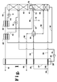
- Figure 1 is a simplified schematic representation of one preferred double column cryogenic rectification system wherein the process and apparatus of this invention may be employed.
- Figure 2 is a representation of one embodiment of a downflow reflux condenser useful in the practice of this invention.
- Figure 3 is a graphical representation of the advantages attainable by the practice of this invention compared with conventional double column cryogenic rectification practice.
- Figure 4 is a simplified schematic representation of another embodiment of the invention carried out in conjunction with a single column.
- the invention comprises an arrangement whereby the liquid head normally associated with the main condenser/reboiler of a double column system is eliminated.
- bottom liquid flows downward through a downflow reflux condenser and, once through, is removed without subsequently passing through the condenser.
- the liquid flows by gravity without need for liquid head pressure.
- the liquid is rectified as it passes downwardly through the downflow reflux condenser by the countercurrent direct contact flow of vapor generated by heat exchange of the downflowing liquid with higher pressure column shelf vapor.
- the combination of the elimination of the need for liquid head pressure at the condenser coupled with the rectification of the downwardly flowing liquid within the downflow reflux condenser serves to reduce the temperature of the shelf vapor required to effectively vaporize the bottom liquid.
- the temperature reduction translates into a pressure reduction thus enabling the higher pressure column to operate at a lower pressure than would otherwise be required for comparable performance.
- the lower operating pressure reduces the feed compression requirements thus reducing the operating costs for the system.
- feed air 24 which has been substantially cleaned of high boiling impurities such as water vapor and carbon dioxide, and which has been compressed to a pressure generally within the range of from 40 to 80 pounds per square inch absolute (psia), is divided into two streams 25 and 26. Both of these streams enter the warm end of primary heat exchanger 27 wherein they are cooled by indirect heat exchange with return streams.
- Stream 26 is divided at an intermediate point within primary heat exchanger 27 into main stream 29 and auxiliary stream 28.
- Main stream 29 completes the traverse of primary heat exchanger 27 and is passed into first column 40 which is the higher pressure column of a double column.
- Column 40 is operating at a pressure generally within the range of from 35 to 75 psia.
- Auxiliary stream 28 is removed from primary heat exchanger 27 after partial traverse and is turboexpanded by passage through turboexpander 30 to generate refrigeration.
- Resulting expanded stream 31 is passed into second column 42 which is the lower pressure column of the aforesaid double column.
- Column 42 is operating at a pressure less than that of column 40 and generally within the range of from 15 to 25 psia.
- Stream 25 is cooled by passage through primary heat exchanger 27 and resulting stream 34 is passed into product boiler 35 wherein it is at least partially condensed by indirect heat exchange with oxygen-richer liquid as will be further described later.
- Resulting stream 36 is passed into column 40 generally above the point where stream 29 is passed into column 40.
- a portion 72 of the nitrogen-enriched liquid is returned to column 40 as reflux.
- Another portion 33 of the nitrogen-enriched liquid is passed through heat exchanger 49 wherein it is subcooled by indirect heat exchange with a return stream.
- Resulting stream 44 is expanded through valve 11 and passed into column 42 as reflux.
- Nitrogen-rich vapor having a nitrogen concentration of at least 90 mole percent, is withdrawn from the upper portion of column 42 in line 45 and warmed by passage through heat exchangers 49, 48 and 27. Resulting stream 50 is removed from the system and, if desired, may be recovered as product nitrogen.
- the oxygen-rich liquid has an oxygen concentration of at least 50 mole percent and generally within the range of from 80 to 95 percent.
- the oxygen-rich liquid is passed into the upper portion of downflow reflux condenser 41 as shown by flow lines 74 in Figure 2 which is an enlarged view of one embodiment of the downflow reflux condenser.
- the numerals in Figure 2 correspond to those of Figure 1 for the common elements.
- As oxygen-rich liquid flows down downflow reflux condenser 41 it is partially vaporized by indirect heat exchange with the aforesaid condensing nitrogen-enriched vapor to produce oxygen-rich vapor.
- from about 70 to 85 percent of the downflowing oxygen-rich liquid is vaporized within the downflow reflux condenser.
- the resulting oxygen-rich vapor flows upwardly through downflow reflux condenser 41 in countercurrent direct contact flow with the downflowing oxygen-rich liquid.
- the countercurrent direct contact flow of the oxygen-rich liquid and the oxygen-rich vapor within the downflow reflux condenser causes rectification to occur wherein more volatile component, e.g. nitrogen, is passed from the liquid into the vapor and less volatile component, e.g. oxygen, is passed from the vapor into the liquid.
- the resulting oxygen-rich vapor is passed out from the upper portion of downflow reflux condenser 41, as depicted by arrows 75, having an oxygen concentration which is less than that of the oxygen-rich liquid as it passes into the downflow reflux condenser. This vapor is then passed up column 42 as vapor upflow for the rectification.
- the rectification within downflow reflux condenser 41 produces oxygen-richer liquid which has an oxygen concentration which exceeds the oxygen concentration of the oxygen-rich liquid, generally by at least 3 mole percent and typically by at least 5 mole percent.
- the oxygen-richer liquid passes out of the rectifying section of downflow reflux condenser 41 as depicted by arrows 76 and is withdrawn from the lower portion of downflow reflux condenser 41 in line 37.
- the oxygen-richer liquid is passed into product boiler 35 wherein it is vaporized by indirect heat exchange with feed air.
- Product boiler 35 may comprise a downflow reflux condenser or a conventional pool boiling condenser.
- Resulting oxygen-richer vapor stream 38 is passed from product boiler 35, through primary heat exchanger 27 and recovered as product oxygen stream 39 having an oxygen concentration generally within the range of from 70 to 98 mole percent.
- Figure 3 graphically illustrates the advantages attainable with the practice of the invention compared to conventional practice employing a pool boiling condenser. Lines A report the results attained with the practice of the invention while lines B report the results attained with conventional practice.
- the liquid to be vaporized enters at the top of the downflow reflux condenser (point 1 of lines A) and is at the column pressure of 16.5 psia with an oxygen purity of about 80 mole percent.
- the oxygen-rich liquid exits at the bottom of the downflow reflux condenser at essentially the same pressure of 16.5 psia but at a higher oxygen purity of 90 mole percent (point 2 of lines A).
- the difference in the temperatures of A and B at point 1 is related to the different compositions.
- the invention allows more nitrogen in the oxygen at that point since it will be removed as it progresses through the downflow reflux condenser.
- the difference in the temperatures of A and B at point 2 is related to the different pressures, since the conventional practice operates at a higher pressure at that point.
- the corresponding nitrogen temperatures are then chosen to allow equivalent temperature differences for heat transfer for both processes.
- the practice of the invention leads to lower required temperatures and corresponding pressure levels for the high pressure column. As a result the required air feed pressure levels are lower.
- the invention may also be practiced in conjunction with a single column cryogenic rectification system.
- a single column cryogenic rectification system is illustrated in Figure 4.
- feed air 100 is passed into single column 101 where it is separated by cryogenic rectification into nitrogen-rich vapor and oxygen-enriched liquid.
- Column 101 is operating at a pressure generally within the range of from 40 to 250 psia.
- a liquid feed air stream 102 may also be passed into column 101.
- Oxygen-enriched liquid is passed through line 103 and expansion valve 104 into the upper portion of downflow reflux condenser 105.
- Nitrogen-rich vapor is passed into downflow reflux condenser 105 in line 106. A portion of nitrogen-rich vapor is taken from line 106 in line 107 and recovered as nitrogen product having a nitrogen concentration generally within the range of from 99 to 100 mole percent.
- downflow reflux condenser 105 a portion of the downflowing oxygen-enriched liquid is vaporized by indirect heat exchange with nitrogen-rich vapor producing oxygen-enriched vapor and nitrogen-rich liquid.
- the nitrogen-rich liquid is used as reflux for column 101 as illustrated by passage through line 108.
- the downflowing oxygen-enriched liquid is vaporized within the downflow reflux condenser.
- the resulting oxygen-enriched vapor flows upwardly through downflow reflux condenser 105 in countercurrent direct contact flow with the downflowing oxygen-enriched liquid.
- the countercurrent direct contact flow of the oxygen-enriched liquid and the oxygen-enriched vapor within the downflow reflux condenser causes rectification to occur wherein more volatile component, e.g. nitrogen, is passed from the liquid into the vapor and less volatile component, e.g. oxygen, is passed from the vapor into the liquid.
- the resulting oxygen-enriched vapor is passed out from the upper portion of downflow reflux condenser 105 having an oxygen concentration which is less than that of the oxygen-enriched liquid as it passes into the downflow reflux condenser. This vapor is then passed out as waste stream 109.
- the rectification within downflow reflux condenser 105 produces oxygen-richer liquid which has an oxygen concentration which exceeds the oxygen concentration of the oxygen-enriched liquid, generally by at least 3 mole percent and typically by at least 5 mole percent.
- the oxygen-richer liquid passes out of the rectifying section of downflow reflux condenser 105 and is withdrawn from the lower portion of downflow reflux condenser 105 in line 110 and recovered as product oxygen having an oxygen concentration within the range of from 40 to 75 mole percent. If desired, the oxygen richer liquid may be vaporized prior to being recovered.
- the invention has been discussed in detail with reference to certain preferred embodiments, those skilled in the art will recognize that there are other embodiments of the invention within the spirit and the scope of the claims.
- the invention may be used to produce oxygen of any desired purity.
- the invention may be practiced at higher operating pressures than those recited in the detailed description, and also may be used in a cycle having an argon sidearm column with the double column.
- the oxygen-richer liquid may be increased in pressure prior to vaporization in the product boiler; some oxygen-richer liquid may be recovered directly as liquid as shown by line 12 in Figure 1.
- nitrogen liquid may be recovered by extending a line from line 44 of Figure 1.
- Refrigeration for the system may be generated by the turboexpansion of a product or other return stream in addition to or in place of the turboexpansion of feed air. Higher purity nitrogen may be produced by adding another section or tophat to the lower pressure column.
Landscapes
- Engineering & Computer Science (AREA)
- Physics & Mathematics (AREA)
- Mechanical Engineering (AREA)
- Thermal Sciences (AREA)
- General Engineering & Computer Science (AREA)
- Separation By Low-Temperature Treatments (AREA)
Applications Claiming Priority (2)
| Application Number | Priority Date | Filing Date | Title |
|---|---|---|---|
| US103616 | 1993-08-06 | ||
| US10361693A | 1993-08-09 | 1993-08-09 |
Publications (1)
| Publication Number | Publication Date |
|---|---|
| EP0637725A1 true EP0637725A1 (de) | 1995-02-08 |
Family
ID=22296105
Family Applications (1)
| Application Number | Title | Priority Date | Filing Date |
|---|---|---|---|
| EP94112265A Withdrawn EP0637725A1 (de) | 1993-08-06 | 1994-08-05 | Kryogenisches Rektifikationssystem für Betrieb bei niedrigerem Druck |
Country Status (7)
| Country | Link |
|---|---|
| US (1) | US5410885A (de) |
| EP (1) | EP0637725A1 (de) |
| JP (1) | JPH0755333A (de) |
| KR (1) | KR950006406A (de) |
| CN (1) | CN1119733A (de) |
| BR (1) | BR9403176A (de) |
| CA (1) | CA2129596A1 (de) |
Cited By (3)
| Publication number | Priority date | Publication date | Assignee | Title |
|---|---|---|---|---|
| EP0921366A1 (de) * | 1997-12-02 | 1999-06-09 | Praxair Technology, Inc. | Kryogenische Zerlegunganlage mit einem Rücklaufkondensator zur Herstellung von niedrigreinem Sauerstoff |
| WO1999061854A1 (en) * | 1998-05-22 | 1999-12-02 | L'air Liquide, Societe Anonyme Pour L'etude Et, L'exploitation Des Procedes Georges Claude | Process and apparatus for the production of nitrogen by cryogenic distillation using a dephlegmator |
| EP1050729A1 (de) * | 1999-05-04 | 2000-11-08 | Praxair Technology, Inc. | Tieftemperaturluftzerlegungsanlage mit einem Dephlegmator |
Families Citing this family (35)
| Publication number | Priority date | Publication date | Assignee | Title |
|---|---|---|---|---|
| US5592832A (en) * | 1995-10-03 | 1997-01-14 | Air Products And Chemicals, Inc. | Process and apparatus for the production of moderate purity oxygen |
| US5946942A (en) * | 1998-08-05 | 1999-09-07 | Praxair Technology, Inc. | Annular column for cryogenic rectification |
| US6212906B1 (en) | 2000-02-16 | 2001-04-10 | Praxair Technology, Inc. | Cryogenic reflux condenser system for producing oxygen-enriched air |
| US6295836B1 (en) | 2000-04-14 | 2001-10-02 | Praxair Technology, Inc. | Cryogenic air separation system with integrated mass and heat transfer |
| US6237366B1 (en) | 2000-04-14 | 2001-05-29 | Praxair Technology, Inc. | Cryogenic air separation system using an integrated core |
| JP4577977B2 (ja) * | 2000-11-14 | 2010-11-10 | 大陽日酸株式会社 | 空気液化分離方法及び装置 |
| US6351969B1 (en) | 2001-01-31 | 2002-03-05 | Praxair Technology, Inc. | Cryogenic nitrogen production system using a single brazement |
| DE10161584A1 (de) * | 2001-12-14 | 2003-06-26 | Linde Ag | Vorrichtung und Verfahren zur Erzeugung gasförmigen Sauerstoffs unter erhöhtem Druck |
| US6694775B1 (en) * | 2002-12-12 | 2004-02-24 | Air Products And Chemicals, Inc. | Process and apparatus for the recovery of krypton and/or xenon |
| US7114352B2 (en) * | 2003-12-24 | 2006-10-03 | Praxair Technology, Inc. | Cryogenic air separation system for producing elevated pressure nitrogen |
| US7210312B2 (en) * | 2004-08-03 | 2007-05-01 | Sunpower, Inc. | Energy efficient, inexpensive extraction of oxygen from ambient air for portable and home use |
| EP1715267A1 (de) * | 2005-04-22 | 2006-10-25 | Air Products And Chemicals, Inc. | Zweistufige Abscheidung von Stickstoff aus verflüssigtem Erdgas |
| US7421856B2 (en) * | 2005-06-17 | 2008-09-09 | Praxair Technology, Inc. | Cryogenic air separation with once-through main condenser |
| FR2895069B1 (fr) * | 2005-12-20 | 2014-01-31 | Air Liquide | Appareil de separation d'air par distillation cryogenique |
| US9933207B2 (en) | 2009-02-17 | 2018-04-03 | Ortloff Engineers, Ltd. | Hydrocarbon gas processing |
| EA022672B1 (ru) | 2009-02-17 | 2016-02-29 | Ортлофф Инджинирс, Лтд. | Обработка углеводородного газа |
| US9939195B2 (en) | 2009-02-17 | 2018-04-10 | Ortloff Engineers, Ltd. | Hydrocarbon gas processing including a single equipment item processing assembly |
| US9080811B2 (en) | 2009-02-17 | 2015-07-14 | Ortloff Engineers, Ltd | Hydrocarbon gas processing |
| US9074814B2 (en) | 2010-03-31 | 2015-07-07 | Ortloff Engineers, Ltd. | Hydrocarbon gas processing |
| US9052137B2 (en) | 2009-02-17 | 2015-06-09 | Ortloff Engineers, Ltd. | Hydrocarbon gas processing |
| MY157703A (en) | 2009-06-11 | 2016-07-15 | Ortloff Engineers Ltd | Hydrocarbon gas processing |
| FR2947898A1 (fr) * | 2009-07-10 | 2011-01-14 | Air Liquide | Procede de separation d'air par distillation cryogenique |
| US9057558B2 (en) | 2010-03-31 | 2015-06-16 | Ortloff Engineers, Ltd. | Hydrocarbon gas processing including a single equipment item processing assembly |
| US9068774B2 (en) | 2010-03-31 | 2015-06-30 | Ortloff Engineers, Ltd. | Hydrocarbon gas processing |
| CN102213537A (zh) * | 2011-04-18 | 2011-10-12 | 开封黄河空分集团有限公司 | 低压富氧空气分离工艺 |
| CN102506559A (zh) * | 2011-09-28 | 2012-06-20 | 开封东京空分集团有限公司 | 多段精馏制取高纯氮气空分工艺 |
| CN102721261B (zh) * | 2012-04-26 | 2014-11-05 | 上海启元空分技术发展股份有限公司 | 一种返流膨胀制冷生产带压低纯氧和高纯氮的方法 |
| JP6591983B2 (ja) | 2013-09-11 | 2019-10-16 | オートロフ・エンジニアーズ・リミテッド | 炭化水素ガス処理 |
| US9790147B2 (en) | 2013-09-11 | 2017-10-17 | Ortloff Engineers, Ltd. | Hydrocarbon processing |
| WO2015038287A1 (en) | 2013-09-11 | 2015-03-19 | Ortloff Engineers, Ltd. | Hydrocarbon gas processing |
| US10551118B2 (en) | 2016-08-26 | 2020-02-04 | Ortloff Engineers, Ltd. | Hydrocarbon gas processing |
| US10551119B2 (en) | 2016-08-26 | 2020-02-04 | Ortloff Engineers, Ltd. | Hydrocarbon gas processing |
| US10533794B2 (en) | 2016-08-26 | 2020-01-14 | Ortloff Engineers, Ltd. | Hydrocarbon gas processing |
| US11428465B2 (en) | 2017-06-01 | 2022-08-30 | Uop Llc | Hydrocarbon gas processing |
| US11543180B2 (en) | 2017-06-01 | 2023-01-03 | Uop Llc | Hydrocarbon gas processing |
Citations (3)
| Publication number | Priority date | Publication date | Assignee | Title |
|---|---|---|---|---|
| DE849850C (de) * | 1944-01-27 | 1952-09-18 | Adolf Messer G M B H | Verfahren zur Zerlegung von Luft |
| DE3035844A1 (de) * | 1980-09-23 | 1982-05-06 | Linde Ag, 6200 Wiesbaden | Verfahren und vorrichtung zur gewinnung von sauerstoff mittlerer reinheit |
| EP0384483A2 (de) * | 1989-02-23 | 1990-08-29 | Linde Aktiengesellschaft | Verfahren und Vorrichtung zur Luftzerlegung durch Rektifikation |
Family Cites Families (12)
| Publication number | Priority date | Publication date | Assignee | Title |
|---|---|---|---|---|
| US3034306A (en) * | 1959-06-05 | 1962-05-15 | British Oxygen Co Ltd | Separation of air |
| US3236059A (en) * | 1962-08-29 | 1966-02-22 | Air Prod & Chem | Separation of gaseous mixtures |
| US3559722A (en) * | 1969-09-16 | 1971-02-02 | Trane Co | Method and apparatus for two-phase heat exchange fluid distribution in plate-type heat exchangers |
| DE2557453C2 (de) * | 1975-12-19 | 1982-08-12 | Linde Ag, 6200 Wiesbaden | Verfahren zur Gewinnung von gasförmigem Sauerstoff |
| GB2080929B (en) * | 1980-07-22 | 1984-02-08 | Air Prod & Chem | Producing gaseous oxygen |
| USRE33026E (en) * | 1983-06-24 | 1989-08-22 | L'air Liquide, Societe Anonyme Pour L'etude Et L'exploitation Des Procedes Georges Claude | Process and device for vaporizing a liquid by heat exchange with a second fluid and their application in an air distillation installation |
| US4560398A (en) * | 1984-07-06 | 1985-12-24 | Union Carbide Corporation | Air separation process to produce elevated pressure oxygen |
| US4732597A (en) * | 1986-04-22 | 1988-03-22 | The United States Of America As Represented By The United States Department Of Energy | Low energy consumption method for separating gaseous mixtures and in particular for medium purity oxygen production |
| US4704147A (en) * | 1986-08-20 | 1987-11-03 | Air Products And Chemicals, Inc. | Dual air pressure cycle to produce low purity oxygen |
| GB8719349D0 (en) * | 1987-08-14 | 1987-09-23 | Boc Group Ltd | Liquefied gas boilers |
| FR2665755B1 (fr) * | 1990-08-07 | 1993-06-18 | Air Liquide | Appareil de production d'azote. |
| US5122174A (en) * | 1991-03-01 | 1992-06-16 | Air Products And Chemicals, Inc. | Boiling process and a heat exchanger for use in the process |
-
1993
- 1993-08-06 US US08/103,016 patent/US5410885A/en not_active Expired - Fee Related
-
1994
- 1994-08-05 CN CN94115024A patent/CN1119733A/zh active Pending
- 1994-08-05 CA CA002129596A patent/CA2129596A1/en not_active Abandoned
- 1994-08-05 JP JP6203035A patent/JPH0755333A/ja not_active Withdrawn
- 1994-08-05 EP EP94112265A patent/EP0637725A1/de not_active Withdrawn
- 1994-08-05 KR KR1019940019335A patent/KR950006406A/ko not_active Withdrawn
- 1994-08-05 BR BR9403176A patent/BR9403176A/pt not_active Application Discontinuation
Patent Citations (3)
| Publication number | Priority date | Publication date | Assignee | Title |
|---|---|---|---|---|
| DE849850C (de) * | 1944-01-27 | 1952-09-18 | Adolf Messer G M B H | Verfahren zur Zerlegung von Luft |
| DE3035844A1 (de) * | 1980-09-23 | 1982-05-06 | Linde Ag, 6200 Wiesbaden | Verfahren und vorrichtung zur gewinnung von sauerstoff mittlerer reinheit |
| EP0384483A2 (de) * | 1989-02-23 | 1990-08-29 | Linde Aktiengesellschaft | Verfahren und Vorrichtung zur Luftzerlegung durch Rektifikation |
Cited By (3)
| Publication number | Priority date | Publication date | Assignee | Title |
|---|---|---|---|---|
| EP0921366A1 (de) * | 1997-12-02 | 1999-06-09 | Praxair Technology, Inc. | Kryogenische Zerlegunganlage mit einem Rücklaufkondensator zur Herstellung von niedrigreinem Sauerstoff |
| WO1999061854A1 (en) * | 1998-05-22 | 1999-12-02 | L'air Liquide, Societe Anonyme Pour L'etude Et, L'exploitation Des Procedes Georges Claude | Process and apparatus for the production of nitrogen by cryogenic distillation using a dephlegmator |
| EP1050729A1 (de) * | 1999-05-04 | 2000-11-08 | Praxair Technology, Inc. | Tieftemperaturluftzerlegungsanlage mit einem Dephlegmator |
Also Published As
| Publication number | Publication date |
|---|---|
| JPH0755333A (ja) | 1995-03-03 |
| CN1119733A (zh) | 1996-04-03 |
| KR950006406A (ko) | 1995-03-21 |
| CA2129596A1 (en) | 1995-02-07 |
| US5410885A (en) | 1995-05-02 |
| BR9403176A (pt) | 1995-04-11 |
Similar Documents
| Publication | Publication Date | Title |
|---|---|---|
| US5410885A (en) | Cryogenic rectification system for lower pressure operation | |
| US5440884A (en) | Cryogenic air separation system with liquid air stripping | |
| EP0567047B1 (de) | Kryogenisches Rektifikationssystem mit Dreifachkolonne | |
| US5463871A (en) | Side column cryogenic rectification system for producing lower purity oxygen | |
| US5655388A (en) | Cryogenic rectification system for producing high pressure gaseous oxygen and liquid product | |
| EP0841524B1 (de) | Kryogenisches Rektifiziersystem mit einer Sumpfflüssigkeitskolonne | |
| US5337570A (en) | Cryogenic rectification system for producing lower purity oxygen | |
| US5469710A (en) | Cryogenic rectification system with enhanced argon recovery | |
| EP0594214B1 (de) | Kryogenisches Rektifikationsverfahren mit thermisch integrierter Argonkolonne | |
| US5546767A (en) | Cryogenic rectification system for producing dual purity oxygen | |
| US5263327A (en) | High recovery cryogenic rectification system | |
| EP0682219A1 (de) | Luftkochendes kryogenes Rektifikationsverfahren zur Herstellung von Hochdrucksauerstoff | |
| EP0848218B1 (de) | Kryogenisches Rektifikationssystem zur Herstellung von Sauerstoff niedrigerer und höherer Reinheit | |
| US5916262A (en) | Cryogenic rectification system for producing low purity oxygen and high purity oxygen | |
| EP0959313B1 (de) | Kryogenisches Rektifikationssystem mit integriertem Phasentrenner mit Produktkocher | |
| EP0824209B1 (de) | Kryogenisches Rektifikationssystem mit Seitenkolonne zur Herstellung von Sauerstoff niedrigerer Reinheit und hochreinem Stickstoff | |
| CA2196353C (en) | Single column cryogenic rectification system for lower purity oxygen production | |
| EP0540901A1 (de) | Kryogenisches Rektifikationssystem mit verbesserter Gewinnung von Sauerstoff | |
| US5878597A (en) | Cryogenic rectification system with serial liquid air feed | |
| US5666824A (en) | Cryogenic rectification system with staged feed air condensation | |
| EP0848219B1 (de) | Kryogenisches Rektifikationssystem zur Herstellung von Argon und Sauerstoff niedriger Reinheit | |
| US6073462A (en) | Cryogenic air separation system for producing elevated pressure oxygen | |
| US5806342A (en) | Cryogenic rectification system for producing low purity oxygen and high purity oxygen |
Legal Events
| Date | Code | Title | Description |
|---|---|---|---|
| PUAI | Public reference made under article 153(3) epc to a published international application that has entered the european phase |
Free format text: ORIGINAL CODE: 0009012 |
|
| AK | Designated contracting states |
Kind code of ref document: A1 Designated state(s): BE DE ES FR GB IT NL |
|
| 17P | Request for examination filed |
Effective date: 19950329 |
|
| 17Q | First examination report despatched |
Effective date: 19960319 |
|
| STAA | Information on the status of an ep patent application or granted ep patent |
Free format text: STATUS: THE APPLICATION IS DEEMED TO BE WITHDRAWN |
|
| 18D | Application deemed to be withdrawn |
Effective date: 19960730 |