EP0637730A1 - Codeur angulaire resp. détecteur de positions angulaire resp. générateur d'impulsions rotationel - Google Patents
Codeur angulaire resp. détecteur de positions angulaire resp. générateur d'impulsions rotationel Download PDFInfo
- Publication number
- EP0637730A1 EP0637730A1 EP94111913A EP94111913A EP0637730A1 EP 0637730 A1 EP0637730 A1 EP 0637730A1 EP 94111913 A EP94111913 A EP 94111913A EP 94111913 A EP94111913 A EP 94111913A EP 0637730 A1 EP0637730 A1 EP 0637730A1
- Authority
- EP
- European Patent Office
- Prior art keywords
- angular
- raster
- angular position
- angle
- interference
- Prior art date
- Legal status (The legal status is an assumption and is not a legal conclusion. Google has not performed a legal analysis and makes no representation as to the accuracy of the status listed.)
- Withdrawn
Links
- 230000005693 optoelectronics Effects 0.000 claims description 2
- 210000000056 organ Anatomy 0.000 claims 1
- 230000001105 regulatory effect Effects 0.000 claims 1
- 230000000737 periodic effect Effects 0.000 abstract 1
- 238000005259 measurement Methods 0.000 description 5
- 238000000034 method Methods 0.000 description 5
- 238000003860 storage Methods 0.000 description 4
- 230000008033 biological extinction Effects 0.000 description 3
- 230000014509 gene expression Effects 0.000 description 3
- 238000004519 manufacturing process Methods 0.000 description 3
- 239000002184 metal Substances 0.000 description 3
- 230000001066 destructive effect Effects 0.000 description 2
- 238000005530 etching Methods 0.000 description 2
- 230000003287 optical effect Effects 0.000 description 2
- 238000003825 pressing Methods 0.000 description 2
- 239000000969 carrier Substances 0.000 description 1
- 230000001427 coherent effect Effects 0.000 description 1
- 230000001419 dependent effect Effects 0.000 description 1
- 238000001514 detection method Methods 0.000 description 1
- 238000011161 development Methods 0.000 description 1
- 230000008020 evaporation Effects 0.000 description 1
- 238000001704 evaporation Methods 0.000 description 1
- 239000011521 glass Substances 0.000 description 1
- 238000005286 illumination Methods 0.000 description 1
- 230000001939 inductive effect Effects 0.000 description 1
- 238000012545 processing Methods 0.000 description 1
- 230000003068 static effect Effects 0.000 description 1
Images


Classifications
-
- G—PHYSICS
- G01—MEASURING; TESTING
- G01D—MEASURING NOT SPECIALLY ADAPTED FOR A SPECIFIC VARIABLE; ARRANGEMENTS FOR MEASURING TWO OR MORE VARIABLES NOT COVERED IN A SINGLE OTHER SUBCLASS; TARIFF METERING APPARATUS; MEASURING OR TESTING NOT OTHERWISE PROVIDED FOR
- G01D5/00—Mechanical means for transferring the output of a sensing member; Means for converting the output of a sensing member to another variable where the form or nature of the sensing member does not constrain the means for converting; Transducers not specially adapted for a specific variable
- G01D5/26—Mechanical means for transferring the output of a sensing member; Means for converting the output of a sensing member to another variable where the form or nature of the sensing member does not constrain the means for converting; Transducers not specially adapted for a specific variable characterised by optical transfer means, i.e. using infrared, visible, or ultraviolet light
- G01D5/32—Mechanical means for transferring the output of a sensing member; Means for converting the output of a sensing member to another variable where the form or nature of the sensing member does not constrain the means for converting; Transducers not specially adapted for a specific variable characterised by optical transfer means, i.e. using infrared, visible, or ultraviolet light with attenuation or whole or partial obturation of beams of light
- G01D5/34—Mechanical means for transferring the output of a sensing member; Means for converting the output of a sensing member to another variable where the form or nature of the sensing member does not constrain the means for converting; Transducers not specially adapted for a specific variable characterised by optical transfer means, i.e. using infrared, visible, or ultraviolet light with attenuation or whole or partial obturation of beams of light the beams of light being detected by photocells
-
- G—PHYSICS
- G01—MEASURING; TESTING
- G01D—MEASURING NOT SPECIALLY ADAPTED FOR A SPECIFIC VARIABLE; ARRANGEMENTS FOR MEASURING TWO OR MORE VARIABLES NOT COVERED IN A SINGLE OTHER SUBCLASS; TARIFF METERING APPARATUS; MEASURING OR TESTING NOT OTHERWISE PROVIDED FOR
- G01D2205/00—Indexing scheme relating to details of means for transferring or converting the output of a sensing member
- G01D2205/70—Position sensors comprising a moving target with particular shapes, e.g. of soft magnetic targets
- G01D2205/77—Specific profiles
- G01D2205/777—Whorl-shaped profiles
Definitions
- the invention relates to angular encoders, angular position encoders or angular momentum encoders, which essentially consist of a disk with raster structures.
- the resolution should be at least 32,000 angular steps per revolution.
- the angular position should be determinable without the object being moved after the sensor power supply is switched on (absolute angular measurement).
- the angular position should be determinable when the measurement object is stationary and also when it is rotating.
- the angular positions are suitably coded on a rotatable body (e.g. a disk) and read out and decoded by a stationary optical sensor system arranged opposite the rotating body. Due to the high angular resolution, the geometrical dimensions of the markings of the code are in the range of the light wavelength. For reading the code, diffraction and interference principles for illumination with coherent light can therefore be considered as a further development of the known coding disks.
- Suitable sensors for this task are rotary encoders which emit a certain number of pulses for each change in position.
- the maximum number of pulses per revolution of the rotary encoder is also specified. With conventional designs of around 80 mm, it is around 5000 pulses per revolution. Higher resolutions are only possible using special processes (interference grids etc.). These processes require a great deal of technical effort and are therefore of a larger and significantly more expensive type.
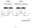
- Another known method is the use of an audio CD. This has depressions of depth ⁇ / 4, whereby the beam diameter must not be larger than the cross section of a depression.
- This principle is not suitable for absolute angle measurements, since the coded information can only be read out at recess edges.
- the angular position must be able to be determined without error in any position of the stationary and moving coding disk without any prior information about neighboring angular states or about the history.
- Each bit is therefore encoded in a grid, the grid structure having to be finer than the beam diameter of the light beam being read out.
- the grid fields are each formed in one of two possible textures for the two logical states I and O. These two textures must differ significantly in their properties with regard to interference and / or diffraction.
- One of the alternatives is a planar surface for state O and a grid pattern for state I.
- the light beam has to detect several depressions in each position. It is then possible for the beam area to have destructive interference in every beam position with the same proportion of the area of the depression area and the non-recessed area. Since the laser beam should remain optimally focused due to the required angular resolution, the structure size of the grooves must be reduced to a minimum.
- a coding state now consists geometrically per bit of information from a stripe pattern and no longer from a single depression.
- the total area for a bit is called a grid.
- the total area of the depression per bit and the total area of the non-recessed areas per bit must be approximately the same. At least one recess must be provided for each bit of information, which in this limit case must have half the beam area.
- Each angular position is coded in binary form in an angular word, a concentric circular ring of the disk being assigned to each bit position of the binary angular words and a circular segment of the disk being assigned to each angular word.
- Each bit of an angle word is encoded in a grid. The grids are rotated in the direction of rotation Radial rays and limited in the radial direction by circumferential lines.
- Each grid is planar for one binary value (e.g. 0) and crossed for the other binary value (e.g. 1) by grooves of depth ⁇ / 4.
- the grooves are arranged in the radial direction, so that the higher order diffraction maxima are not deflected radially in the direction of other tracks but tangentially.
- exemplary embodiments use interference and diffraction on the grating without using the reflection from the ⁇ / 4 depressions, so that the depressions can have almost any depth profile (except planar).
- the grid fields may also have a substructure.
- the stripe patterns can be composed globally of a spiral. However, care must be taken to ensure that no higher diffraction orders arise which illuminate radially adjacent phototransistors.
- the coding is applied to a disk with a diameter of 40 mm in the radius range between 15 mm and 20 mm.
- the present invention makes use of the possibility of using compact storage disks as coding disks and their large number of information carriers or exploit pits. It is obvious that such a storage medium that can be used on any of the known drives achieves resolutions that were not possible with previously known methods. Another advantage is the variability of the possible uses, namely to implement different electrical designs in a single device.
- the surface of the disk is also divided into a plurality of individual fields according to the invention. These fields are delimited by radial rays in the circumferential direction and by circular lines or spiral lines in the radial direction. There are two types of fields here, those which have a flat surface, ie have not been changed starting from the manufacture of the pane, and grid fields which have a structure within their limits so that a light beam directed into this region is diffracted or Shows interference. Several such fields lie alternately next to one another in the circumferential direction or in the spiral direction and can be scanned with the aid of a light beam and a photodiode. Such a system is available for each individual track.
- a unique, multi-digit digital number can be assigned to each rotary position of the disk using a number of sensors that correspond to the proportion of the tracks. The sensing of such a rotational position is not dependent on the disk rotating with respect to the light source. Even in the standstill position, a digital number can be derived for each individual track, which corresponds to a single specific rotational position of the disk.
- the principle of the audio CD is outlined in FIG. 1.
- the depressions are exactly ⁇ / 4 deep, so that extinction occurs as soon as half of the light beam enters the depression meets. However, this is only briefly the case when entering and leaving the depression and is therefore unsuitable for static reading.
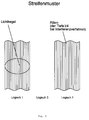
- the proposal according to the invention is now to provide the coded disk with a stripe pattern for one logical state and to leave it as a flat surface for the other logical state.
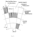
- the stripe width may not exceed half the beam diameter (Fig. 2).
- the strips can read out several traces of the disc at the same time along the radius of the disc. For this, the distance between the strips is greater at the outer edge than at the inner edge of the coded area.
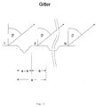
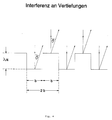
- the first is based on ⁇ / 4 depressions and interference, the other on diffraction at the grating.
- the CD surface according to FIG. 3 is realized as a grating, the light is reflected on the flat surface and is subject to the laws of diffraction and interference. The following applies to the intensity
- the first expression in brackets describes the diffraction for each raised bar and the second describes the interference between the N bars. Observation is made in the direction of the first diffraction order, namely darkness without grating and brightness above grating areas. However, the maximum intensity is only 4.5% of the intensity in the O diffraction order.
- the observation angle ⁇ is not critical with regard to extinction.
- the intensity is only 5% even at 45 °.
- FIGS. 6 and 7 A compact storage disk and a laser are shown in the middle of FIGS. 6 and 7. In the embodiment shown in FIG. 6, the scanning takes place from the inside out. the track with the pits being designed as a spiral.
- the laser is stationary, the track used is a concentric ring.
- FIGS. 6 and 7 schematically show the take-off system with a sensor, semi-transparent mirror and laser. It is any known system which therefore need not be described further.
Landscapes
- Physics & Mathematics (AREA)
- General Physics & Mathematics (AREA)
- Optical Transform (AREA)
- Laser Surgery Devices (AREA)
- Instruments For Viewing The Inside Of Hollow Bodies (AREA)
Applications Claiming Priority (2)
| Application Number | Priority Date | Filing Date | Title |
|---|---|---|---|
| DE9311472U | 1993-07-31 | ||
| DE9311472U DE9311472U1 (de) | 1993-07-31 | 1993-07-31 | Drehimpulsgeber mit Laserabtastung |
Publications (1)
| Publication Number | Publication Date |
|---|---|
| EP0637730A1 true EP0637730A1 (fr) | 1995-02-08 |
Family
ID=6896274
Family Applications (1)
| Application Number | Title | Priority Date | Filing Date |
|---|---|---|---|
| EP94111913A Withdrawn EP0637730A1 (fr) | 1993-07-31 | 1994-07-29 | Codeur angulaire resp. détecteur de positions angulaire resp. générateur d'impulsions rotationel |
Country Status (2)
| Country | Link |
|---|---|
| EP (1) | EP0637730A1 (fr) |
| DE (1) | DE9311472U1 (fr) |
Cited By (4)
| Publication number | Priority date | Publication date | Assignee | Title |
|---|---|---|---|---|
| WO2005071363A1 (fr) * | 2004-01-26 | 2005-08-04 | Hahn-Schickard- Gesellschaft Für Angewandte Forschune E.V. | Transducteur rotatif et procede pour le faire fonctionner |
| WO2007048611A1 (fr) * | 2005-10-28 | 2007-05-03 | Hahn-Schickard-Gesellschaft für angewandte Forschung e.V. | Élément de codage pour transmetteur de position |
| WO2015101433A1 (fr) | 2014-01-06 | 2015-07-09 | Ebs Ink-Jet Systeme Gmbh | Imprimante à jet d'encre équipée d'un appareil portable pour imprimer un produit ainsi que procédé d'impression d'un produit |
| DE102023100826A1 (de) * | 2023-01-16 | 2024-01-25 | Schaeffler Technologies AG & Co. KG | Drehwinkelmesseinrichtung, Getriebeeinheit, Gelenkmodul und Verfahren |
Families Citing this family (1)
| Publication number | Priority date | Publication date | Assignee | Title |
|---|---|---|---|---|
| DE19543483A1 (de) * | 1995-11-22 | 1997-05-28 | Hannes Weigel | Verfahren und Vorrichtung zum Messen von Winkeln |
Citations (4)
| Publication number | Priority date | Publication date | Assignee | Title |
|---|---|---|---|---|
| US3482107A (en) * | 1966-07-26 | 1969-12-02 | Leitz Ernst Gmbh | Photoelectric position sensing device comprising light diffracting phase gratings using polarizer beam splitters for sensing the time phase position of the gratings |
| FR2075408A5 (fr) * | 1970-01-27 | 1971-10-08 | Leitz Ernst Gmbh | |
| EP0096476A2 (fr) * | 1982-05-13 | 1983-12-21 | Benson, Inc. | Grille de diffraction linéaire plane pour conversion optique d'information |
| EP0390092A2 (fr) * | 1989-03-28 | 1990-10-03 | Canon Kabushiki Kaisha | Codeur |
-
1993
- 1993-07-31 DE DE9311472U patent/DE9311472U1/de not_active Expired - Lifetime
-
1994
- 1994-07-29 EP EP94111913A patent/EP0637730A1/fr not_active Withdrawn
Patent Citations (4)
| Publication number | Priority date | Publication date | Assignee | Title |
|---|---|---|---|---|
| US3482107A (en) * | 1966-07-26 | 1969-12-02 | Leitz Ernst Gmbh | Photoelectric position sensing device comprising light diffracting phase gratings using polarizer beam splitters for sensing the time phase position of the gratings |
| FR2075408A5 (fr) * | 1970-01-27 | 1971-10-08 | Leitz Ernst Gmbh | |
| EP0096476A2 (fr) * | 1982-05-13 | 1983-12-21 | Benson, Inc. | Grille de diffraction linéaire plane pour conversion optique d'information |
| EP0390092A2 (fr) * | 1989-03-28 | 1990-10-03 | Canon Kabushiki Kaisha | Codeur |
Non-Patent Citations (1)
| Title |
|---|
| C. DURING, S. ANDERSSON, J. WILKANDER: "Non-contact absolute position measurement using a compact disc player optical pick-up", SENSORS AND ACTUATORS, vol. A32, no. 1/3, April 1992 (1992-04-01), LAUSANNE, CH, pages 575 - 581, XP000287376, DOI: doi:10.1016/0924-4247(92)80046-6 * |
Cited By (4)
| Publication number | Priority date | Publication date | Assignee | Title |
|---|---|---|---|---|
| WO2005071363A1 (fr) * | 2004-01-26 | 2005-08-04 | Hahn-Schickard- Gesellschaft Für Angewandte Forschune E.V. | Transducteur rotatif et procede pour le faire fonctionner |
| WO2007048611A1 (fr) * | 2005-10-28 | 2007-05-03 | Hahn-Schickard-Gesellschaft für angewandte Forschung e.V. | Élément de codage pour transmetteur de position |
| WO2015101433A1 (fr) | 2014-01-06 | 2015-07-09 | Ebs Ink-Jet Systeme Gmbh | Imprimante à jet d'encre équipée d'un appareil portable pour imprimer un produit ainsi que procédé d'impression d'un produit |
| DE102023100826A1 (de) * | 2023-01-16 | 2024-01-25 | Schaeffler Technologies AG & Co. KG | Drehwinkelmesseinrichtung, Getriebeeinheit, Gelenkmodul und Verfahren |
Also Published As
| Publication number | Publication date |
|---|---|
| DE9311472U1 (de) | 1993-12-02 |
Similar Documents
| Publication | Publication Date | Title |
|---|---|---|
| DE3844704C2 (fr) | ||
| DE60301538T2 (de) | Periodische Skala mit integriertem Code für absoluten Positionsgeber | |
| DE2508153C3 (de) | Optisches Lesegerät | |
| DE69113415T2 (de) | Positionskodierer für Linear- oder Winkelmessapparat. | |
| EP0160811B1 (fr) | Dispositif de mesure photo-électrique | |
| DE2503038A1 (de) | Optisches informationslesesystem | |
| EP1407231B1 (fr) | Dispositif de mesure de position | |
| DE4209149C2 (de) | Verschiebungsdetektoren zum Detektieren zweidimensionaler Verschiebungen | |
| DE69622297T2 (de) | Vorrichtung zur Bestimmung einer Verschiebung und deren Verwendung in einer Einrichtung zur Antriebsregelung | |
| DE9116717U1 (de) | Interferentielle Positionsmeßvorrichtung | |
| DE3127116C3 (de) | Meßsystem zum berührungslosen Erfassen von Positionen bei einer Kolben-Zylinder-Einheit | |
| EP2063230B1 (fr) | Dispositif optique de mesure de la position | |
| DE69424003T2 (de) | Optische Platte, Gerät zur Wiedergabe für optische Platte, und Verfahren zur Aufzeichnung/Wiedergabe für optische Platte | |
| DE2601693B2 (de) | Verfahren zur Herstellung eines Dokuments und Vorrichtung zur Durchführung des Verfahrens | |
| DE19855064B4 (de) | Lenkwinkelsensor | |
| EP0718834B1 (fr) | Support de données optique et appareil de lecture d'un tel support de données | |
| DE19937023A1 (de) | Reflexions-Maßverkörperung und Verfahren zur Herstellung einer Reflexions-Maßverkörperung | |
| EP0060937B1 (fr) | Arrangement pour représenter le résultat d'un comptage d'un compteur à tambour sous la forme de signaux électriques | |
| WO2004010170A1 (fr) | Determination optique de position ou de longueur | |
| WO2009115179A2 (fr) | Appareil de mesure et dispositif de détection de variations de position | |
| DE3046720A1 (de) | Positions-kodierer | |
| DE3742485C2 (fr) | ||
| DE4025055B4 (de) | Positionsauslesevorrichtung, insbesondere für Maschinen- und Drehtisch-Steuerungen | |
| CH589326A5 (en) | Data recognition system using optical sensor - has diffraction gratings on data plate with retro-reflective backing plate and photoelectric pickup | |
| EP1770372B1 (fr) | Dispositif de mesure de position |
Legal Events
| Date | Code | Title | Description |
|---|---|---|---|
| PUAI | Public reference made under article 153(3) epc to a published international application that has entered the european phase |
Free format text: ORIGINAL CODE: 0009012 |
|
| AK | Designated contracting states |
Kind code of ref document: A1 Designated state(s): AT BE CH DE DK ES FR GB GR IE IT LI LU MC NL PT SE |
|
| STAA | Information on the status of an ep patent application or granted ep patent |
Free format text: STATUS: THE APPLICATION IS DEEMED TO BE WITHDRAWN |
|
| 18D | Application deemed to be withdrawn |
Effective date: 19950809 |