EP0637740A1 - Dispositif de remplissage d'un récipient clos par une aiguille, muni de moyens de nettoyage - Google Patents
Dispositif de remplissage d'un récipient clos par une aiguille, muni de moyens de nettoyage Download PDFInfo
- Publication number
- EP0637740A1 EP0637740A1 EP94401796A EP94401796A EP0637740A1 EP 0637740 A1 EP0637740 A1 EP 0637740A1 EP 94401796 A EP94401796 A EP 94401796A EP 94401796 A EP94401796 A EP 94401796A EP 0637740 A1 EP0637740 A1 EP 0637740A1
- Authority
- EP
- European Patent Office
- Prior art keywords
- container
- sheath
- needle
- filling
- nozzles
- Prior art date
- Legal status (The legal status is an assumption and is not a legal conclusion. Google has not performed a legal analysis and makes no representation as to the accuracy of the status listed.)
- Granted
Links
- 238000004140 cleaning Methods 0.000 title description 2
- 239000007788 liquid Substances 0.000 claims abstract description 22
- 238000005406 washing Methods 0.000 claims abstract description 13
- 238000001035 drying Methods 0.000 claims abstract description 7
- 238000005507 spraying Methods 0.000 claims description 8
- 239000007921 spray Substances 0.000 claims description 6
- 230000003068 static effect Effects 0.000 claims description 2
- 238000009434 installation Methods 0.000 abstract description 7
- 230000002285 radioactive effect Effects 0.000 abstract description 2
- 230000002028 premature Effects 0.000 abstract 1
- XLYOFNOQVPJJNP-UHFFFAOYSA-N water Substances O XLYOFNOQVPJJNP-UHFFFAOYSA-N 0.000 description 7
- 239000013307 optical fiber Substances 0.000 description 4
- 238000005070 sampling Methods 0.000 description 4
- 238000005553 drilling Methods 0.000 description 3
- 230000004888 barrier function Effects 0.000 description 2
- 230000005540 biological transmission Effects 0.000 description 1
- 230000000295 complement effect Effects 0.000 description 1
- 230000037213 diet Effects 0.000 description 1
- 235000005911 diet Nutrition 0.000 description 1
- 239000006185 dispersion Substances 0.000 description 1
- 238000006073 displacement reaction Methods 0.000 description 1
- 230000005484 gravity Effects 0.000 description 1
- 230000007257 malfunction Effects 0.000 description 1
- 230000000717 retained effect Effects 0.000 description 1
Images

Classifications
-
- G—PHYSICS
- G01—MEASURING; TESTING
- G01N—INVESTIGATING OR ANALYSING MATERIALS BY DETERMINING THEIR CHEMICAL OR PHYSICAL PROPERTIES
- G01N35/00—Automatic analysis not limited to methods or materials provided for in any single one of groups G01N1/00 - G01N33/00; Handling materials therefor
- G01N35/10—Devices for transferring samples or any liquids to, in, or from, the analysis apparatus, e.g. suction devices, injection devices
- G01N35/1004—Cleaning sample transfer devices
-
- G—PHYSICS
- G01—MEASURING; TESTING
- G01N—INVESTIGATING OR ANALYSING MATERIALS BY DETERMINING THEIR CHEMICAL OR PHYSICAL PROPERTIES
- G01N1/00—Sampling; Preparing specimens for investigation
- G01N1/02—Devices for withdrawing samples
- G01N1/10—Devices for withdrawing samples in the liquid or fluent state
-
- G—PHYSICS
- G01—MEASURING; TESTING
- G01N—INVESTIGATING OR ANALYSING MATERIALS BY DETERMINING THEIR CHEMICAL OR PHYSICAL PROPERTIES
- G01N33/00—Investigating or analysing materials by specific methods not covered by groups G01N1/00 - G01N31/00
- G01N33/0093—Radioactive materials
-
- G—PHYSICS
- G01—MEASURING; TESTING
- G01N—INVESTIGATING OR ANALYSING MATERIALS BY DETERMINING THEIR CHEMICAL OR PHYSICAL PROPERTIES
- G01N35/00—Automatic analysis not limited to methods or materials provided for in any single one of groups G01N1/00 - G01N33/00; Handling materials therefor
- G01N35/10—Devices for transferring samples or any liquids to, in, or from, the analysis apparatus, e.g. suction devices, injection devices
- G01N35/1079—Devices for transferring samples or any liquids to, in, or from, the analysis apparatus, e.g. suction devices, injection devices with means for piercing stoppers or septums
-
- G—PHYSICS
- G21—NUCLEAR PHYSICS; NUCLEAR ENGINEERING
- G21F—PROTECTION AGAINST X-RADIATION, GAMMA RADIATION, CORPUSCULAR RADIATION OR PARTICLE BOMBARDMENT; TREATING RADIOACTIVELY CONTAMINATED MATERIAL; DECONTAMINATION ARRANGEMENTS THEREFOR
- G21F7/00—Shielded cells or rooms
- G21F7/06—Structural combination with remotely-controlled apparatus, e.g. with manipulators
- G21F7/068—Remotely manipulating devices for fluids
-
- G—PHYSICS
- G01—MEASURING; TESTING
- G01N—INVESTIGATING OR ANALYSING MATERIALS BY DETERMINING THEIR CHEMICAL OR PHYSICAL PROPERTIES
- G01N1/00—Sampling; Preparing specimens for investigation
- G01N1/02—Devices for withdrawing samples
- G01N1/10—Devices for withdrawing samples in the liquid or fluent state
- G01N2001/1031—Sampling from special places
- G01N2001/1037—Sampling from special places from an enclosure (hazardous waste, radioactive)
-
- G—PHYSICS
- G01—MEASURING; TESTING
- G01N—INVESTIGATING OR ANALYSING MATERIALS BY DETERMINING THEIR CHEMICAL OR PHYSICAL PROPERTIES
- G01N1/00—Sampling; Preparing specimens for investigation
- G01N1/02—Devices for withdrawing samples
- G01N1/10—Devices for withdrawing samples in the liquid or fluent state
- G01N1/20—Devices for withdrawing samples in the liquid or fluent state for flowing or falling materials
- G01N1/2035—Devices for withdrawing samples in the liquid or fluent state for flowing or falling materials by deviating part of a fluid stream, e.g. by drawing-off or tapping
- G01N2001/2071—Removable sample bottle
- G01N2001/2085—Non-pre-evacuated septum closed bottles
-
- G—PHYSICS
- G01—MEASURING; TESTING
- G01N—INVESTIGATING OR ANALYSING MATERIALS BY DETERMINING THEIR CHEMICAL OR PHYSICAL PROPERTIES
- G01N35/00—Automatic analysis not limited to methods or materials provided for in any single one of groups G01N1/00 - G01N33/00; Handling materials therefor
- G01N35/02—Automatic analysis not limited to methods or materials provided for in any single one of groups G01N1/00 - G01N33/00; Handling materials therefor using a plurality of sample containers moved by a conveyor system past one or more treatment or analysis stations
- G01N35/04—Details of the conveyor system
- G01N2035/0474—Details of actuating means for conveyors or pipettes
- G01N2035/0479—Details of actuating means for conveyors or pipettes hydraulic or pneumatic
- G01N2035/0481—Pneumatic tube conveyors; Tube mails; "Rohrpost"
Definitions
- the invention relates to a device for filling a container closed by a needle, provided with cleaning means.
- This station essentially comprises at least one filling liquid elevator terminated by a piercing needle of the container and a sheath comprising a bottom pierced in front of the needle.
- the container to be filled is placed in a basket sliding in the sheath, which remains suspended at some distance from the bottom of the sheath during most of the filling operations and which is lowered to the bottom of the sheath to cause the bottom of the container to be pierced by the needle.
- the drawbacks which result from this design are linked to pollution of the envelope of the container, or even of the bottom of the sheath.
- the filling liquid elevator can in fact be subject to malfunctions which result in small spurts of liquid which splash the container and the bottom of the sheath, or simple seeps which flow along the needle and deposit on the bottom of the container around the hole drilling.
- the high speed (15 meters per second) acquired by the containers during their transport in the pipes then generally causes a dispersion of the droplets in the conduits and a pollution liable to spread throughout the network, in particular due to the movements of the air. of displacement .
- the invention relates to an improvement of an existing filling installation and aims to clean the bottom of the container and the internal face of the bottom wall of the sheath to rid them of polluting liquids which may contaminate them.
- a device for filling a closed container comprising: an elevator for filling liquid terminated by a needle for piercing a bottom of the container; a sheath having a bottom constituted by a wall pierced in front of the needle, movable towards the needle and connecting to a network of conduits for transporting the container by pneumatic means; and a basket located in the sheath and arranged to suspend the container a little above the bottom of the sheath; characterized in that the sheath is equipped with nozzles for spraying washing liquid towards the bottom of the container suspended in the nacelle and towards the internal face of the wall of the bottom of the sheath.
- the polluting liquid is then caused to trickle with the washing liquid and to flow below the sheath and the needle into a sewer where it can no longer harm.
- nozzles for spraying the washing liquid towards the needle and means for drying the bottom of the container and the face. internal wall of the bottom of the sheath.
- the nozzles it is advantageous for the nozzles to be oriented so as to spray the bottom of the container obliquely and produce a rebound of the washing liquid from the bottom of the container towards the internal face of the bottom of the sheath.
- the filling installation actually comprises (FIG. 1) several filling heads 1 arranged in two concentric rings on a tank bottom 2; each of the filling heads 1 is connected to a liquid reservoir 3 by a bubble elevator 4 which ends with a needle 5 fixed on a sampling pad 6.
- the tank bottom 2 is a very polluted enclosure, surmounted by a cover or plug 7 which isolates it from the outside but is however pierced and occupied at the place of drilling by a tool holder 8.
- the plug 7 rotates around an axis not shown which coincides with that of the crowns of heads filling 1.
- This tool holder 8 comprises a connection pipe 9 to a network of pneumatic transport pipes, one end of which has been shown 10, movable vertically until it comes into contact with the connection pipe 9.
- the tool holder 8 comprises another median shaft 11 rotating around its axis to bring a sheath 12, located first under the connecting pipe 9 or above a filling head 1 of one of the crowns, above a place of the other crown of filling heads 1 if necessary.
- the median shaft 11 passes through the tool holder 8 right through and extends below it.
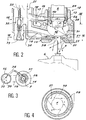
- the sheath 12 which is more visible in FIG. 2, comprises in particular an upper cylindrical part 13 joined to a bottom 14 in the form of a cup and the wall of which is pierced just in front of one of the needles 5.
- the bore is designated by 15.
- the sheath 12 is connected to a hollow piston 16 by an optical fiber duct 17, which extends in the hollow piston 16 then crosses its wall to end in the cylindrical part 13 (the optical fiber is designated by 18), and by an air connection 19 which opens sideways into the bottom 14.
- the air connection 19 communicates inside the hollow piston 16, which can be filled with air by means not shown situated above the holder tool 8.
- the hollow piston 16 still contains an air line 20 and a water line 21 and slides in bearings 22 axially inside the shaft 11 to lower the sleeve 12 from the position shown in the one shown in phantom, where a lower flange 23 erected under the underside of the bottom 14 is placed on the stud 6 around the needle 5 chosen, which enters the bottom 14 through the bore 15.
- the tool holder 8 is itself movable in the sliding direction of the hollow piston 16, and it then drives a nacelle 24 of cylindrical shape and partially contained in the sheath 12, towards the bottom of the latter.
- the tool holder 8, carrying the median shaft 11, and the hollow piston 16 are therefore movable independently in translation, but the median shaft 11 and the hollow piston 16 are integral in rotation due to the engagement of the nacelle 24 in the sheath 12 and the fixing of the nacelle 24 to a plate 25 that the median shaft 11 moves.
- a container R called the jug-cursor by the applicant, retained and placed in the nacelle 24 and whose bottom F protrudes from the latter by a hole 26 which crosses the underside of the nacelle 24, is thus moved and placed above a sampling head 1, chosen as a function of the rotation of the allnant plug 7, then lowered on the needle 5 of the sampling head 1, which finally pierces the bottom F. More precisely, the rotation of the rotating plug 7 brings the container R within reach of a sampling head 1 from each of the crowns, and the choice between these two heads is accomplished by a rotation of the median shaft 11, the axis of which is midway between the two crowns and on which the container R is offset. Air pressure on the top of container R can be added to the weight of container R to force drilling.
- the various moving parts are driven by electric motors or pneumatic means and transmissions which are not shown because they are not the subject of any original detail and are present on the existing and known installation.
- the pipes are connected to fixed pipes for supplying water or air by means of flexible pipes above the tool holder 8 and which are not shown either.
- the water line 21 divides out of the hollow piston 16, inside the bottom 14 of the sleeve 12 or in front of it, to supply spray nozzles placed in the bottom 14 of the sleeve 12 : there are ten in the realization caused here, that is to say three nozzles 27 for spraying the container R, six barrier nozzles 28 and a nozzle 29 for spraying the needle 5.
- the three nozzles 27 for spraying the container open into the hollow 30 delimited by a internal face 31 of the bottom wall 14 and near the bottom of this hollow 30, not far from the bore 15, and they are oriented (see also FIG.
- the internal face 31 is curved and smooth, without abrupt change in slope which would produce recesses in which the droplets would tend to stagnate.
- the six dam nozzles 28 open out at the very top of the hollow 30, almost at the level of the cylindrical part 13 and emit jets at low flow rate and at low pressure, concurrent horizontal jets tangent to the bottom F which finish washing this bottom F, in particular on the cylindrical portion adjacent to its flat end face that the needle 5 pricks.
- the jets from the dam nozzles 28 also have for function of cutting the portions of jets originating from the spray nozzles 27 of the container R which would rise excessively and could project possibly contaminated droplets onto higher parts of the container R.
- the barrier nozzles 28 are located above the nozzles 27 for spraying the container R and their jets can also be oblique laterally to reinforce the vortex on the internal face 31.
- the needle spray nozzle 29 is housed in the flange 23 in the direction of the needle 5 and is used to clean the latter. It is unique but there could be several around the needle 5. As this nozzle 21 is put into service after the others, when the washing water from the hollow 30 and the bottom F has flowed, it requires a network of particular diet, which explains why one may be tempted to omit it from the device. It is moreover not essential and is rather an additional precaution.
- the installation also includes a drying system, clearly visible in Figures 2 and 3, which comprises a suction tube 35 at the bottom of the compressed air line 20 to locally create a narrowing of section and a depression; a pipe 36 opens out at the neck of the suction horn 35 and ends in a groove 37 established behind the top of the internal face 31 and which only four orifices 38 connect to the hollow 30.
- These orifices 38 are therefore suction orifices by which the residual water in the washing is sucked from the internal face 31 and the bottom F of the container R, then ejected through the orifice 39 of the compressed air line 20.
- the suction device by combining a current d air and a static means of creating vacuum is clever because air can be distracted from the air supply almost uncomplicated transport lines for installation.
- the container R can be returned to the network 10 after drying. For this, air is sent to the hollow piston 16 and to the air connection 19.
- the optical fiber 18 makes it possible to verify that a container R is at the bottom of the nacelle 24.
- the nacelle 24 is pierced with a window 40 which normally reveals a portion of a flange C of the container R, located just above the bottom F and whose utility is to guide the container R in the compressed air lines and incidentally to retain the container R in the nacelle 24 by preventing it from falling through the hole 26.
- the flange C can be identified by the optical fiber 18 by virtue of its color or another identifying characteristic.
- FIGS. 2 and 4 The washing illustrated in FIGS. 2 and 4 takes place when the sheath 12 and the basket 24 have been lifted from the piercing needle 5 and have returned to the position of FIG. 1 after filling the container R.
- the drying is done after a return of the sheath 12 on the pad 6, the nacelle 24 remaining raised to spread the bottom F of the needle 5, in order to plug the bore at the bottom of the hollow 30 and allow the container R to be returned to at the top and in the pneumatic transfer network by air supplied by the hollow piston 16.
Landscapes
- Life Sciences & Earth Sciences (AREA)
- Chemical & Material Sciences (AREA)
- Health & Medical Sciences (AREA)
- Physics & Mathematics (AREA)
- Pathology (AREA)
- Analytical Chemistry (AREA)
- Biochemistry (AREA)
- General Health & Medical Sciences (AREA)
- General Physics & Mathematics (AREA)
- Immunology (AREA)
- Engineering & Computer Science (AREA)
- Hydrology & Water Resources (AREA)
- Medicinal Chemistry (AREA)
- Food Science & Technology (AREA)
- General Engineering & Computer Science (AREA)
- High Energy & Nuclear Physics (AREA)
- Automatic Analysis And Handling Materials Therefor (AREA)
- Sampling And Sample Adjustment (AREA)
- Filling Of Jars Or Cans And Processes For Cleaning And Sealing Jars (AREA)
- Basic Packing Technique (AREA)
Abstract
Description
- L'invention concerne un dispositif de remplissage d'un récipient clos par une aiguille, muni de moyens de nettoyage.
- Elle trouve notamment emploi dans une installation d'analyse de liquides dangereux, notamment radioactifs, où les récipients contenant les échantillons de liquide sont transportés par voie pneumatique dans un réseau de conduites entre différentes stations et en particulier des stations d'analyse. Il est cependant nécessaire de remplir au préalable les récipients, et c'est pourquoi une de ces stations du réseau est consacrée au remplissage. Cette station comporte essentiellement au moins un élévateur de liquide de remplissage terminé par une aiguille de perçage du récipient et un fourreau comprenant un fond percé devant l'aiguille. Le récipient à remplir est posé dans une nacelle coulissant dans le fourreau, qui reste suspendue à quelque distance du fond du fourreau pendant la plus grande partie des opérations de remplissage et qui est abaissée au fond du fourreau pour provoquer le perçage du fond du récipient par l'aiguille.
- Les inconvénients qui résultent de cette conception sont liés à la pollution de l'enveloppe du récipient, voire du fond du fourreau. L'élévateur de liquide de remplissage peut en effet être sujet à des défauts de fonctionnement qui se traduisent par de petits jaillissements de liquide qui éclaboussent le récipient et le fond du fourreau, ou de simples suintements qui coulent le long de l'aiguille et se déposent sur le fond du récipient autour du trou de perçage. La grande vitesse (15 mètres à la seconde) acquise par les récipients pendant leur transport dans les canalisations provoque alors généralement une dispersion des gouttelettes dans les conduits et une pollution susceptible de se propager dans tout le réseau à cause notamment des mouvements de l'air de déplacement .
- L'invention est relative à un perfectionnement d'une installation de remplissage existante et a pour objet de nettoyer le fond du récipient et la face interne de la paroi de fond du fourreau pour les débarrasser des liquides polluants qui risquent de les souiller.
- Elle concerne sous sa forme la plus générale un dispositif de remplissage d'un récipient clos, comprenant : un élévateur de liquide de remplissage terminé par une aiguille de perçage d'un fond du récipient ; un fourreau ayant un fond constitué par une paroi percée devant l'aiguille, mobile vers l'aiguille et se raccordant à un réseau de conduits de transport du récipient par voie pneumatique ; et une nacelle située dans le fourreau et agencée pour suspendre le récipient un peu au-dessus du fond du fourreau ; caractérisé en ce que le fourreau est équipé de buses d'aspersion de liquide de lavage vers le fond du récipient suspendu dans la nacelle et vers la face interne de la paroi du fond du fourreau.
- Le liquide polluant est alors amené à ruisseler avec le liquide de lavage et à couler au-dessous du fourreau et de l'aiguille jusque dans un égout où il ne peut plus nuire.
- D'autres moyens peuvent compléter l'invention, tels que des buses supplémentaires d'aspersion du liquide de lavage vers l'aiguille et des moyens de séchage du fond du récipient et de la face interne de la paroi du fond du fourreau. De plus, il est avantageux que les buses soient orientées de façon à asperger le fond du récipient obliquement et à produire un rebondissement du liquide de lavage du fond du récipient vers la face interne du fond du fourreau.
- L'invention va maintenant être décrite à titre illustratif et non limitatif au moyen des figures suivantes :
- la figure 1 est une vue générale du dispositif de remplissage,
- la figure 2 est un détail montrant les parties essentielles,
- la figure 3 est une coupe sur la ligne III-III de la figure 2,
- et la figure 4 est un détail de la figure 3 illustrant le mode de lavage.
- L'installation de remplissage comprend en réalité (figure 1) plusieurs têtes de remplissage 1 disposées suivant deux couronnes concentriques sur un fond de cuve 2 ; chacune des têtes de remplissage 1 est reliée à un réservoir de liquide 3 par un élévateur à bulles 4 qui se termine par une aiguille 5 fixée sur un plot de prélèvement 6. Le fond de cuve 2 est une enceinte très polluée, surmontée d'un couvercle ou bouchon 7 qui l'isole de l'extérieur mais est cependant percé et occupé à l'endroit du perçage par un porte-outil 8. Le bouchon 7 tourne autour d'un axe non représenté qui coïncide avec celui des couronnes de têtes de remplissage 1.
- Ce porte-outil 8 comprend une conduite de raccord 9 à un réseau de conduites de transport par voie pneumatique dont on a représenté une extrémité 10, mobile verticalement jusqu'à s'aboucher à la conduite de raccord 9. Le porte-outil 8 comprend encore un arbre médian 11 tournant autour de son axe pour amener un fourreau 12, situé d'abord sous la conduite de raccord 9 ou au-dessus d'une tête de remplissage 1 d'une des couronnes, au-dessus d'un endroit de l'autre couronne de têtes de remplissage 1 si nécessaire. L'arbre médian 11 traverse le porte-outil 8 de part en part et s'étend au-dessous de lui.
- Le fourreau 12, qui est plus visible à la figure 2, comprend en particulier une partie cylindrique 13 supérieure jointe à un fond 14 en forme de coupelle et dont la paroi est percée juste devant une des aiguilles 5. Le perçage est désigné par 15.
- Le fourreau 12 est relié à un piston creux 16 par un conduit de fibre optique 17, qui s'étend dans le piston creux 16 puis traverse sa paroi pour aboutir dans la partie cylindrique 13 (la fibre optique est désignée par 18), et par un raccordement d'air 19 qui débouche de côté dans le fond 14. Le raccordement d'air 19 communique dans l'intérieur du piston creux 16, qui peut être rempli d'air par des moyens non représentés situés au-dessus du porte-outil 8.
- En référence à la figure 1, le piston creux 16 contient encore une canalisation d'air 20 et une canalisation d'eau 21 et coulisse dans des paliers 22 axialement à l'intérieur de l'arbre 11 pour abaisser le fourreau 12 de la position représentée à celle qui est indiquée en traits mixtes, où une collerette inférieure 23 érigée sous la face inférieure du fond 14 se pose sur le plot 6 autour de l'aiguille 5 choisie, qui entre dans le fond 14 par le perçage 15.
- Le porte-outil 8 est lui-même mobile dans la direction de coulisse du piston creux 16, et il enfonce alors une nacelle 24 de forme cylindrique et partiellement contenue dans le fourreau 12, vers le fond de celui-ci. Le porte-outil 8, porteur de l'arbre médian 11, et le piston creux 16 sont donc mobiles indépendamment en translation, mais l'arbre médian 11 et le piston creux 16 sont solidaires en rotation à cause de l'engagement de la nacelle 24 dans le fourreau 12 et de la fixation de la nacelle 24 à un plateau 25 que l'arbre médian 11 meut. Un récipient R, appelé cruchon-curseur par la déposante, retenu et posé dans la nacelle 24 et dont le fond F dépasse de celle-ci par un trou 26 qui traverse la face inférieure de la nacelle 24, est ainsi déplacé et mis au-dessus d'une tête de prélèvement 1, choisie en fonction de la rotation du bouchon toutnant 7, puis abaissé sur l'aiguille 5 de la tête de prélèvement 1, qui perce finalement le fond F. Plus précisément, la rotation du bouchon tournant 7 amène le récipient R à portée d'une tête de prélèvement 1 de chacune des couronnes, et le choix entre ces deux têtes est accompli par une rotation de l'arbre médian 11, dont l'axe est à mi-distance des deux couronnes et sur lequel le récipient R est excentré. Une pression d'air sur le sommet du récipient R peut s'ajouter au poid du récipient R pour imposer le perçage.
- Les différentes pièces mobiles sont mues par des moteurs électriques ou des moyens pneumatiques et des transmissions qui ne sont pas représentés car ils ne font l'objet d'aucun détail original et sont présents sur l'installation existante et connue. Les canalisations sont raccordées à des canalisations fixes d'alimentation en eau ou en air par l'intermédiaire de tuyaux souples au-dessus du porte-outil 8 et qui ne sont pas non plus représentés.
- En référence à la figure 2, la canalisation d'eau 21 se divise hors du piston creux 16, à l'intérieur du fond 14 du fourreau 12 ou devant lui, pour alimenter des buses d'aspersion placées dans le fond 14 du fourreau 12 : on en compte dix dans la réalisation provoquée ici, soit trois buses 27 d'aspersion du récipient R, six buses de barrage 28 et une buse 29 d'aspersion de l'aiguille 5. Les trois buses 27 d'aspersion du récipient débouchent dans le creux 30 délimité par une face interne 31 de la paroi du fond 14 et près du bas de ce creux 30, non loin du perçage 15, et elles sont orientées (voir aussi la figure 4) suffisamment obliquement pour projeter l'eau vers le fond F du récipient R, et avec une incidence latérale suffisante pour que, quand l'eau a rebondi sur le fond F du récipient R vers la face interne 31, un tourbillon soit produit sur toute la surface de la face interne 31 qui est ainsi complètement arrosée et lavée : les gouttelettes de liquide contaminant originaires de l'aiguille 5 après un jaillissement intempestif éventuel s'écoulent par le perçage 15 et coulent ensuite le long du plot 6 puis dans un égout non représenté situé au-dessous du fond de cuve 2. Cet égout peut être un simple collecteur de ruissellement par gravité, et sa conception ne nécessite pas de finesses particulières car la chambre de remplissage située sous le bouchon tournant 7 peut rester polluée sans inconvénient.
- La face interne 31 est courbe et lisse, sans changement brusque de pente qui produirait des recoins dans lesquels les gouttelettes auraient tendance à stagner.
- Les six buses de barrage 28 débouchent tout au sommet du creux 30, presque à hauteur de la partie cylindrique 13 et émettent des jets à faible débit et à faible pression, jets horizontaux concourants et tangents au fond F qui achèvent de laver ce fond F, en particulier sur la portion cylindrique adjacente à sa face plane d'extrémité que l'aiguille 5 pique. Les jets issus des buses de barrage 28 ont également pour fonction de couper les portions de jets originaires des buses 27 d'aspersion du récipient R qui s'élèveraient exagérément et pourraient projeter des gouttelettes éventuellement contaminées sur des parties plus élevées du récipient R. Les buses de barrage 28 sont situées au-dessus des buses 27 d'aspersion du récipient R et leurs jets peuvent aussi être obliques latéralement pour renforcer le tourbillon sur la face interne 31.
- La buse 29 d'aspersion de l'aiguille est logée dans la collerette 23 en direction de l'aiguille 5 et sert à nettoyer celle-ci. Elle est unique mais on pourrait en disposer plusieurs autour de l'aiguille 5. Comme cette buse 21 est mise en service après les autres, quand l'eau de lavage du creux 30 et du fond F a coulé, elle nécessite un réseau d'alimentation particulier, ce qui explique qu'on puisse être tenté de l'omettre du dispositif. Elle n'est d'ailleurs pas indispensable et relève plutôt d'une précaution supplémentaire.
- L'installation comprend également un système de séchage, bien visible sur les figures 2 et 3, qui comprend une trompe d'aspiration 35 en bas de la canalisation d'air comprimé 20 pour y créer localement un rétrécissement de section et une dépression ; un tuyau 36 débouche au col de la trompe d'aspiration 35 et aboutit dans une gorge 37 établie derrière le sommet de la face interne 31 et que seuls quatre orifices 38 relient au creux 30. Ces orifices 38 sont donc des orifices d'aspiration par lesquels l'eau résiduelle au lavage est aspirée de la face interne 31 et du fond F du récipient R, puis éjectée par l'orifice 39 de la canalisation d'air comprimé 20. Le dispositif d'aspiration par combinaison d'un courant d'air et d'un moyen statique de création de dépression est astucieux car l'air peut être distrait de l'alimentation en air des conduites de transport presque sans complication de l'installation.
- Le récipient R peut être renvoyé dans le réseau 10 après le séchage. On envoie pour cela de l'air dans le piston creux 16 et dans le raccordement d'air 19. La fibre optique 18 permet de vérifier qu'un récipient R est au fond de la nacelle 24.
- La nacelle 24 est percée d'une fenêtre 40 qui dévoile normalement une portion d'une collerette C du récipient R, située juste au-dessus du fond F et dont l'utilité est de guider le récipient R dans les conduites d'air comprimé et accessoirement de retenir le récipient R dans la nacelle 24 en l'empêchant de tomber par le trou 26. La collerette C est repérable par la fibre optique 18 grâce à sa couleur ou à une autre caractéristique d'identification.
- Le lavage illustré sur les figures 2 et 4 se déroule quand le fourreau 12 et la nacelle 24 ont été relevés de l'aiguille 5 de perçage et sont revenus à la position de la figure 1 après le remplissage du récipient R.
- Le séchage est fait après un retour du fourreau 12 sur le plot 6, la nacelle 24 restant soulevée pour écarter le fond F de l'aiguille 5, afin de boucher le perçage au bas du creux 30 et de permettre de renvoyer le récipient R vers le haut et dans le réseau de transfert pneumatique par de l'air fourni par le piston creux 16.
Claims (7)
- Dispositif de remplissage d'un récipient clos (R), comprenant : un élévateur de liquide (4) de remplissage terminé par une aiguille (5) de perçage d'un fond (F) du récipient ; un fourreau (12) ayant un fond (14) constitué par une paroi percée (15) devant l'aiguille (5), mobile vers l'aiguille et se raccordant à un réseau de conduits (9, 10) de transport du récipient par voie pneumatique ; et une nacelle (24) située dans le fourreau et agencée pour suspendre le récipient (R) un peu au-dessus du fond (14) du fourreau ; caractérisé en ce que le fourreau (12) est équipé de buses (27, 28) d'aspersion de liquide de lavage vers le fond (F) du récipient suspendu dans la nacelle et vers la face interne (31) de la paroi du fond du fourreau.
- Dispositif de remplissage suivant la revendication 1, caractérisé en ce que certaines des buses (27) sont orientées de façon à asperger le fond du récipient obliquement et à produire un rebondissement du liquide de lavage du fond du récipient vers la face interne du fond du fourreau.
- Dispositif de remplissage suivant la revendications 2, caractérisé en ce que certaines des buses (28) sont orientées tangentiellement au fond du récipient, à hauteur du fond (F) du récipient et d'une portion adjacente du récipient.
- Dispositif de remplissage suivant l'une quelconque des revendications 1 à 3, caractérisé en ce que certaines des buses (27, 28) sont orientées de façon à asperger la face interne (31) du fond du fourreau obliquement et à y produire un tourbillon du liquide de lavage.
- Dispositif de remplissage suivant l'une quelconque des revendications 1 à 4, caractérisé en ce que le fourreau est équipé d'au moins une buse (29) d'aspersion de liquide vers l'aiguille.
- Dispositif de remplissage suivant l'une quelconque des revendications 1 à 5, caractérisé en ce que le fourreau est équipé de moyens de séchage (35 à 38) du fond (F) du récipient (R) et de la face interne (31) de la paroi du fond (14) du fourreau (12).
- Dispositif de remplissage suivant la revendication 6, caractérisé en ce que les moyens de séchage consistent en des moyens d'aspiration animés par un circuit d'air comprimé (20) muni d'un moyen statique de création de dépression (35).
Applications Claiming Priority (2)
| Application Number | Priority Date | Filing Date | Title |
|---|---|---|---|
| FR9309661A FR2708743B1 (fr) | 1993-08-05 | 1993-08-05 | Dispositif de remplissage d'un récipient clos par une aiguille, muni de moyens de nettoyage. |
| FR9309661 | 1993-08-05 |
Publications (2)
| Publication Number | Publication Date |
|---|---|
| EP0637740A1 true EP0637740A1 (fr) | 1995-02-08 |
| EP0637740B1 EP0637740B1 (fr) | 1999-03-03 |
Family
ID=9449978
Family Applications (1)
| Application Number | Title | Priority Date | Filing Date |
|---|---|---|---|
| EP94401796A Expired - Lifetime EP0637740B1 (fr) | 1993-08-05 | 1994-08-03 | Dispositif de remplissage d'un récipient clos par une aiguille, muni de moyens de nettoyage |
Country Status (7)
| Country | Link |
|---|---|
| US (1) | US5518049A (fr) |
| EP (1) | EP0637740B1 (fr) |
| JP (1) | JP3340247B2 (fr) |
| KR (1) | KR100306017B1 (fr) |
| CA (1) | CA2129486A1 (fr) |
| DE (1) | DE69416745T2 (fr) |
| FR (1) | FR2708743B1 (fr) |
Cited By (1)
| Publication number | Priority date | Publication date | Assignee | Title |
|---|---|---|---|---|
| CN114796680A (zh) * | 2022-04-26 | 2022-07-29 | 郑州大学第一附属医院 | 一种产后清洁及护理装置 |
Families Citing this family (2)
| Publication number | Priority date | Publication date | Assignee | Title |
|---|---|---|---|---|
| US5602349A (en) * | 1994-10-14 | 1997-02-11 | The University Of Washington | Sample introduction system for a flow cytometer |
| DE10358265A1 (de) * | 2003-12-11 | 2005-07-28 | Pöpplau, Jens H., Dr.-Ing. | Behälterbehandlungsvorrichtung mit Gasvorhang |
Citations (6)
| Publication number | Priority date | Publication date | Assignee | Title |
|---|---|---|---|---|
| DE3044424A1 (de) * | 1980-11-26 | 1982-06-24 | Kernforschungszentrum Karlsruhe Gmbh, 7500 Karlsruhe | Einrichtung zum abfuellen einer radioaktiven oder toxischen probe |
| EP0063971A1 (fr) * | 1981-04-08 | 1982-11-03 | Commissariat à l'Energie Atomique | Dispositif de prélèvement d'échantillons liquides |
| EP0078212A1 (fr) * | 1981-10-26 | 1983-05-04 | Commissariat à l'Energie Atomique | Banc de prélèvement d'échantillons liquides |
| EP0472831A1 (fr) * | 1990-07-27 | 1992-03-04 | Deutsche Gesellschaft für Wiederaufarbeitung von Kernbrennstoffen mbH | Appareil d'échantillonnage des gaz et/ou des liquides de l'enceinte de confinement d'une centrale nucléaire |
| EP0511097A1 (fr) * | 1991-04-23 | 1992-10-28 | Compagnie Generale Des Matieres Nucleaires (Cogema) | Installation de prélèvement d'échantillons fluides dans une zone confinée |
| EP0522959A1 (fr) * | 1991-07-10 | 1993-01-13 | Cogema Compagnie Generale Des Matieres Nucleaires | Procédé et installation pour transférer en dehors d'une enceinte étanche un fluide contenu dans un récipient fermé |
Family Cites Families (11)
| Publication number | Priority date | Publication date | Assignee | Title |
|---|---|---|---|---|
| FR999155A (fr) * | 1952-01-25 | |||
| US2519353A (en) * | 1946-10-15 | 1950-08-22 | American Can Co | Can closing machine |
| DE926350C (de) * | 1953-01-01 | 1955-04-14 | Seitz Werke Gmbh | Einrichtung an Flaschenfuellmaschinen |
| US2787875A (en) * | 1954-04-16 | 1957-04-09 | Aseptic Food Fillers Inc | Filling head |
| NL233234A (fr) * | 1957-11-14 | |||
| CH546603A (de) * | 1972-06-14 | 1974-03-15 | Greiner Electronic Ag | Verfahren zur reinigung der innen- und/oder aussenseite eines gefaesses und einrichtung zur durchfuehrung des verfahrens. |
| DE2739742C3 (de) * | 1977-09-03 | 1981-02-12 | Hermann 8404 Woerth Kronseder | Gefäßfüllvorrichtung |
| US4417607A (en) * | 1981-06-29 | 1983-11-29 | Scholle Corporation | Apparatus and method for aseptically filling flexible containers |
| US4498508A (en) * | 1983-02-04 | 1985-02-12 | Scholle Corporation | Container filler |
| US4615360A (en) * | 1985-09-05 | 1986-10-07 | Eastman Kodak Company | Means providing separation of exterior sheath of liquid on dispensing tip |
| SE461032B (sv) * | 1988-03-21 | 1989-12-18 | Roby Teknik Ab | Anordning vid en foerpackningsmaskin foer att ombesoerja en steril fyllningsatmosfaer |
-
1993
- 1993-08-05 FR FR9309661A patent/FR2708743B1/fr not_active Expired - Fee Related
-
1994
- 1994-07-29 KR KR1019940018689A patent/KR100306017B1/ko not_active Expired - Fee Related
- 1994-08-02 US US08/284,125 patent/US5518049A/en not_active Expired - Lifetime
- 1994-08-03 DE DE69416745T patent/DE69416745T2/de not_active Expired - Fee Related
- 1994-08-03 EP EP94401796A patent/EP0637740B1/fr not_active Expired - Lifetime
- 1994-08-04 JP JP18318194A patent/JP3340247B2/ja not_active Expired - Fee Related
- 1994-08-04 CA CA002129486A patent/CA2129486A1/fr not_active Abandoned
Patent Citations (6)
| Publication number | Priority date | Publication date | Assignee | Title |
|---|---|---|---|---|
| DE3044424A1 (de) * | 1980-11-26 | 1982-06-24 | Kernforschungszentrum Karlsruhe Gmbh, 7500 Karlsruhe | Einrichtung zum abfuellen einer radioaktiven oder toxischen probe |
| EP0063971A1 (fr) * | 1981-04-08 | 1982-11-03 | Commissariat à l'Energie Atomique | Dispositif de prélèvement d'échantillons liquides |
| EP0078212A1 (fr) * | 1981-10-26 | 1983-05-04 | Commissariat à l'Energie Atomique | Banc de prélèvement d'échantillons liquides |
| EP0472831A1 (fr) * | 1990-07-27 | 1992-03-04 | Deutsche Gesellschaft für Wiederaufarbeitung von Kernbrennstoffen mbH | Appareil d'échantillonnage des gaz et/ou des liquides de l'enceinte de confinement d'une centrale nucléaire |
| EP0511097A1 (fr) * | 1991-04-23 | 1992-10-28 | Compagnie Generale Des Matieres Nucleaires (Cogema) | Installation de prélèvement d'échantillons fluides dans une zone confinée |
| EP0522959A1 (fr) * | 1991-07-10 | 1993-01-13 | Cogema Compagnie Generale Des Matieres Nucleaires | Procédé et installation pour transférer en dehors d'une enceinte étanche un fluide contenu dans un récipient fermé |
Cited By (2)
| Publication number | Priority date | Publication date | Assignee | Title |
|---|---|---|---|---|
| CN114796680A (zh) * | 2022-04-26 | 2022-07-29 | 郑州大学第一附属医院 | 一种产后清洁及护理装置 |
| CN114796680B (zh) * | 2022-04-26 | 2023-05-26 | 郑州大学第一附属医院 | 一种产后清洁及护理装置 |
Also Published As
| Publication number | Publication date |
|---|---|
| FR2708743B1 (fr) | 1995-09-22 |
| JP3340247B2 (ja) | 2002-11-05 |
| CA2129486A1 (fr) | 1995-02-06 |
| DE69416745T2 (de) | 1999-09-02 |
| FR2708743A1 (fr) | 1995-02-10 |
| DE69416745D1 (de) | 1999-04-08 |
| KR100306017B1 (ko) | 2001-12-15 |
| US5518049A (en) | 1996-05-21 |
| EP0637740B1 (fr) | 1999-03-03 |
| JPH07198724A (ja) | 1995-08-01 |
| KR950006445A (ko) | 1995-03-21 |
Similar Documents
| Publication | Publication Date | Title |
|---|---|---|
| EP0477341B2 (fr) | Dispositifs et machine de traitement de bouteilles | |
| EP0417009A1 (fr) | Appareil et installation pour le nettoyage de drains, notamment dans un puits de production pétrolière | |
| FR2550996A1 (fr) | Recipient d'encre et dispositif recuperateur d'encre, notamment pour imprimante | |
| EP0597161B1 (fr) | Dispositif mixte de soutirage d'un liquide et dispositif de nettoyage associe | |
| FR2648125A1 (fr) | Machine de bouchage de bouteilles, de type rotatif, a dispositif fixe de lavage de ses organes de bouchage | |
| EP0637740B1 (fr) | Dispositif de remplissage d'un récipient clos par une aiguille, muni de moyens de nettoyage | |
| EP0268524B1 (fr) | Tête de remplissage pour machine de remplissage de bouteilles et machine de remplissage équipée de telles têtes de remplissage | |
| EP0162769A1 (fr) | Dispositif de nettoyage du sol, notamment pour le prélèvement des déjections canines | |
| EP1002494B1 (fr) | Distributeur de produits pour lave-vaisselle | |
| FR2493291A1 (fr) | Dispositif de remplissage automatique de bouteilles et installation en comportant application | |
| FR3104550A1 (fr) | Poste de remplissage pour installation de conditionnement comprenant un bec de remplissage à canal d’aspiration intégré | |
| FR2792620A1 (fr) | Support de poche souple et distributeur comprenant un tel support | |
| FR2547388A1 (fr) | Obturateur a flotteur pour sortie de cuve d'aspirateur electrique | |
| EP1893123A1 (fr) | Procede pour conditionner dans une paillette une dose predeterminee de substance liquide et dispositif pour le mettre en oeuvre | |
| EP0214903A1 (fr) | Perfectionnement aux dispositifs de prélèvement automatique d'échantillons | |
| EP1615014B1 (fr) | Dispositif de prélèvement d'échantillon liquide dans un circuit de pompage et procédé de nettoyage de ce dispositif | |
| EP1082265A1 (fr) | Bec de remplissage | |
| FR2525582A1 (fr) | Installation de soutirage | |
| FR2574659A1 (fr) | Chaine de fabrication pour des medicaments homeopathiques, notamment pour l'impregnation des granules ou globules | |
| EP0906889B1 (fr) | Dispositif d'emplissage de bouteilles avec mise à niveau du liquide dans lesdites bouteilles, sans perte de liquide | |
| FR2559050A1 (fr) | Equipement perfectionne pour le nettoyage profond de surfaces textiles, tapis, moquettes ou similaires | |
| FR2629572A1 (fr) | Dispositif pour l'essorage de produits divers, et plus particulierement de bouteilles de gaz | |
| FR2611688A1 (fr) | Dispositif de drainage des egouttements pour pistolets de distribution des carburants et autres produits liquides | |
| FR2547644A1 (fr) | Dispositif de lubrification d'air comprime | |
| FR2637885A1 (fr) | Machine de remplissage de recipients tels que des bouteilles par gravite |
Legal Events
| Date | Code | Title | Description |
|---|---|---|---|
| PUAI | Public reference made under article 153(3) epc to a published international application that has entered the european phase |
Free format text: ORIGINAL CODE: 0009012 |
|
| AK | Designated contracting states |
Kind code of ref document: A1 Designated state(s): BE CH DE ES GB IT LI NL SE |
|
| 17P | Request for examination filed |
Effective date: 19950713 |
|
| GRAG | Despatch of communication of intention to grant |
Free format text: ORIGINAL CODE: EPIDOS AGRA |
|
| 17Q | First examination report despatched |
Effective date: 19980529 |
|
| GRAG | Despatch of communication of intention to grant |
Free format text: ORIGINAL CODE: EPIDOS AGRA |
|
| GRAH | Despatch of communication of intention to grant a patent |
Free format text: ORIGINAL CODE: EPIDOS IGRA |
|
| GRAH | Despatch of communication of intention to grant a patent |
Free format text: ORIGINAL CODE: EPIDOS IGRA |
|
| GRAA | (expected) grant |
Free format text: ORIGINAL CODE: 0009210 |
|
| AK | Designated contracting states |
Kind code of ref document: B1 Designated state(s): BE CH DE ES GB IT LI NL SE |
|
| PG25 | Lapsed in a contracting state [announced via postgrant information from national office to epo] |
Ref country code: SE Free format text: THE PATENT HAS BEEN ANNULLED BY A DECISION OF A NATIONAL AUTHORITY Effective date: 19990303 Ref country code: ES Free format text: THE PATENT HAS BEEN ANNULLED BY A DECISION OF A NATIONAL AUTHORITY Effective date: 19990303 |
|
| REG | Reference to a national code |
Ref country code: CH Ref legal event code: EP |
|
| REF | Corresponds to: |
Ref document number: 69416745 Country of ref document: DE Date of ref document: 19990408 |
|
| ITF | It: translation for a ep patent filed | ||
| GBT | Gb: translation of ep patent filed (gb section 77(6)(a)/1977) |
Effective date: 19990506 |
|
| PLBE | No opposition filed within time limit |
Free format text: ORIGINAL CODE: 0009261 |
|
| STAA | Information on the status of an ep patent application or granted ep patent |
Free format text: STATUS: NO OPPOSITION FILED WITHIN TIME LIMIT |
|
| 26N | No opposition filed | ||
| PG25 | Lapsed in a contracting state [announced via postgrant information from national office to epo] |
Ref country code: NL Free format text: LAPSE BECAUSE OF NON-PAYMENT OF DUE FEES Effective date: 20000301 |
|
| NLV4 | Nl: lapsed or anulled due to non-payment of the annual fee |
Effective date: 20000301 |
|
| PGFP | Annual fee paid to national office [announced via postgrant information from national office to epo] |
Ref country code: CH Payment date: 20010817 Year of fee payment: 8 |
|
| PGFP | Annual fee paid to national office [announced via postgrant information from national office to epo] |
Ref country code: BE Payment date: 20010927 Year of fee payment: 8 |
|
| REG | Reference to a national code |
Ref country code: GB Ref legal event code: IF02 |
|
| PG25 | Lapsed in a contracting state [announced via postgrant information from national office to epo] |
Ref country code: LI Free format text: LAPSE BECAUSE OF NON-PAYMENT OF DUE FEES Effective date: 20020831 Ref country code: CH Free format text: LAPSE BECAUSE OF NON-PAYMENT OF DUE FEES Effective date: 20020831 Ref country code: BE Free format text: LAPSE BECAUSE OF NON-PAYMENT OF DUE FEES Effective date: 20020831 |
|
| BERE | Be: lapsed |
Owner name: CIE GENERALE DES MATIERES NUCLEAIRES *COGEMA Effective date: 20020831 |
|
| REG | Reference to a national code |
Ref country code: CH Ref legal event code: PL |
|
| PGFP | Annual fee paid to national office [announced via postgrant information from national office to epo] |
Ref country code: DE Payment date: 20040823 Year of fee payment: 11 |
|
| PG25 | Lapsed in a contracting state [announced via postgrant information from national office to epo] |
Ref country code: IT Free format text: LAPSE BECAUSE OF NON-PAYMENT OF DUE FEES;WARNING: LAPSES OF ITALIAN PATENTS WITH EFFECTIVE DATE BEFORE 2007 MAY HAVE OCCURRED AT ANY TIME BEFORE 2007. THE CORRECT EFFECTIVE DATE MAY BE DIFFERENT FROM THE ONE RECORDED. Effective date: 20050803 |
|
| PG25 | Lapsed in a contracting state [announced via postgrant information from national office to epo] |
Ref country code: DE Free format text: LAPSE BECAUSE OF NON-PAYMENT OF DUE FEES Effective date: 20060301 |
|
| PGFP | Annual fee paid to national office [announced via postgrant information from national office to epo] |
Ref country code: GB Payment date: 20120824 Year of fee payment: 19 |
|
| GBPC | Gb: european patent ceased through non-payment of renewal fee |
Effective date: 20130803 |
|
| PG25 | Lapsed in a contracting state [announced via postgrant information from national office to epo] |
Ref country code: GB Free format text: LAPSE BECAUSE OF NON-PAYMENT OF DUE FEES Effective date: 20130803 |