EP0637749B1 - Système d'analyse des échantillons liquides - Google Patents
Système d'analyse des échantillons liquides Download PDFInfo
- Publication number
- EP0637749B1 EP0637749B1 EP94111934A EP94111934A EP0637749B1 EP 0637749 B1 EP0637749 B1 EP 0637749B1 EP 94111934 A EP94111934 A EP 94111934A EP 94111934 A EP94111934 A EP 94111934A EP 0637749 B1 EP0637749 B1 EP 0637749B1
- Authority
- EP
- European Patent Office
- Prior art keywords
- test
- foil
- storage container
- test elements
- elements
- Prior art date
- Legal status (The legal status is an assumption and is not a legal conclusion. Google has not performed a legal analysis and makes no representation as to the accuracy of the status listed.)
- Expired - Lifetime
Links
Images


Classifications
-
- G—PHYSICS
- G01—MEASURING; TESTING
- G01N—INVESTIGATING OR ANALYSING MATERIALS BY DETERMINING THEIR CHEMICAL OR PHYSICAL PROPERTIES
- G01N33/00—Investigating or analysing materials by specific methods not covered by groups G01N1/00 - G01N31/00
- G01N33/48—Biological material, e.g. blood, urine; Haemocytometers
- G01N33/483—Physical analysis of biological material
- G01N33/487—Physical analysis of biological material of liquid biological material
- G01N33/4875—Details of handling test elements, e.g. dispensing or storage, not specific to a particular test method
- G01N33/48764—Test tape taken off a spool
-
- G—PHYSICS
- G01—MEASURING; TESTING
- G01N—INVESTIGATING OR ANALYSING MATERIALS BY DETERMINING THEIR CHEMICAL OR PHYSICAL PROPERTIES
- G01N21/00—Investigating or analysing materials by the use of optical means, i.e. using sub-millimetre waves, infrared, visible or ultraviolet light
- G01N21/17—Systems in which incident light is modified in accordance with the properties of the material investigated
- G01N21/25—Colour; Spectral properties, i.e. comparison of effect of material on the light at two or more different wavelengths or wavelength bands
- G01N21/251—Colorimeters; Construction thereof
- G01N21/253—Colorimeters; Construction thereof for batch operation, i.e. multisample apparatus
-
- G—PHYSICS
- G01—MEASURING; TESTING
- G01N—INVESTIGATING OR ANALYSING MATERIALS BY DETERMINING THEIR CHEMICAL OR PHYSICAL PROPERTIES
- G01N35/00—Automatic analysis not limited to methods or materials provided for in any single one of groups G01N1/00 - G01N33/00; Handling materials therefor
- G01N35/00029—Automatic analysis not limited to methods or materials provided for in any single one of groups G01N1/00 - G01N33/00; Handling materials therefor provided with flat sample substrates, e.g. slides
-
- G—PHYSICS
- G01—MEASURING; TESTING
- G01N—INVESTIGATING OR ANALYSING MATERIALS BY DETERMINING THEIR CHEMICAL OR PHYSICAL PROPERTIES
- G01N35/00—Automatic analysis not limited to methods or materials provided for in any single one of groups G01N1/00 - G01N33/00; Handling materials therefor
- G01N35/00029—Automatic analysis not limited to methods or materials provided for in any single one of groups G01N1/00 - G01N33/00; Handling materials therefor provided with flat sample substrates, e.g. slides
- G01N2035/00089—Magazines
-
- G—PHYSICS
- G01—MEASURING; TESTING
- G01N—INVESTIGATING OR ANALYSING MATERIALS BY DETERMINING THEIR CHEMICAL OR PHYSICAL PROPERTIES
- G01N35/00—Automatic analysis not limited to methods or materials provided for in any single one of groups G01N1/00 - G01N33/00; Handling materials therefor
- G01N35/00029—Automatic analysis not limited to methods or materials provided for in any single one of groups G01N1/00 - G01N33/00; Handling materials therefor provided with flat sample substrates, e.g. slides
- G01N2035/00099—Characterised by type of test elements
- G01N2035/00108—Test strips, e.g. paper
-
- Y—GENERAL TAGGING OF NEW TECHNOLOGICAL DEVELOPMENTS; GENERAL TAGGING OF CROSS-SECTIONAL TECHNOLOGIES SPANNING OVER SEVERAL SECTIONS OF THE IPC; TECHNICAL SUBJECTS COVERED BY FORMER USPC CROSS-REFERENCE ART COLLECTIONS [XRACs] AND DIGESTS
- Y10—TECHNICAL SUBJECTS COVERED BY FORMER USPC
- Y10T—TECHNICAL SUBJECTS COVERED BY FORMER US CLASSIFICATION
- Y10T436/00—Chemistry: analytical and immunological testing
- Y10T436/11—Automated chemical analysis
- Y10T436/110833—Utilizing a moving indicator strip or tape
-
- Y—GENERAL TAGGING OF NEW TECHNOLOGICAL DEVELOPMENTS; GENERAL TAGGING OF CROSS-SECTIONAL TECHNOLOGIES SPANNING OVER SEVERAL SECTIONS OF THE IPC; TECHNICAL SUBJECTS COVERED BY FORMER USPC CROSS-REFERENCE ART COLLECTIONS [XRACs] AND DIGESTS
- Y10—TECHNICAL SUBJECTS COVERED BY FORMER USPC
- Y10T—TECHNICAL SUBJECTS COVERED BY FORMER US CLASSIFICATION
- Y10T436/00—Chemistry: analytical and immunological testing
- Y10T436/11—Automated chemical analysis
- Y10T436/112499—Automated chemical analysis with sample on test slide
Definitions
- the present invention relates to a system for analysis of sample liquids with the elements using a measuring device Radiation source, radiation receiver, evaluation and display device, a storage container to hold Test elements in which the test elements are arranged spirally and are individually sealed
- the invention further relates to a method of analysis of sample liquids and an arrangement of test elements, where the test elements are connected by a tape are.
- the invention is in the field of analysis of sample liquids without reagent liquids, such as those used for Use body fluid analysis.
- sample liquids without reagent liquids, such as those used for Use body fluid analysis.
- EP-A 0 373 629 and EP-A 0 373 413 describe apparatuses which is a storage container for elements for sample loading have multiple successive determinations of test substances.
- the elements for sample loading have a membrane for separating cells and Particles from blood serum. In the one that passes through the membrane Blood serum is measured using an electronic sensor determines the concentration of an ingredient.
- the variant is rotated to the elements one after the other at the intended Move location to sample.
- a second Embodiment are stacked Strips, each with a membrane for sample application carry, in a storage vessel from which they are brought to the site Sample application can be transported.
- a third Variant are membranes for sample application a filmstrip that is comparable to a photographic Film is rolled up in a cylindrical storage container.
- the elements have Sample application no reagents that the concentration of a Convert the ingredient of the sample liquid into a signal, therefore sensors are necessary that directly Detect determining ingredient.
- the described prior art thus has the disadvantage that sensors directly with the blood serum that passes through the Membrane passes through, are brought into contact. This can lead to contamination of the sensor Can result in falsification of the measurement result and beyond that brings hygienic problems if for example, viruses can pass through said membranes can. For hygiene reasons it is described in the Prior art also disadvantageous that used Elements for sample application remain in the system.
- test strips are fed into the system individually and inside of the system by irradiation with a light source and detection of reflected radiation evaluated.
- a storage system for a large number of test elements is from the US patent 4,218,421 known.
- the test fields are arranged on a tape that is on a first Cylinder is wound up and is unwound to make test fields available.
- Used test elements are wound up on a second roll, the one with the first roll is housed in a housing.
- a protection of as yet unused test elements is used reached this storage container through the housing, which has a closure.
- Japanese patent application 63259469 is a packaging for analytical Test elements are described in which they are individually sealed between two foils. The arrangement between two rollers is used to remove test elements passed, whereby the test elements are pressed out.
- a packaging system for strip-shaped test elements is from US Patent 3,918,910 known.
- FIGS. 24, 25 and 26 there is a seal between the test elements between two Slides shown. To remove a test element, the foils are pulled apart, so that the test elements are released.
- the invention was based on the object of a system available for analysis of sample liquids place, where there are several test elements to carry out of analysis so that they are in sequence can be used without a for each determination refilling from the outside would be necessary.
- the above tasks were carried out by a System for analyzing sample liquids according to claim 1 solved.
- the invention also includes a storage container, and a method for analyzing sample liquids.
- the test elements of the system according to the invention are located yourself in a device that is easy to carry out Analyzes allowed.
- This device has devices with those test elements from the storage container to one place be transported to the sample.
- This or more Devices can also serve to test elements to transport a location for measurement.
- In a preferred one Embodiment of the system fall place of the sample application and location of the measurement together what the handling of the Systems facilitated because there is no additional transport process necessary is.
- With named transport devices can also the ejection of a used test element from the System, but also additional devices can be installed.
- the test elements are transported from a storage container out with the help of a tape on which the test elements are lined up.
- the onward transport of the Test elements in the sample application or measuring position is carried out with the help of a slider that is also rigid with the optics connected is.
- the test elements are in one before they are used Storage container.
- the present invention also relates Storage vessels for use in an inventive System, the spirally arranged test elements contains.
- This storage container preferably has the shape a 3 to 20 mm high box.
- the footprint of this Box can be essentially square or round or be rounded.
- the arrangement of the test elements can through a spiral passage inside the storage container get supported.
- the test elements can transported out of the system through a side opening become.
- test elements in the Storage container can be a variety of test items be arranged to save space. It is this way also a successive removal of test elements possible, in which the test elements in a predetermined Orientation can be taken from the system. A snag the test elements is also by this arrangement prevented.
- the storage container can be made of materials that can be brought into the necessary form and one have sufficient mechanical stability.
- materials include cardboard, metals, such as aluminum, tinplate, brass, etc., and preferred Plastics such as B. polyethylene, polypropylene, polymethyl methacrylate and polystyrene.
- a storage container preferably carries a code strip on which Lot-specific information in device-readable form stand. Magnetic codes, barcodes or come for this machine-readable plain text in question. When inserting the Storage container in the corresponding subject or Drawer of the measuring device, the code is on the magazine automatically by a reading device in the device read.
- Test elements according to the invention have a translucent, essentially cylindrical, plastic pin on, which has a diameter of about 2 to 6 mm and a length from about 2 to 15 mm.
- the plastic pen is from one Surround the jacket so that the end faces are essentially free stay. Suitable as a material for the transparent pen any material that is permeable to light. Optically clear plastics have proven particularly useful. Prefers are polymethyl methacrylate and polycarbonate. On the corresponding test element is the subject of the German one Patent application with the file number P 4227678.0 or the European patent application EP-A-0 585 744.
- the coat that surrounds the translucent pen can also be a plastic, for example polyethylene, Polypropylene or polyvinylidene fluoride.
- a plastic for example polyethylene, Polypropylene or polyvinylidene fluoride.
- Possible combinations for pin / sheath are polycarbonate / polyethylene and Polymethyl methacrylate / polyvinylidene fluoride.
- the translucent Pen can also be made from a vapor-deposited metal coating, for example made of aluminum.
- the Metal coating can in turn be covered with a plastic sheath be enveloped.
- the jacket encloses the plastic pin preferably gas and liquid tight. Preferably protrudes the jacket on the end faces of the plastic pin over this one.
- Reagent layer applied by reaction with a determining analytes generates an optically detectable signal.
- Additional layers can be applied to the reagent layer be, for example, the separation of cells enable.
- the composition of the reagent and auxiliary layers can be state of the art for test strips be removed.
- Test element for an essentially waterproof Foil e.g. B. an aluminum foil or an aluminum laminate
- This can e.g. B. by melting or stick on.
- This embodiment offers the advantage that the reagent is water vapor tight the environment is complete, which is the durability of each Test element guaranteed for weeks. Will the seal of a test element removed, the seal remains the remaining test elements are intact. That kind of seal is called individual sealing.
- the sealing can be done in such a way that the sealed Test elements are available individually. However, two are preferred or several test elements in different locations of the waterproof film sealed, so that the test elements are mechanically connected. Has it Foil in the form of a tape, so the test elements can with this tape are wound spirally. The transport the test elements can also be done through this tape.
- the tape with the sealed individual tests is preferred inserted spirally in a magazine.
- the orientation is preferably chosen so that the tape is on the outside of the spiral.
- a lead of the tape on which the test elements are located is attached to a winding core.
- This winding core is by a mechanism, e.g. B. a gear rotated. Thereby the tape and with it the test elements from the Magazine pulled.
- test element When pulling out a test element, this is done by pulling it off of the tape unsealed. This is preferably done by the direction of movement of the belt by a deflection device will be changed.
- One way is to have a role or edge at the outlet opening of the storage container position over which the tape runs.
- test element An unsealed test element is placed in a sample application position brought.
- the test element is preferred at Transport to the sample application position in a seal pushed, which includes the jacket of the test element. On this can prevent sample liquid from entering the inside of the device can be prevented. It is also advantageous if the frame that the test element during the sample application, in the empty state by a Flap against the ingress of dust, splash water, etc. is protected. Such a flap can Insertion of the test element.
- the measurement of a signal necessary for the concentration to determining ingredient is characteristic of the face of the test element facing away from the reagent.
- the radiation and readout are preferably carried out in each case almost perpendicular to the lower face of the translucent Pin.
- Crosstalk from sender to receiver can be reduced by an intermediate aperture.
- This arrangement combines the possibilities of small size and relatively large distance tolerance.
- a transmitter for Use emitted in a system according to the invention electromagnetic radiation preferred in the optical part of the spectrum. Because of their small size and power consumption have light emitting semiconductor diodes for this purpose has proven itself.
- Preferred reflectance measurements are advantageously semiconductor diodes used in the red and infrared range.
- the receiver receives radiation from that of the transmitter and the receiver-facing side of the reagent layer are emitted becomes.
- those received by the recipient correspond Radiation frequencies essentially those from the transmitter be emitted.
- Radiation frequencies essentially those from the transmitter be emitted.
- from Transmitter emitted and received by the receiver differ in their frequency range if for example Fluorescence processes take place in the reagent layer.
- Receivers are preferably semiconductor devices, such as photodiodes or photo transistors, but they can also by other receivers known in the prior art for electromagnetic radiation.
- the invention also includes a method for analysis of sample liquids with a system with an arrangement of test elements connected by a tape and are in a storage container, including the steps: transport of a test element by means of the tape from the storage container, opening the Sealing of the test element by pulling off the tape from the test element so that a test field of the test element becomes accessible, application of a sample liquid to the Test element, implementation of the measurement process under radiation of the test element and measurement of reflected or transmitted radiation, calculation of an analysis result from the measurement, ejection of the test element used out of the system.
- the transport of a test element from the storage container to the site for sample loading can be done by one Mechanics an unused test element on the belt that the Test elements connects, is pulled out and it follows is pushed to the place for sample application.
- the Pulling out takes place, for example, by the winding core of the storage container is rotated or by the Tape that connects the test elements is pulled.
- Prefers becomes a tape in the form of a film that holds the test elements seals over an edge or roll with small Diameter pulled that the film from the test element is detached and this for applying the sample liquid ready.
- the transport of a test element to the place for sample application is preferred mechanically. This transport process can as well Removal process from the storage container with the opening the sealing of the test element.
- the sample liquid is applied to the test element usually manually, with the test element being preferred located at an exposed point in the system so contamination of the system is largely prevented.
- the location of the sample application and the location for measurement can be different in a system according to the invention, so that transport of the test element is necessary.
- the transport of the sample liquid Test element to the location for measurement is preferred mechanically.
- the measurement can be carried out, for example, by the sample application be started by with the device switched on measurements are carried out at intervals, which make detection of the sample application possible.
- the Measurement of the radiation remitted by the reagent layer is preferably done after a period of time has elapsed, which depend on the test elements used and of the analysis to be performed. It can also take measurements take place at intervals and the temporal change of the measurement signal can be saved. With one Process can both be the optimal time for the calculation the analysis result as well as the kinetics of the detection reaction be determined.
- the calculation of the analysis result from the measurement can with data processing methods known in the prior art respectively. Allocations that determine a Allow concentration from the measurement signal can System saved. Data is preferably located before doing a calibration of the measurement for that in the storage container enable contained test elements. These dates can in the variants already described on the storage container be saved or available separately. Linking of data is particularly preferred test elements used and of permanent in the system stored data for an evaluation of the measurement.
- the determined analysis result can the user on a the displays known in the prior art become. It is also possible to have previous analysis results with associated data, e.g. B. the date, so that the user recognize a change in the analysis results can. This is particularly true in the area of glucose determination beneficial because the patient is in this way Can monitor glucose levels.
- the ejection can be done manually or preferably done mechanically, e.g. B. by the test element with a slider that transports it to the site for measurement has moved over a mechanical resistance becomes.
- a system according to the invention offers the user some Advantages over conventional systems.
- a storage container with a measuring device a large number of analyzes can be carried out without a supply of individual test elements from the outside is necessary is.
- the handling of a system according to the invention is also simplified by the fact that the transport and positioning of the test elements by devices of the system can be specified so that operating errors on a Minimum be reduced.
- An ejection of used test elements meets and reduces hygienic requirements the risk of contamination of the device, which under other could also lead to incorrect measurements.
- an inventive Conveyor belt is simple and effective Show the individual sealing of the test elements their transportation combined what the functionality of the device simplified.
- an individual seal according to the invention of the test elements can be analytical with the system Determinations over a period of weeks with the same Filling the storage container with the same Accuracy.
- FIG 1 is a device (1) for determining glucose in Blood and an associated storage container (2) for test elements shown.
- the device (1) has a two-part Housing with an upper part (3) and a lower part (4). There is a drawer on the side of the device (5) into which the storage container (2) is inserted can.
- the bar code (6) is on the Top of the storage container (2) by one in the device (1) barcode reader located.
- the in shape The data stored in the bar code (6) relate to the expiry date of test elements and lot-specific information for calibration of the device (1).
- On the device there is a protruding cone (7) which is used for mounting a test element (20) during the sample application serves. Due to this arrangement, the device can be similar to a Pin can be brought to a drop of blood, without other parts of the device coming into contact with blood come. Located to display analysis results a liquid crystal display on the top of the device (1) (8th).
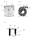
- FIG 2 shows two schematic representations of storage containers (2) for test elements (20).
- 2A is a Cross section parallel to the top of the storage container shown.
- a spiral (15) inside the storage container stabilizes a spiral winding of Test elements as shown in Figure 2B.
- the tape (16) both for the mechanical connection of the test elements as well as their Sealing serves.
- the volume (16) an aluminum foil is used.
- the band (16) is in the Threaded winding core (17).
- the belt (16) with a roller (18) small diameter which both the transport of the Arrangement of test elements in the direction of the opening (9) of the Storage container (2) as well as the detachment of the tape (16) by the test element (20) caused by the opening (9) of the storage container occurs.
- FIG. 3 shows a single test element (20) in a sealed Shape.
- the translucent pin (21) consists of Polycarbonate and has a fin (22) that is used for injection molding of the pen arises.
- the translucent pin (21) is this fin (22) essential since it ensures that structural disruptions of the Plastic are shifted to this area and thus be kept out of the light path.
- the translucent Pin (21) is surrounded by a jacket (23) made of polyethylene, that on the side of the tape (16) over the translucent Pin (21) protrudes. Because the refractive indices strongly differentiate from polycarbonate and polyethylene, becomes the condition for total reflection at the interface Fulfills.
- test field (24) and the Shell surface of the translucent pin (21) are with a thin aluminum layer of about 70 mm.
- the Space above the test field is through the aluminum foil (16) water-vapor proof against the environment.
- the The reagent layer of the test field (24) therefore does not come directly in contact with air humidity.
- Figure 4 shows schematically the transport of a test element (20) from the storage container (2) to the place Sample application.
- To Switching on takes place within a few millimeters of the device.
- a memory key can return previous results in this position can be called up and displayed from the memory.
- a rest point is exceeded, that blocks a reversal of movement. From this The entire analysis process must be run through.
- the cone (7) is designed that a dust cover when the test element penetrates is folded away or pushed aside. When reached the trial position protrudes the upper end of the Test element (20) about 2.0 to 2.5 mm out of the device. Through the cone (7) the surface of the test element protrude about 8 to 12 mm above the main contour of the device (1).
- Test element Under processing the already wound Aluminum foil from the winding core (17) up to 3 mm pushed back into a defined starting position. Thereby ensures that there are no positioning problems in Result of slightly different winding distances with increasing Coil diameter occur.
- a drop of blood of a few ⁇ l is sufficient as a sample.
- a hydrophobic plastic such as polypropylene (PP) or polyethylene (PE) for the jacket of the test element and PP or polyvinylidene fluoride (PVDF) for the cone (7) causes the blood not to pass through the reagent layer (24) spreads out onto the device. Rather, a larger sample offer a small spherical drop the detection district, while the larger amount on the skin of the patient remains. Drips on a heavily bleeding Patient's blood in free fall to the trial site, so the hydrophobic materials reduce the possibility that the blood gets into the device and contaminates it. Through a tight fit and, if necessary, a sealing lip The contamination safety can continue at the cone (7) increase. Should cleaning be necessary, this is facilitated by a removable version of the cone (7) become.
- PP polypropylene
- PE polyethylene
- PVDF polyvinylidene fluoride
- the sample application can be changed by changing the optical Properties of the test element (20) independently of the device be recognized.
- the measured value can be displayed by a be accompanied by an acoustic signal.
- the housing is after Overcoming a lock pushed another 2.5 mm.
- the spring returns to the initial state.
Landscapes
- Health & Medical Sciences (AREA)
- Physics & Mathematics (AREA)
- Life Sciences & Earth Sciences (AREA)
- Engineering & Computer Science (AREA)
- Biomedical Technology (AREA)
- Chemical & Material Sciences (AREA)
- Biochemistry (AREA)
- General Health & Medical Sciences (AREA)
- General Physics & Mathematics (AREA)
- Immunology (AREA)
- Pathology (AREA)
- Analytical Chemistry (AREA)
- Hematology (AREA)
- Medicinal Chemistry (AREA)
- Biophysics (AREA)
- Spectroscopy & Molecular Physics (AREA)
- Molecular Biology (AREA)
- Urology & Nephrology (AREA)
- Food Science & Technology (AREA)
- Optics & Photonics (AREA)
- Investigating Or Analysing Biological Materials (AREA)
- Automatic Analysis And Handling Materials Therefor (AREA)
- Investigating Or Analyzing Non-Biological Materials By The Use Of Chemical Means (AREA)
- Investigating Or Analysing Materials By The Use Of Chemical Reactions (AREA)
- Investigating Or Analysing Materials By Optical Means (AREA)
- Sampling And Sample Adjustment (AREA)
Claims (17)
- Système pour l'analyse d'échantillons liquides, comprenant :un appareil de mesure (1) doté d'une source de rayonnement, d'un réceptéur de rayonnement, d'un dispositif d'évaluation et d'affichage, ainsi queun récipient de réserve (2) pour recevoir des éléments de test, les éléments de test (20) étant scellés sur une feuille (16) de telle sorte que des champs de test (24) soient enfermés de manière étanche à la vapeur d'eau par le scellement des éléments de test sur la feuille.
- Système selon la revendication 1, dans lequel le transport d'un élément de test hors du récipient de réserve s'effectue au moyen de la feuille.
- Système selon la revendication 1 ou 2, dans lequel l'accès au champ de test (24) de l'élément de test est réalisé en arrachant la feuille de l'élément de test.
- Système selon la revendication 1, dans lequel l'élément de test possède une tige (21) qui est entourée par une enveloppe (23) qui déborde au-dessus de la tige et qui est fixée sur la feuille.
- Système selon la revendication 1 ou 4, dans lequel les éléments de test (20) possèdent un champ de test (24) sur le côté frontal dune tige transparente à la lumière.
- Système selon la revendication 1, dans lequel les éléments de test (20) sont reliés les uns aux autres par la feuille (16), le système possédant des dispositifs (17, 18) avec lesquels les éléments de test reliés par la feuille sont transportés dans le récipient de réserve (2) par enroulement de la feuille sur un mandrin d'enroulement (17), un élément de test qui sort du récipient de réserve étant libéré de la feuille (16) par un rouleau (18) ou une arête.
- Système selon la revendication 1, dans lequel la source de rayonnement et le récepteur de rayonnement sont disposés sur le côté du champ de test situé en face de l'application des échantillons.
- Système selon la revendication 1, qui possède une tige (26) avec une optique (25), la tige (26) pouvant exécuter un déplacement relatif, de telle sorte qu'un transport d'un élément de test depuis l'ouverture du récipient de réserve jusque dans une position d'application de l'échantillon peut s'effectuer à l'aide de la tige (26).
- Système selon la revendication 1, dans lequel une spirale (15) qui stabilise un agencement en spirale d'éléments de test se trouve à l'intérieur du récipient de réserve.
- Récipient de réserve (2) pour éléments de test (20) en vue de l'analyse d'échantillons liquides, contenant un agencement d'éléments de test qui sont scellés sur une feuille (16) de telle sorte que des champs de test situés sur les éléments de test (24) soient enfermés de manière étanche à la vapeur d'eau par le scellement des éléments de test sur la feuille.
- Récipient de réserve selon la revendication 10, présentant à l'intérieur une spirale (15) qui stabilise un agencement en spirale d'éléments de test.
- Récipient de réserve selon la revendication 10, caractérisé en ce que la feuille est fixée sur une enveloppe (23) de chaque élément de test (20) de telle sorte que le champ de test (24) soit protégé contre la pénétration d'humidité de l'air.
- Récipient de réserve selon la revendication 10, contenant une arête ou rouleau (18) sur lequel la feuille peut être tirée pour libérer un élément de test de la feuille.
- Procédé pour l'analyse d'échantillons liquides à l'aide d'éléments de test (20) qui sont scellés sur une feuille (16) et reliés les uns aux autres par la feuille, lequel procédé comprend les étapes consistant à :a) transporter un élément de test hors d'un récipient de réserve au moyen de la feuille (16),b) ouvrir le scellement de l'élément de test par arrachement de la feuille de l'élément de test de manière à rendre accessible un champ de test (24) de l'élément de test,c) application d'un échantillon liquide sur l'élément de test,d) exécution de l'opération de mesure sous irradiation de l'élément de test et mesure du rayonnement réfléchi ou du rayonnement transmis,e) calcul d'un résultat d'analyse à partir de la mesure, etf) expulsion de l'élément de test usagé hors du système.
- Procédé selon la revendication 14, dans lequel, dans l'étape a), la feuille (16) est enroulée à l'aide d'un mandrin d'enroulement (17) et, dans l'étape b), l'arrachage de la feuille (16) de l'élément de test s'effectue en faisant passer la feuille (16) autour d'un rouleau (18) ou d'une arête.
- Agencement d'éléments de test (20), dans lequel les éléments de test sont scellés sur une feuille (16) essentiellement imperméable à la vapeur d'eau, de telle sorte que les champs de test (24) des éléments de test soient protégés contre une pénétration de vapeur d'eau par le scellement sur la feuille.
- Agencement d'éléments de test (20) selon la revendication 16, dans lequel la feuille est fixée sur une enveloppe (23) de chaque élément de test (20).
Applications Claiming Priority (2)
| Application Number | Priority Date | Filing Date | Title |
|---|---|---|---|
| DE4326339 | 1993-08-05 | ||
| DE4326339A DE4326339A1 (de) | 1993-08-05 | 1993-08-05 | System zur Analyse von Probenflüssigkeiten |
Publications (3)
| Publication Number | Publication Date |
|---|---|
| EP0637749A2 EP0637749A2 (fr) | 1995-02-08 |
| EP0637749A3 EP0637749A3 (fr) | 1997-02-26 |
| EP0637749B1 true EP0637749B1 (fr) | 2002-10-23 |
Family
ID=6494549
Family Applications (1)
| Application Number | Title | Priority Date | Filing Date |
|---|---|---|---|
| EP94111934A Expired - Lifetime EP0637749B1 (fr) | 1993-08-05 | 1994-07-30 | Système d'analyse des échantillons liquides |
Country Status (6)
| Country | Link |
|---|---|
| US (2) | US5609823A (fr) |
| EP (1) | EP0637749B1 (fr) |
| JP (1) | JP2610109B2 (fr) |
| AT (1) | ATE226725T1 (fr) |
| DE (2) | DE4326339A1 (fr) |
| ES (1) | ES2185637T3 (fr) |
Cited By (1)
| Publication number | Priority date | Publication date | Assignee | Title |
|---|---|---|---|---|
| US8192372B2 (en) | 2001-06-08 | 2012-06-05 | Roche Diagnostics Operations, Inc. | Test media cassette for bodily fluid testing device |
Families Citing this family (59)
| Publication number | Priority date | Publication date | Assignee | Title |
|---|---|---|---|---|
| ZA976223B (en) * | 1996-07-17 | 1998-09-01 | Akzo Nobel Nv | Spiral cuvette loading device of an automated sample testing machine |
| US5736103A (en) * | 1996-08-09 | 1998-04-07 | Lifescan, Inc. | Remote-dosing analyte concentration meter |
| US5753429A (en) * | 1996-08-09 | 1998-05-19 | Lifescan, Inc. | Analyte concentration measurement using a hollow frustum |
| FI112029B (fi) * | 1996-09-02 | 2003-10-31 | Nokia Corp | Laite nestemäisten näytteiden, kuten verinäytteiden ottamiseksi ja analysoimiseksi |
| DE19714674A1 (de) * | 1997-04-09 | 1998-10-15 | Lre Technology Partner Gmbh | Teststreifenpackung und Meßgerät zur Verwendung einer solchen |
| GB9824627D0 (en) * | 1998-11-11 | 1999-01-06 | Cambridge Sensors Ltd | Test strips for small volumes |
| WO1999039186A1 (fr) * | 1998-02-02 | 1999-08-05 | Crystal Medical Products | Systeme de detection |
| US6207110B1 (en) | 1998-08-21 | 2001-03-27 | Bayer Corporation | Metallic overcoating as a light attenuating layer for optical sensors |
| DE19933458B4 (de) * | 1999-07-15 | 2015-08-20 | Eppendorf Ag | Einrichtungen und Systeme zum Handhaben von Flüssigkeitsproben |
| HK1053151B (en) * | 2000-03-28 | 2006-05-26 | Diabetes Diagnostics, Inc. | Continuous process for manufacture of disposable electro-chemical sensor |
| DE10105549A1 (de) * | 2001-02-06 | 2002-08-29 | Roche Diagnostics Gmbh | System zur Überwachung der Konzentration von Analyten in Körperflüssigkeiten |
| JP4522014B2 (ja) * | 2001-04-18 | 2010-08-11 | パナソニック株式会社 | バイオセンサシート、バイオセンサカートリッジ、およびバイオセンサ分与装置 |
| US7776608B2 (en) * | 2001-07-09 | 2010-08-17 | Bayer Healthcare Llc | Volume meter testing device and method of use |
| US7723113B2 (en) * | 2001-08-20 | 2010-05-25 | Bayer Healthcare Llc | Packaging system for test sensors |
| US6749887B1 (en) * | 2001-11-28 | 2004-06-15 | Lifescan, Inc. | Solution drying system |
| CA2419905C (fr) * | 2002-03-18 | 2016-01-05 | Bayer Healthcare, Llc | Cartouche de rangement pour biocapteurs |
| DE10244775A1 (de) * | 2002-09-26 | 2004-04-08 | Roche Diagnostics Gmbh | Kapillarsensor-Analysesystem |
| EP1424040A1 (fr) * | 2002-11-26 | 2004-06-02 | Roche Diagnostics GmbH | Dispositif de test pour fluides corporels |
| US7481777B2 (en) | 2006-01-05 | 2009-01-27 | Roche Diagnostics Operations, Inc. | Lancet integrated test element tape dispenser |
| US8153081B2 (en) * | 2003-05-29 | 2012-04-10 | Bayer Healthcare Llc | Test sensor and method for manufacturing the same |
| US7364699B2 (en) * | 2003-06-18 | 2008-04-29 | Bayer Healthcare Llc | Containers for reading and handling diagnostic reagents and methods of using the same |
| DE10348283A1 (de) * | 2003-10-17 | 2005-05-12 | Roche Diagnostics Gmbh | Handgerät zur Untersuchung einer Körperflüssigkeit |
| US8591436B2 (en) | 2004-04-30 | 2013-11-26 | Roche Diagnostics Operations, Inc. | Lancets for bodily fluid sampling supplied on a tape |
| AU2005201576B2 (en) * | 2004-05-07 | 2010-06-24 | F. Hoffmann-La Roche Ag | Process and device for producing an analytical tape for liquid samples |
| US7512432B2 (en) * | 2004-07-27 | 2009-03-31 | Abbott Laboratories | Sensor array |
| US20090294323A1 (en) * | 2004-10-01 | 2009-12-03 | Lawrence Luciano | Spiral medication packaging system and method |
| DE102004050062A1 (de) * | 2004-10-13 | 2006-04-27 | Boehringer Ingelheim Microparts Gmbh | Vorrichtung, Meßgerät und Verfahren zur Aufnahme und Untersuchung oder Manipulation von Probenflüssigkeiten in einer mikrofluidischen Plattform |
| DE102004060322A1 (de) | 2004-12-15 | 2006-06-22 | Roche Diagnostics Gmbh | Analysesystem mit einem elektrischen Anschlusssystem für ein Testelement |
| JP2006170974A (ja) | 2004-12-15 | 2006-06-29 | F Hoffmann-La Roche Ag | 分析試験エレメント上での液体試料の分析用分析システム |
| DE102006011265A1 (de) * | 2005-03-11 | 2006-10-12 | The Colman Group, Inc., Elkhorn | Teststreifenspender und Thermometerhalter |
| EP1712910A1 (fr) * | 2005-04-12 | 2006-10-18 | F.Hoffmann-La Roche Ag | Appareil d'analyse pour analyser un échantillon liquide utilisant un élément de test |
| US8192599B2 (en) * | 2005-05-25 | 2012-06-05 | Universal Biosensors Pty Ltd | Method and apparatus for electrochemical analysis |
| US8323464B2 (en) * | 2005-05-25 | 2012-12-04 | Universal Biosensors Pty Ltd | Method and apparatus for electrochemical analysis |
| US8016154B2 (en) * | 2005-05-25 | 2011-09-13 | Lifescan, Inc. | Sensor dispenser device and method of use |
| US7749371B2 (en) * | 2005-09-30 | 2010-07-06 | Lifescan, Inc. | Method and apparatus for rapid electrochemical analysis |
| CN101277647A (zh) * | 2005-10-12 | 2008-10-01 | 奥普斯特护理公司 | 监测分娩过程的方法 |
| EP1815785A1 (fr) * | 2006-02-02 | 2007-08-08 | Bioception B.V.i.o. | Dispositif en forme d'une cassette pour le diagnostic de fluides |
| US7638095B2 (en) * | 2006-02-10 | 2009-12-29 | Roche Diagnostics Operations, Inc. | Personal portable blood glucose meter with replaceable cartridge of test strips |
| US8388906B2 (en) * | 2006-03-13 | 2013-03-05 | Nipro Diagnostics, Inc. | Apparatus for dispensing test strips |
| US8388905B2 (en) * | 2006-03-13 | 2013-03-05 | Nipro Diagnostics, Inc. | Method and apparatus for coding diagnostic meters |
| US8940246B2 (en) | 2006-03-13 | 2015-01-27 | Nipro Diagnostics, Inc. | Method and apparatus for coding diagnostic meters |
| US11559810B2 (en) | 2006-03-13 | 2023-01-24 | Trividia Health, Inc. | Method and apparatus for coding diagnostic meters |
| US20100009455A1 (en) * | 2006-05-08 | 2010-01-14 | Dosmann Andrew J | Test Sensor with Under-Fill Protection |
| WO2007147494A2 (fr) * | 2006-06-23 | 2007-12-27 | Roche Diagnostics Gmbh | Système de conditionnement |
| PL1873521T3 (pl) * | 2006-06-27 | 2012-02-29 | Hoffmann La Roche | Diagnostyczna kaseta z taśmą |
| JP5285622B2 (ja) * | 2007-01-13 | 2013-09-11 | エフ ホフマン−ラ ロッシュ アクチェン ゲゼルシャフト | 穿刺装置 |
| US20080286149A1 (en) * | 2007-05-14 | 2008-11-20 | Roe Steven N | Bodily fluid sampling with test strips hinged on a tape |
| US8001825B2 (en) * | 2007-11-30 | 2011-08-23 | Lifescan, Inc. | Auto-calibrating metering system and method of use |
| EP2208995A1 (fr) | 2009-01-15 | 2010-07-21 | Roche Diagnostics GmbH | Bande de support pliée dotée d'éléments d'utilisation |
| AU2010237530B2 (en) | 2009-04-14 | 2016-04-21 | Biocartis Nv | HIFU induced cavitation with reduced power threshold |
| WO2010118541A1 (fr) | 2009-04-15 | 2010-10-21 | Biocartis Sa | Système de détection optique pour une réaction d'amplification en chaîne par polymérase (acp) en temps réel |
| EP2419220B1 (fr) | 2009-04-15 | 2018-06-06 | Biocartis NV | Protection de chambres à échantillons bioanalytiques |
| EP2427270B1 (fr) | 2009-05-06 | 2015-04-01 | Biocartis NV | Dispositif de coupe d'un porte-échantillon |
| US8574510B2 (en) * | 2009-09-30 | 2013-11-05 | Bayer Healthcare Llc | Stackable electrochemical analyte sensors, systems and methods including same |
| CA2904665A1 (fr) | 2013-03-11 | 2014-10-09 | Bayer Healthcare Llc | Dispositif de saisie de bande |
| US9376708B2 (en) | 2013-03-13 | 2016-06-28 | Ascensia Diabetes Care Holdings Ag | Bottled glucose sensor with no handling |
| WO2015053795A1 (fr) * | 2013-10-11 | 2015-04-16 | Draeger Safety, Inc. | Système de surveillance de gaz colorimétrique équipé d'un magasin de stockage pour des éléments de test jetables |
| JP2015232550A (ja) * | 2014-05-13 | 2015-12-24 | アークレイ株式会社 | センサ体、センサ体の製造方法及びセンサカートリッジ |
| DE102016202428B4 (de) * | 2016-02-17 | 2018-06-21 | Axagarius Gmbh & Co. Kg | Messsystem für colorimetrische Assays |
Family Cites Families (20)
| Publication number | Priority date | Publication date | Assignee | Title |
|---|---|---|---|---|
| US3526480A (en) * | 1966-12-15 | 1970-09-01 | Xerox Corp | Automated chemical analyzer |
| US3932133A (en) * | 1973-07-31 | 1976-01-13 | Olympus Optical Co., Ltd. | System for detecting the particular chemical component of a test fluid |
| US3918910A (en) * | 1973-07-31 | 1975-11-11 | Olympus Optical Co | System for detecting the particular chemical constituent of a fluid |
| US4218421A (en) * | 1978-08-18 | 1980-08-19 | Honeywell Inc. | Disposable container for a continuous band of test strips |
| US4301414A (en) * | 1979-10-29 | 1981-11-17 | United States Surgical Corporation | Disposable sample card and method of making same |
| JPS6142107Y2 (fr) * | 1979-11-30 | 1986-11-29 | ||
| DE8033593U1 (de) * | 1980-12-18 | 1981-07-09 | Behringwerke Ag, 3550 Marburg | Vorrichtung zum transport streifenfoermigen testguts unter eine messeinrichtung |
| FR2502779A1 (fr) * | 1981-03-26 | 1982-10-01 | Lre Relais & Elektronik Gmbh | Appareil de mesure permettant l'analyse opto-electronique de bandes de papier reactif |
| JP2533843B2 (ja) * | 1985-05-11 | 1996-09-11 | オリンパス光学工業株式会社 | 免疫学的分析に用いられる担体収納容器 |
| JPH076918B2 (ja) * | 1986-02-07 | 1995-01-30 | 富士写真フイルム株式会社 | 化学分析装置 |
| JPS63259469A (ja) * | 1987-04-16 | 1988-10-26 | Fuji Photo Film Co Ltd | 化学分析スライド包装体の開装装置 |
| JPS63308544A (ja) * | 1987-06-10 | 1988-12-15 | Fuji Photo Film Co Ltd | 化学分析スライド供給装置 |
| US5077010A (en) * | 1987-07-15 | 1991-12-31 | Fuji Photo Film Co., Ltd. | Long-test-film cassette for biochemical analysis, and system for loading the same |
| JPH01131460A (ja) * | 1987-08-31 | 1989-05-24 | Sekisui Chem Co Ltd | 免疫測定用ビーズおよびこれを用いる免疫測定法 |
| US5096828A (en) * | 1987-12-25 | 1992-03-17 | Fuji Photo Film Co., Ltd. | Biochemical analysis method |
| JPH04112785A (ja) * | 1990-09-03 | 1992-04-14 | Omron Corp | イオン・センシング・テープ,酵素テープ,テープ・カセットおよびこれらを用いたセンサ |
| JPH055734A (ja) * | 1991-08-22 | 1993-01-14 | Fuji Photo Film Co Ltd | 生化学分析装置 |
| FR2694434B1 (fr) * | 1992-07-29 | 1999-03-12 | Christian Cailbault | Appareil de distribution automatique de produits alimentaires. |
| DE4227678A1 (de) * | 1992-08-21 | 1994-02-24 | Boehringer Mannheim Gmbh | Lichtleitendes Analyseelement zur Bestimmung eines Analyten |
| US5268059A (en) * | 1992-09-02 | 1993-12-07 | Vlsi Technology, Inc. | Detaping machine for removal of integrated circuit devices from sealed pocket tape |
-
1993
- 1993-08-05 DE DE4326339A patent/DE4326339A1/de not_active Withdrawn
-
1994
- 1994-07-29 US US08/282,149 patent/US5609823A/en not_active Expired - Lifetime
- 1994-07-30 AT AT94111934T patent/ATE226725T1/de not_active IP Right Cessation
- 1994-07-30 DE DE59410199T patent/DE59410199D1/de not_active Expired - Lifetime
- 1994-07-30 ES ES94111934T patent/ES2185637T3/es not_active Expired - Lifetime
- 1994-07-30 EP EP94111934A patent/EP0637749B1/fr not_active Expired - Lifetime
- 1994-08-03 JP JP6182629A patent/JP2610109B2/ja not_active Expired - Lifetime
-
1996
- 1996-11-13 US US08/748,916 patent/US5679311A/en not_active Expired - Lifetime
Cited By (2)
| Publication number | Priority date | Publication date | Assignee | Title |
|---|---|---|---|---|
| US8192372B2 (en) | 2001-06-08 | 2012-06-05 | Roche Diagnostics Operations, Inc. | Test media cassette for bodily fluid testing device |
| US8257277B2 (en) | 2001-06-08 | 2012-09-04 | Roche Diagnostics Operations, Inc. | Test media cassette for bodily fluid testing device |
Also Published As
| Publication number | Publication date |
|---|---|
| DE4326339A1 (de) | 1995-02-09 |
| ES2185637T3 (es) | 2003-05-01 |
| US5609823A (en) | 1997-03-11 |
| JP2610109B2 (ja) | 1997-05-14 |
| US5679311A (en) | 1997-10-21 |
| JPH0777528A (ja) | 1995-03-20 |
| DE59410199D1 (de) | 2002-11-28 |
| ATE226725T1 (de) | 2002-11-15 |
| EP0637749A3 (fr) | 1997-02-26 |
| EP0637749A2 (fr) | 1995-02-08 |
Similar Documents
| Publication | Publication Date | Title |
|---|---|---|
| EP0637749A2 (fr) | Système d'analyse des échantillons liquides | |
| EP1130383B1 (fr) | Disquette avec des elements d'analyse arrangé en cercle | |
| EP0951939B1 (fr) | Dispositif de stockage d'éléments d'analyse | |
| DE4313253A1 (de) | System zur Analyse von Inhaltsstoffen flüssiger Proben | |
| US8252248B2 (en) | Analytical test element | |
| EP1663000B1 (fr) | Dispositif d'essai pour examiner des liquides organiques | |
| EP0640393B1 (fr) | Dispositif pour l'approvisionnement d'éléments de test | |
| DE69609445T2 (de) | Vorrichtung zum Handhaben einer Vielzahl von Sensoren | |
| DE1673342B2 (de) | Reaktionsbehälter aus flexiblem Material | |
| DE19755529A1 (de) | Analysensystem für Probenflüssigkeiten | |
| DE69018892T2 (de) | Automatischer Analysator. | |
| EP0425587B1 (fr) | Procede pour la mise en evidence d'activites biologiques dans un echantillon et dispositif pour la mise en oeuvre de ce procede | |
| US5135313A (en) | Chain-of-custody bag | |
| EP1712910A1 (fr) | Appareil d'analyse pour analyser un échantillon liquide utilisant un élément de test | |
| US5160329A (en) | Biological fluid specimen collection bag | |
| EP0830585B1 (fr) | Porte-echantillon pour spectroscopie par transmission infrarouge | |
| DE9418146U1 (de) | Lesevorrichtungen und Assayvorrichtungen zur Verwendung damit | |
| DE1673340A1 (de) | Chemische Analysierungseinrichtung | |
| EP3646003A1 (fr) | Récipient comportant une saillie de paroi et une zone de capteur | |
| DE69319272T2 (de) | Kassette zur Lagerung trocken-analytischer Filmstreifen | |
| US20100178204A1 (en) | Automated Self-Contained Liquid Handling and Detection System Device | |
| DE1941572A1 (de) | Vorrichtung und Verfahren fuer die photometrische Analyse von Fluessigkeiten | |
| US5217443A (en) | Biological fluid specimen collection bag | |
| DE102007034155A1 (de) | Vorrichtung mit mindestens einer Verpackungseinheit mit einem zur Radiofrequenz-Identifikation dienenden RFID-Chip und Verfahren dazu | |
| EP3536349A1 (fr) | Unité d'analyse |
Legal Events
| Date | Code | Title | Description |
|---|---|---|---|
| PUAI | Public reference made under article 153(3) epc to a published international application that has entered the european phase |
Free format text: ORIGINAL CODE: 0009012 |
|
| 17P | Request for examination filed |
Effective date: 19940730 |
|
| AK | Designated contracting states |
Kind code of ref document: A2 Designated state(s): AT BE CH DE DK ES FR GB IT LI NL SE |
|
| PUAL | Search report despatched |
Free format text: ORIGINAL CODE: 0009013 |
|
| AK | Designated contracting states |
Kind code of ref document: A3 Designated state(s): AT BE CH DE DK ES FR GB IT LI NL SE |
|
| RAP3 | Party data changed (applicant data changed or rights of an application transferred) |
Owner name: ROCHE DIAGNOSTICS GMBH |
|
| 17Q | First examination report despatched |
Effective date: 19991213 |
|
| GRAG | Despatch of communication of intention to grant |
Free format text: ORIGINAL CODE: EPIDOS AGRA |
|
| GRAG | Despatch of communication of intention to grant |
Free format text: ORIGINAL CODE: EPIDOS AGRA |
|
| GRAG | Despatch of communication of intention to grant |
Free format text: ORIGINAL CODE: EPIDOS AGRA |
|
| GRAH | Despatch of communication of intention to grant a patent |
Free format text: ORIGINAL CODE: EPIDOS IGRA |
|
| GRAH | Despatch of communication of intention to grant a patent |
Free format text: ORIGINAL CODE: EPIDOS IGRA |
|
| GRAA | (expected) grant |
Free format text: ORIGINAL CODE: 0009210 |
|
| AK | Designated contracting states |
Kind code of ref document: B1 Designated state(s): AT BE CH DE DK ES FR GB IT LI NL SE |
|
| PG25 | Lapsed in a contracting state [announced via postgrant information from national office to epo] |
Ref country code: NL Free format text: LAPSE BECAUSE OF FAILURE TO SUBMIT A TRANSLATION OF THE DESCRIPTION OR TO PAY THE FEE WITHIN THE PRESCRIBED TIME-LIMIT Effective date: 20021023 |
|
| REF | Corresponds to: |
Ref document number: 226725 Country of ref document: AT Date of ref document: 20021115 Kind code of ref document: T |
|
| REG | Reference to a national code |
Ref country code: GB Ref legal event code: FG4D Free format text: NOT ENGLISH |
|
| REG | Reference to a national code |
Ref country code: CH Ref legal event code: EP |
|
| REF | Corresponds to: |
Ref document number: 59410199 Country of ref document: DE Date of ref document: 20021128 |
|
| PG25 | Lapsed in a contracting state [announced via postgrant information from national office to epo] |
Ref country code: SE Free format text: LAPSE BECAUSE OF FAILURE TO SUBMIT A TRANSLATION OF THE DESCRIPTION OR TO PAY THE FEE WITHIN THE PRESCRIBED TIME-LIMIT Effective date: 20030123 Ref country code: DK Free format text: LAPSE BECAUSE OF FAILURE TO SUBMIT A TRANSLATION OF THE DESCRIPTION OR TO PAY THE FEE WITHIN THE PRESCRIBED TIME-LIMIT Effective date: 20030123 |
|
| GBT | Gb: translation of ep patent filed (gb section 77(6)(a)/1977) |
Effective date: 20030204 |
|
| NLV1 | Nl: lapsed or annulled due to failure to fulfill the requirements of art. 29p and 29m of the patents act | ||
| REG | Reference to a national code |
Ref country code: ES Ref legal event code: FG2A Ref document number: 2185637 Country of ref document: ES Kind code of ref document: T3 |
|
| ET | Fr: translation filed | ||
| PG25 | Lapsed in a contracting state [announced via postgrant information from national office to epo] |
Ref country code: AT Free format text: LAPSE BECAUSE OF NON-PAYMENT OF DUE FEES Effective date: 20030730 |
|
| PG25 | Lapsed in a contracting state [announced via postgrant information from national office to epo] |
Ref country code: LI Free format text: LAPSE BECAUSE OF NON-PAYMENT OF DUE FEES Effective date: 20030731 Ref country code: CH Free format text: LAPSE BECAUSE OF NON-PAYMENT OF DUE FEES Effective date: 20030731 Ref country code: BE Free format text: LAPSE BECAUSE OF NON-PAYMENT OF DUE FEES Effective date: 20030731 |
|
| PLBE | No opposition filed within time limit |
Free format text: ORIGINAL CODE: 0009261 |
|
| STAA | Information on the status of an ep patent application or granted ep patent |
Free format text: STATUS: NO OPPOSITION FILED WITHIN TIME LIMIT |
|
| 26N | No opposition filed |
Effective date: 20030724 |
|
| BERE | Be: lapsed |
Owner name: *ROCHE DIAGNOSTICS G.M.B.H. Effective date: 20030731 |
|
| REG | Reference to a national code |
Ref country code: CH Ref legal event code: PL |
|
| PGFP | Annual fee paid to national office [announced via postgrant information from national office to epo] |
Ref country code: GB Payment date: 20130624 Year of fee payment: 20 |
|
| PGFP | Annual fee paid to national office [announced via postgrant information from national office to epo] |
Ref country code: ES Payment date: 20130705 Year of fee payment: 20 Ref country code: DE Payment date: 20130731 Year of fee payment: 20 |
|
| PGFP | Annual fee paid to national office [announced via postgrant information from national office to epo] |
Ref country code: FR Payment date: 20130712 Year of fee payment: 20 |
|
| PGFP | Annual fee paid to national office [announced via postgrant information from national office to epo] |
Ref country code: IT Payment date: 20130715 Year of fee payment: 20 |
|
| REG | Reference to a national code |
Ref country code: DE Ref legal event code: R071 Ref document number: 59410199 Country of ref document: DE |
|
| REG | Reference to a national code |
Ref country code: GB Ref legal event code: PE20 Expiry date: 20140729 |
|
| PG25 | Lapsed in a contracting state [announced via postgrant information from national office to epo] |
Ref country code: DE Free format text: LAPSE BECAUSE OF EXPIRATION OF PROTECTION Effective date: 20140731 |
|
| REG | Reference to a national code |
Ref country code: ES Ref legal event code: FD2A Effective date: 20141120 |
|
| PG25 | Lapsed in a contracting state [announced via postgrant information from national office to epo] |
Ref country code: GB Free format text: LAPSE BECAUSE OF EXPIRATION OF PROTECTION Effective date: 20140729 |
|
| PG25 | Lapsed in a contracting state [announced via postgrant information from national office to epo] |
Ref country code: ES Free format text: LAPSE BECAUSE OF EXPIRATION OF PROTECTION Effective date: 20140731 |