EP0637754A1 - Instrument de mesure de capacite pour batterie - Google Patents
Instrument de mesure de capacite pour batterie Download PDFInfo
- Publication number
- EP0637754A1 EP0637754A1 EP94904766A EP94904766A EP0637754A1 EP 0637754 A1 EP0637754 A1 EP 0637754A1 EP 94904766 A EP94904766 A EP 94904766A EP 94904766 A EP94904766 A EP 94904766A EP 0637754 A1 EP0637754 A1 EP 0637754A1
- Authority
- EP
- European Patent Office
- Prior art keywords
- battery
- remaining capacity
- value
- current
- values
- Prior art date
- Legal status (The legal status is an assumption and is not a legal conclusion. Google has not performed a legal analysis and makes no representation as to the accuracy of the status listed.)
- Granted
Links
Images


Classifications
-
- G—PHYSICS
- G01—MEASURING; TESTING
- G01R—MEASURING ELECTRIC VARIABLES; MEASURING MAGNETIC VARIABLES
- G01R31/00—Arrangements for testing electric properties; Arrangements for locating electric faults; Arrangements for electrical testing characterised by what is being tested not provided for elsewhere
- G01R31/36—Arrangements for testing, measuring or monitoring the electrical condition of accumulators or electric batteries, e.g. capacity or state of charge [SoC]
- G01R31/3644—Constructional arrangements
- G01R31/3648—Constructional arrangements comprising digital calculation means, e.g. for performing an algorithm
-
- G—PHYSICS
- G01—MEASURING; TESTING
- G01R—MEASURING ELECTRIC VARIABLES; MEASURING MAGNETIC VARIABLES
- G01R31/00—Arrangements for testing electric properties; Arrangements for locating electric faults; Arrangements for electrical testing characterised by what is being tested not provided for elsewhere
- G01R31/36—Arrangements for testing, measuring or monitoring the electrical condition of accumulators or electric batteries, e.g. capacity or state of charge [SoC]
- G01R31/382—Arrangements for monitoring battery or accumulator variables, e.g. SoC
- G01R31/3842—Arrangements for monitoring battery or accumulator variables, e.g. SoC combining voltage and current measurements
-
- G—PHYSICS
- G01—MEASURING; TESTING
- G01R—MEASURING ELECTRIC VARIABLES; MEASURING MAGNETIC VARIABLES
- G01R31/00—Arrangements for testing electric properties; Arrangements for locating electric faults; Arrangements for electrical testing characterised by what is being tested not provided for elsewhere
- G01R31/005—Testing of electric installations on transport means
- G01R31/006—Testing of electric installations on transport means on road vehicles, e.g. automobiles or trucks
Definitions
- This invention relates to a remaining capacity meter of a battery to be used as a driving source for electric motor vehicles, and particularly to a battery remaining capacity meter with which a usable capacity of the battery being used can be easily understood.
- a battery is generally used as a driving source for an electric motor in an electric motor vehicle such as an electric car.
- Several different methods are known for detecting the remaining capacity of the battery. Such methods can be classified into either 1) direct detection or 2) indirect detection of the remaining capacity.
- the first classification uses the relationship between the following essential battery characteristics and the battery remaining capacity. These characteristics include the open circuit voltage. electrolyte density, the electrode potential of a pair of reference electrodes, the pH value of the electrolyte, partial pressures of various gases in the cell, relative humidity in the cell dead space, the electrolyte viscosity, and the refractive index of the electrolyte.
- a numerical formula representing the relation between these characteristics and the remaining capacity varies depending on the type of battery.
- a sealed lead acid battery is generally recognized to have a linear correlation between the remaining capacity and the open circuit voltage.
- a 13V open circuit voltage corresponds to 27Ah, 12.4V to 15Ah, and 11.8V to 2Ah.
- a remaining capacity meter using this correlation is described in detail in Japanese Patent Application Laid-open Print No. 57-149144.
- An apparatus based on the relation between the density and the refractive index of the sulfuric acid electrolyte of a lead acid battery has also been used widely to detect the remaining capacity (e.g.. Japanese Patent Application Laid-open Print No. 63-274064 and Japanese Patent Application Laid-open Print No. 1-260769).
- a special probe is inserted into the battery to measure the refractive index of the sulfuric acid electrolyte. The remaining capacity is calculated from the detected values.
- the second classification indirect detection of a remaining capacity calculates a remaining capacity by measuring either the output current of the battery or the output current and voltage of the battery when the battery is being used as an energy source.
- I stands for the discharge current
- n for a value larger than 1 which depends on the type of battery
- t for the discharge time
- C for a constant.
- the PEUKERT equation yields values which correspond to the well-known phenomenon in which battery capacity decreases as the electric current increases. For example, in a 30Ah sealed lead acid battery, a 10A constant current discharge leads to a capacity of 26.6Ah, 50A to 17.0Ah, and 80A to 14.9Ah.
- a second indirect detection technique for determining battery remaining capacity uses the output current and the voltage of the battery (e.g., Japanese Patent Application Laid-open No. 2-247588). Specifically, in a table showing current on the horizontal axis and a voltage on the vertical axis, values corresponding to actual battery remaining capacities are indicated, and the table including these values is stored in a memory device which is a component of the remaining capacity meter.
- the direct detection technique which uses the open circuit voltage shows a correct value only when reaching an equilibrium voltage after an extended period of time.
- an electric motor vehicle such as an electric car actually runs in an urban area, it does not stop for long enough periods of time for the battery to reach the equilibrium voltage. As a result, the correct remaining value cannot be determined under these conditions.
- the insertion of the sensor for measuring the refractive index is expensive and has the disadvantage of increasing the possibility of electrolyte leakage from the point of sensor insertion. Additionally, it is difficult to position the sensor at an appropriate location within the battery such that a representative value can be measured.
- a method for detecting a remaining capacity which uses the PEUKERT equation to covert an input current signal, integrates the used battery capacity, and subtracts the integrated used capacity from the whole capacity, requires complicated circuitry which is expensive.
- Another problem with this method is that even when the battery has available remaining capacity, it may not be used for high current values because of large voltage drops. In this case, although the battery cannot be used because of the large voltage drops at that time, after a lapse of a certain time, the battery recovers and it may be used for high current values. In this case, the integration method indicates before and after recovery that there is no remaining capacity, causing the user to be confused. And, even if it is technically not an error, the remaining state of the battery is not indicated properly for both conditions, before and after recovery. That is to say, under the present method which uses the battery current, there is a disadvantage that the usable battery remaining capacity under all situations cannot be determined accurately.
- the indicating device either 1) indicating a capacity which varies greatly with the increase or decrease of current used or 2) indicates that remaining capacity can be used even when it cannot be used. In either case, the user has difficulty in understanding the indication of battery remaining capacity.
- this invention has been completed with the aim of realizing a battery remaining capacity meter using an inexpensive circuit structure, which can always make measurements regardless of the presence of a load, automatically corrects for differences in battery capacity due to the magnitude of a discharge current value, and always indicates a remaining capacity with respect to the current discharge current value. Furthermore, the capacity indication of the battery remaining capacity meter is designed to be similar to that of a fuel meter used in conventional internal combustion engine cars, so that the user can easily understand it.
- This invention relates to a battery remaining capacity meter which comprises: a detecting means for detecting the discharge current and the terminal voltage of a battery, a data table of remaining capacity values which corresponds to the combinations of current values at several different discharge currents and terminal voltage values and in which the remaining capacity values are based on actual values measured in advance, a memory for storing the above data table, and an indicating means for reading the remaining capacity value from the memory using the current value and the terminal voltage value of the operating battery and for giving instructions to a display, wherein the remaining capacity value is set as a ratio between a total time during which a constant current discharge can be made from an initial voltage in a fully charged state to an end voltage and a remaining time during which the constant current discharge can be made from the detected terminal voltage value to the end voltage.
- a data table of battery absolute capacity values at each measured current value according to Comparative Example 2 (unusable capacities are included in this table).
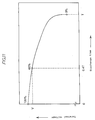
- a characteristic view showing the relation between a battery discharge voltage and a dischargeable capacity based on the discharge curve at a given constant current discharge.
- a data table of battery absolute capacity values usable at each measured current value according to the invention.
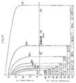
- the battery terminal voltage varies with the respect to the discharge time, as shown in Fig. 11. Specifically, as shown in the figure, the terminal voltage decreases gradually for most of the discharge time, then decreases sharply at a time T when the usable capacity of the battery is exhausted. Therefore, the discharge capacity usable at a certain time for this discharge condition can be represented by the product of the discharge current and the elapsed time up until the voltage drop point T.
- the discharge time is shortened as the constant-current discharge value increases, Specifically, as shown in Fig. 12, the time T at which the voltage drops sharply decreases significantly with the increase of the constant current discharge. Furthermore, the voltage at the time T also tends to decrease. Accordingly, as the discharge current increases, the dischargeable capacity decreases, and the discharge curves become different. As a result, when a fully charged battery is discharged at several different constant currents, the whole dischargeable capacity varies according to the current, and the dischargeable capacity can be determined as a function of each constant current. Specifically, as shown in Fig. 13, for example in the same battery having a nominal capacity of 30Ah, the dischargeable capacity decreases as the discharge current value increases.
- a discharge curve can be drawn using capacity instead of time on the horizontal axis and the terminal voltage on the vertical axis. Division of the voltage axis into several small ranges can generate the vertical component of a table which relates the dischargeable remaining capacity at a given time with the terminal voltage and the discharge current of the battery.
- a discharge current of 10A for example, a range from zero to time T on the horizontal axis is divided into five sections, so that a voltage range corresponding to each divided section can be obtained.
- the used current quantity (Ah) at this time can be calculated.
- the absolute remaining capacity value usable at each time can be obtained.
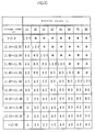
- a table for obtaining usable absolute capacity values of the battery can be obtained as shown in Fig. 15.
- Blocks (hereinafter referred to as cells) marked with an asterisk indicate that a combination of a given voltage and a given current cannot be attained.
- the absolute capacity values used in the aforementioned Fig. 15 are replaced by relative capacity values. And, as seen from the following examples and comparative examples, these relative values are used to realize a device which can simply determine the usable remaining capacity which varies according to the current values.
- a battery remaining capacity meter 1 comprises a detecting circuit block 3, a microcomputer block 5 connected to the above block, and a display 21 connected to the block 5.
- the detecting circuit block 3 is connected to the terminals of a battery which is not shown and comprises detecting circuits 11, 12 for detecting the battery current and voltage, filter circuits 13, 14 for filtering detection signals from these circuits 11, 12, and hold circuits 15, 16 for holding the filtered signals.
- the microcomputer block 5 comprises an A/D converter 17 for converting an analog signal from the detecting circuit into a digital signal, a microcomputer 18 for determining a battery remaining capacity value with reference to a table of a ROM 19 based on the digital signal, and a latch circuit for holding the remaining capacity value.
- the battery of this example is the aforementioned sealed lead acid battery having a nominal capacity of 30Ah to simplify the description.
- the above detecting circuits 11, 12 are connected to the battery terminals to detect the terminal voltage and the discharge current of the battery being used. Specifically, the terminal voltage is easily detected by resistance division. On the other hand, a discharge current can be detected by either a method using a shunt resistance connected in series with a load of the battery or a method using a current sensor with a Hall element.
- the detected analog signal having the a.c. component removed is converted into a digital signal by an A/D converter 17 through sample-hold circuits 15, 16 and outputted to the microcomputer 18.
- the microcomputer 18 reads the terminal voltage value and the discharge current value converted into the digital signal and obtains the remaining capacity value corresponding to a combination thereof from the ROM 19.
- the ROM (read-only memory) 19 has a data table of the remaining capacity value, to be described afterward, prepared based on values measured in advance and stored.
- the microcomputer 18 outputs binary data corresponding to the obtained remaining capacity value to a latch circuit 20.
- the binary data is data decoded to cause for example a display 21 to appropriately indicate the increase or decrease in the remaining capacity value.
- the latch circuit 20 is structured to hold the last data until new data comes from the microcomputer 18 and is output to the display 21.
- the display 21 indicates the increase or decrease of the remaining capacity value according to the data held in the latch circuit 20.
- a driving battery for electric-motor vehicles may be charged by regenerative braking when running.
- the remaining capacity value cannot be obtained from the data table in the ROM 19 because the battery is not discharged, and the discharge current and voltage values cannot be detected. Therefore, data of the microcomputer 10 is not outputted to the latch circuit 20 during this regeneration period. Accordingly, it is structured that during the period of regenerative braking, the remaining capacity value immediately before the regenerative braking is held and this remaining capacity value is indicated on the display 21.
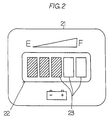
- the display 21 is provided with an LED module 22 consisting of five LEDs as shown in Fig. 2. These LEDs are arranged in a horizontal direction and designed to increase or decrease the number of illuminated LEDs from the left side in the figure according to the decoded data from the latch circuit 20. Specifically, when the remaining capacity value is 80% or more, the remaining capacity is determined to be F (full) and the display illuminates all five LEDs of the LED module 22. Similarly, when the remaining capacity value is 60% or more and less than 80%, four LEDs are illuminated. Thus, the number of illuminated LEDs is decreased by one at every 20%, and 0% or below is determined to be E (empty). In this condition, all LEDs are turned off. Therefore, in Fig. 2, three LEDs are illuminated, indicating that the battery remaining capacity at a certain current used is 40% or more and less than 60%.
- This invention is not limited to the indication of the increase or decrease of the illuminated number of LEDs of the display 21, but it may be structured to indicate by the increase or decrease of the display range, by a change of brightness, or by a change of a color.
- the above circuit structure is merely one example, and it may be a more simplified circuit structure by for example subjecting the detection data read in the microcomputer 18 to a digital low-pass filtering, so that the low-pass filters 13, 14 can be omitted.
- the sample-hold circuits 15, 16 may be one sample-hold circuit which is switched by time-sharing, so that further simplification can be made.
- an analog voltmeter may be used as the display.
- the data table stored in the ROM 19 is prepared from the actually measured data shown in Fig. 15 and has the characteristic that a relative value is used instead of an absolute capacity value.
- the maximum capacity value at each discharge current is determined to be 100%, and the remaining capacity value determined from this current value and the detection voltage at this time is indicated as a percentage with respect to the maximum capacity value.
- the total discharge time of the time axis is divided according to the indicated percentages, and a voltage range corresponding to the division is determined.
- the voltage detection value decreases, and moves from a cell of 10A-12.3V to a cell of 80A-11.2 to 11.39V in the data table of Fig. 3.
- the remaining capacity value of both cells has a value of 100%, and the remaining capacity meter indicates 100%.
- the indication by the remaining capacity meter is constant regardless of the magnitude of the discharge current since the remaining capacity is in the fully charged state. Therefore, even when the discharge current is quickly brought back to 10A, the remaining capacity indication does not change and remains as 100%.
- the remaining capacity indication lowers to 80%, but when the current is increased to 80A, the voltage lowers to 11.0 to 11.19V, and the corresponding remaining capacity value remains the same at 80%.
- the indication of 80% capacity is the same and the indication itself is continuously indicated.
- the voltage range also changes, and a cell indicating the remaining capacity moves, but the indicated value of the cell remains 0%.
- the change of the indicated value due to the movement between cells in adjacent columns is horizontal or on a diagonal line and is continuously smooth such that the indication does not change suddenly, preventing the user from being confused unnecessarily.
- the above structure of the invention allows measurements of remaining capacity regardless of the presence or absence of a load.
- the realization of the battery remaining capacity meter in a simple circuit structure can improve cost efficiency.
- the battery remaining capacity meter of the invention has an advantage that it is not necessary to make a temperature compensation due to a change of the electrolyte temperature in view of its operation.
- the battery terminal voltage decreases with the decrease of the electromotive force and the increase of the internal resistance, and the rate of decrease of the terminal voltage is accelerated for a constant current discharge because the rate of electrolyte diffusion is slowed.
- these phenomena are automatically corrected as a decrease of the remaining capacity value as the rate of decrease of the terminal voltage accelerates.
- the degradation of the battery performance can be recognized as a reduction of the remaining capacity after full charging.
- a remaining capacity meter which uses a current value as one of several variables for determining the remaining capacity, it needs to incorporate a function for correcting the indication of a remaining capacity according to increases or decreases in the electric current.
- This invention measures both a discharge current and a terminal voltage of a battery to determine the remaining capacity. According to a combination of these measured current and voltage values, a ratio of the usable remaining capacity at that current value is determined with reference to the remaining capacity value stored in table form in the memory.
- the remaining capacity values stored in the data table of the invention correspond to relative values. A range indicating the relative remaining capacities ranges from 100% for the fully charged battery to 0% for the battery in the empty state.
- the dischargeable capacity at each discharge current is determined by discharging the battery from the fully charged state to the cut-off voltage of the empty state.
- the dischargeable capacity at each current is divided at equal intervals such as 100%, 90%, 80%, 70%, 60%, 50%, 40%, 30%, 20%, 10%, and 0%.
- the measured voltage at each uniform division point and the discharge current corresponding to it form one horizontal row of Fig. 3. Therefore, using the relative remaining capacity values (0 to 100%) of the invention, for the change of indication by the remaining capacity meter as a function of electric current, it can be clearly seen that the rate of decrease of the indicated values from 100% to 0% will be accelerated with increasing current.
- the battery remaining capacity meter of the invention will be described based on Example 2 shown in Fig. 5.
- the battery remaining capacity meter of this example has the same structure as that of Example 1 except that the data table stored in the memory means, ROM, is changed.
- this data table is prepared by modifying the data table of Fig. 3 used in Example 1, and consists of current values of the operating battery in the horizontal direction and percent divisions corresponding to the indication division of the display means in the vertical direction. And, each block divided by these current values and percentage covers a voltage range meeting the percentage condition at each current from the data table of Fig. 5.
- the battery remaining capacity is determined from the voltage value detected at the current used with reference to the table. Specifically, it is structured that the reference row of the table is determined from the current used, a block is determined from the applicable detected voltage value in this reference row, and the remaining capacity percentage line corresponding to this block is determined.
- the battery remaining capacity meter of the invention will be described based on Example 3 shown in Fig. 6.
- the battery remaining capacity meter of this example has the same circuit structure as that of Example 1 and Example 2 except that the data table stored in the memory means, ROM, is changed.
- this data table has the same structure as the data table of Example 2, and the voltage value of each block is the lower limit value of each corresponding block used in the data table of Example 2.
- the battery remaining capacity is determined from the voltage value detected at the current used with reference to the table. Specifically, the reference row of this table is first determined from the current used. Then, the detected voltage value and the voltage value of each block are compared, and the block Pn which meets the condition, Pn ⁇ detected voltage value ⁇ Pn+1, is determined as the applicable block. Lastly, the remaining capacity percentage corresponding to the applicable block is determined, and the increase or decrease corresponding to this percentage is indicated on the display.
- the battery remaining capacity meter of the invention will be described based on Example 4 shown in Fig. 7.
- the battery remaining capacity meter of this example has the same circuit structure as that of Example 1 except that the data table stored in the ROM 19 is changed.
- this data table has the same structure as the data table of Example 2, and the voltage value of each block is the upper limit value of each corresponding block used in the data table of Example 2.
- the battery remaining capacity is determined from the voltage value detected at the current used with reference to the table. Specifically, the reference row of this table is first determined from the current used. Then, the detected voltage value and the voltage value of each block are compared, and the block Pn which meets the condition. Pn ⁇ detected voltage value ⁇ Pn+1, is determined as the applicable block. Lastly, the remaining capacity percentage corresponding to the applicable block is determined, and the increase or decrease corresponding to this percentage is indicated on the display.
- Example 3 the volume of data can be reduced, enabling simplification.
- Comparative Example 1 will be described with reference to Fig. 8.
- the same circuit structure of the battery remaining capacity meter as that shown in Fig. 1 of this invention will be used in this Comparative Example 1.
- the same display as that shown in Fig. 5 and used in Example 1 will be used.
- the structure for retaining the remaining capacity value immediately before the regenerative braking will be used in this Comparative Example 1.
- the data table stored in the memory, ROM 19, is prepared based on the absolute capacity data of Fig. 15. But, to indicate the remaining capacity using five LED modules, it is necessary to correct the obtained absolute capacity value into a percentage ranging from 0% to 100%. Specifically, when the maximum value (26.6Ah at a constant discharge rate of 10Ah) of the absolute capacity is defined as 100%, other values in the table are set as a percentage of this maximum capacity value.
- the data table thus obtained and actually stored in the ROM 19 is shown in Fig. 8.
- the display corresponds to the measured current-voltage, indicating 80% at a 10A discharge current (12.1 to 12.3V) and 40% at an 80A discharge current (11.0 to 11.19V). After reaching the 0% limit, regardless of the discharge current, the indication becomes 0% at all current levels.
- the display indicates drastic changes in the capacity indicating value for different current values when the battery is fully charged or nearly fully charged. The drastic changes in the capacity indicating value due to a change of the current value becomes less drastic only as the battery gets closer to the empty state. Thus, on the whole, it is difficult for the user to understand the condition of the battery from this display.
- Comparative Example 2 will be described with reference to Fig. 9 and Fig. 10. Comparative Example 2 uses the same circuit structure and display as in Example 1 of the invention. Therefore, the remaining capacity value immediately before regenerative braking is retained during the regenerative braking.
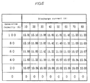
- the data table stored in the ROM 19 is prepared from the absolute capacity data of Fig. 9.
- the maximum capacity at each discharge current is defined again as 26.6Ah. This value is the maximum capacity within a range of current actually used.
- the absolute capacity data defined in this way when the discharge current is high, remaining capacity is indicated even after the cut-off voltage is reached and capacity cannot be withdrawn at this high current.
- the display shows drastic changes in the capacity indicating value as a function of the discharge current when the battery approaches the empty state.
- the drastic changes in capacity due to a change of the current become less drastic only as the battery gets closer to the fully charged state.
- the remaining capacity meter of this Comparative Example it is difficult for the user to understand the indicated value of the remaining capacity.
- the invention structured as described above is suitable for a remaining capacity meter of a battery used as a driving source for an electric motor vehicle such as an electric car.
Landscapes
- Physics & Mathematics (AREA)
- General Physics & Mathematics (AREA)
- Tests Of Electric Status Of Batteries (AREA)
- Charge And Discharge Circuits For Batteries Or The Like (AREA)
- Secondary Cells (AREA)
Applications Claiming Priority (7)
| Application Number | Priority Date | Filing Date | Title |
|---|---|---|---|
| JP1196693 | 1993-01-27 | ||
| JP11966/93 | 1993-01-27 | ||
| JP5-11966U JPH0666209U (ja) | 1993-02-22 | 電気機器収納用箱体の機器取り付け板の取り付け構造 | |
| JP126309/93 | 1993-05-27 | ||
| JP12630993 | 1993-05-27 | ||
| JP12630993 | 1993-05-27 | ||
| PCT/JP1994/000098 WO1994017425A1 (fr) | 1993-01-27 | 1994-01-25 | Instrument de mesure de capacite pour batterie |
Publications (3)
| Publication Number | Publication Date |
|---|---|
| EP0637754A1 true EP0637754A1 (fr) | 1995-02-08 |
| EP0637754A4 EP0637754A4 (fr) | 1995-07-19 |
| EP0637754B1 EP0637754B1 (fr) | 2002-09-25 |
Family
ID=26347488
Family Applications (1)
| Application Number | Title | Priority Date | Filing Date |
|---|---|---|---|
| EP94904766A Expired - Lifetime EP0637754B1 (fr) | 1993-01-27 | 1994-01-25 | Instrument de mesure de capacite pour batterie |
Country Status (2)
| Country | Link |
|---|---|
| EP (1) | EP0637754B1 (fr) |
| WO (1) | WO1994017425A1 (fr) |
Cited By (121)
| Publication number | Priority date | Publication date | Assignee | Title |
|---|---|---|---|---|
| EP0713101A3 (fr) * | 1994-11-21 | 1996-11-20 | Seiko Epson Corp | Appareil de mesure de la capacité résiduelle et méthode pour calculer la capacité résiduelle d'une batterie |
| FR2739452A1 (fr) * | 1995-09-29 | 1997-04-04 | Renault | Procede et dispositif de mesure de l'etat de charge d'une batterie |
| FR2740877A1 (fr) * | 1995-11-06 | 1997-05-09 | Renault | Procede pour determiner l'etat de charge d'une batterie d'accumulateurs |
| GB2312049A (en) * | 1996-04-10 | 1997-10-15 | Baxter Int | Battery monitoring arrangement |
| EP0849605A1 (fr) * | 1996-12-18 | 1998-06-24 | FIAT AUTO S.p.A. | Méthode de détermination de l'état du courant de charge d'un dispositif d'accumulation d'énergie électrique |
| GB2321315A (en) * | 1997-01-21 | 1998-07-22 | Silviu Puchianu | Estimating total working capacity of a battery |
| WO1998058270A1 (fr) * | 1997-06-19 | 1998-12-23 | Snap-On Equipment Limited | Verification et classement de batteries |
| US6363303B1 (en) * | 1999-11-01 | 2002-03-26 | Midtronics, Inc. | Alternator diagnostic system |
| US6404166B1 (en) | 1997-01-21 | 2002-06-11 | Metrixx Limited | Signalling system |
| AU2003200919B2 (en) * | 1999-05-05 | 2004-02-05 | Midtronics, Inc. | Energy management system for automotive vehicle |
| US6737831B2 (en) | 1999-09-01 | 2004-05-18 | Keith S. Champlin | Method and apparatus using a circuit model to evaluate cell/battery parameters |
| US6759849B2 (en) | 2000-03-27 | 2004-07-06 | Kevin I. Bertness | Battery tester configured to receive a removable digital module |
| US6781382B2 (en) | 2002-12-05 | 2004-08-24 | Midtronics, Inc. | Electronic battery tester |
| US6788025B2 (en) | 2001-06-22 | 2004-09-07 | Midtronics, Inc. | Battery charger with booster pack |
| US6795782B2 (en) | 1999-04-08 | 2004-09-21 | Midtronics, Inc. | Battery test module |
| US6806716B2 (en) | 1999-04-08 | 2004-10-19 | Kevin I. Bertness | Electronic battery tester |
| US6850037B2 (en) | 1997-11-03 | 2005-02-01 | Midtronics, Inc. | In-vehicle battery monitor |
| US6871151B2 (en) | 1997-11-03 | 2005-03-22 | Midtronics, Inc. | Electronic battery tester with network communication |
| US6885195B2 (en) | 1996-07-29 | 2005-04-26 | Midtronics, Inc. | Method and apparatus for auditing a battery test |
| US6888468B2 (en) | 2003-01-22 | 2005-05-03 | Midtronics, Inc. | Apparatus and method for protecting a battery from overdischarge |
| US6891378B2 (en) | 2003-03-25 | 2005-05-10 | Midtronics, Inc. | Electronic battery tester |
| US6906522B2 (en) | 2002-03-29 | 2005-06-14 | Midtronics, Inc. | Battery tester with battery replacement output |
| US6909287B2 (en) | 1997-11-03 | 2005-06-21 | Midtronics, Inc. | Energy management system for automotive vehicle |
| US6913483B2 (en) | 2003-06-23 | 2005-07-05 | Midtronics, Inc. | Cable for electronic battery tester |
| US6914413B2 (en) | 1996-07-29 | 2005-07-05 | Midtronics, Inc. | Alternator tester with encoded output |
| US6919725B2 (en) | 2003-10-03 | 2005-07-19 | Midtronics, Inc. | Electronic battery tester/charger with integrated battery cell temperature measurement device |
| US6930485B2 (en) | 2002-03-14 | 2005-08-16 | Midtronics, Inc. | Electronic battery tester with battery failure temperature determination |
| US6941234B2 (en) | 2001-10-17 | 2005-09-06 | Midtronics, Inc. | Query based electronic battery tester |
| US6967484B2 (en) | 2000-03-27 | 2005-11-22 | Midtronics, Inc. | Electronic battery tester with automotive scan tool communication |
| US7003410B2 (en) | 1996-07-29 | 2006-02-21 | Midtronics, Inc. | Electronic battery tester with relative test output |
| US7012433B2 (en) | 2002-09-18 | 2006-03-14 | Midtronics, Inc. | Battery tester upgrade using software key |
| US7015674B2 (en) | 2001-06-22 | 2006-03-21 | Midtronics, Inc. | Booster pack with storage capacitor |
| US7039533B2 (en) | 1999-04-08 | 2006-05-02 | Midtronics, Inc. | Battery test module |
| US7058525B2 (en) | 1999-04-08 | 2006-06-06 | Midtronics, Inc. | Battery test module |
| US7081755B2 (en) | 2002-09-05 | 2006-07-25 | Midtronics, Inc. | Battery tester capable of predicting a discharge voltage/discharge current of a battery |
| US7106070B2 (en) | 2004-07-22 | 2006-09-12 | Midtronics, Inc. | Broad-band low-inductance cables for making Kelvin connections to electrochemical cells and batteries |
| US7116109B2 (en) | 2003-11-11 | 2006-10-03 | Midtronics, Inc. | Apparatus and method for simulating a battery tester with a fixed resistance load |
| US7119686B2 (en) | 2004-04-13 | 2006-10-10 | Midtronics, Inc. | Theft prevention device for automotive vehicle service centers |
| US7126341B2 (en) | 1997-11-03 | 2006-10-24 | Midtronics, Inc. | Automotive vehicle electrical system diagnostic device |
| US7154276B2 (en) | 2003-09-05 | 2006-12-26 | Midtronics, Inc. | Method and apparatus for measuring a parameter of a vehicle electrical system |
| US7198510B2 (en) | 2001-11-14 | 2007-04-03 | Midtronics, Inc. | Kelvin connector for a battery post |
| US7208914B2 (en) | 2002-12-31 | 2007-04-24 | Midtronics, Inc. | Apparatus and method for predicting the remaining discharge time of a battery |
| US7246015B2 (en) | 1996-07-29 | 2007-07-17 | Midtronics, Inc. | Alternator tester |
| US7319304B2 (en) | 2003-07-25 | 2008-01-15 | Midtronics, Inc. | Shunt connection to a PCB of an energy management system employed in an automotive vehicle |
| US7398176B2 (en) | 2000-03-27 | 2008-07-08 | Midtronics, Inc. | Battery testers with secondary functionality |
| US7408358B2 (en) | 2003-06-16 | 2008-08-05 | Midtronics, Inc. | Electronic battery tester having a user interface to configure a printer |
| US7446536B2 (en) | 2000-03-27 | 2008-11-04 | Midtronics, Inc. | Scan tool for electronic battery tester |
| US7479763B2 (en) | 2001-06-22 | 2009-01-20 | Midtronics, Inc. | Apparatus and method for counteracting self discharge in a storage battery |
| US7498767B2 (en) | 2005-02-16 | 2009-03-03 | Midtronics, Inc. | Centralized data storage of condition of a storage battery at its point of sale |
| US7501795B2 (en) | 2001-06-22 | 2009-03-10 | Midtronics Inc. | Battery charger with booster pack |
| US7505856B2 (en) | 1999-04-08 | 2009-03-17 | Midtronics, Inc. | Battery test module |
| US7545146B2 (en) | 2004-12-09 | 2009-06-09 | Midtronics, Inc. | Apparatus and method for predicting battery capacity and fitness for service from a battery dynamic parameter and a recovery voltage differential |
| US7557586B1 (en) | 1999-11-01 | 2009-07-07 | Midtronics, Inc. | Electronic battery tester |
| US7595643B2 (en) | 2003-11-11 | 2009-09-29 | Midtronics, Inc. | Apparatus and method for simulating a battery tester with a fixed resistance load |
| US7598744B2 (en) | 2000-03-27 | 2009-10-06 | Midtronics, Inc. | Scan tool for electronic battery tester |
| US7598699B2 (en) | 2004-02-20 | 2009-10-06 | Midtronics, Inc. | Replaceable clamp for electronic battery tester |
| US7642786B2 (en) | 2004-06-01 | 2010-01-05 | Midtronics, Inc. | Battery tester capable of identifying faulty battery post adapters |
| FR2934374A1 (fr) * | 2008-07-25 | 2010-01-29 | Continental Automotive France | Procede de determination de la capacite maximale d'une batterie d'un vehicule automobile |
| US7688074B2 (en) | 1997-11-03 | 2010-03-30 | Midtronics, Inc. | Energy management system for automotive vehicle |
| US7706991B2 (en) | 1996-07-29 | 2010-04-27 | Midtronics, Inc. | Alternator tester |
| US7705602B2 (en) | 1997-11-03 | 2010-04-27 | Midtronics, Inc. | Automotive vehicle electrical system diagnostic device |
| US7710119B2 (en) | 2004-12-09 | 2010-05-04 | Midtronics, Inc. | Battery tester that calculates its own reference values |
| US7723993B2 (en) | 2002-09-05 | 2010-05-25 | Midtronics, Inc. | Electronic battery tester configured to predict a load test result based on open circuit voltage, temperature, cranking size rating, and a dynamic parameter |
| US7772850B2 (en) | 2004-07-12 | 2010-08-10 | Midtronics, Inc. | Wireless battery tester with information encryption means |
| US7774151B2 (en) | 1997-11-03 | 2010-08-10 | Midtronics, Inc. | Wireless battery monitor |
| US7777612B2 (en) | 2004-04-13 | 2010-08-17 | Midtronics, Inc. | Theft prevention device for automotive vehicle service centers |
| US7791348B2 (en) | 2007-02-27 | 2010-09-07 | Midtronics, Inc. | Battery tester with promotion feature to promote use of the battery tester by providing the user with codes having redeemable value |
| US7808375B2 (en) | 2007-04-16 | 2010-10-05 | Midtronics, Inc. | Battery run down indicator |
| EP2068161A3 (fr) * | 2007-07-23 | 2011-06-22 | Yung-Sheng Huang | Moniteur de performance de la batterie |
| US7977914B2 (en) | 2003-10-08 | 2011-07-12 | Midtronics, Inc. | Battery maintenance tool with probe light |
| US8164343B2 (en) | 2003-09-05 | 2012-04-24 | Midtronics, Inc. | Method and apparatus for measuring a parameter of a vehicle electrical system |
| US8198900B2 (en) | 1996-07-29 | 2012-06-12 | Midtronics, Inc. | Automotive battery charging system tester |
| US8203345B2 (en) | 2007-12-06 | 2012-06-19 | Midtronics, Inc. | Storage battery and battery tester |
| US8306690B2 (en) | 2007-07-17 | 2012-11-06 | Midtronics, Inc. | Battery tester for electric vehicle |
| US8344685B2 (en) | 2004-08-20 | 2013-01-01 | Midtronics, Inc. | System for automatically gathering battery information |
| US8436619B2 (en) | 2004-08-20 | 2013-05-07 | Midtronics, Inc. | Integrated tag reader and environment sensor |
| US8442877B2 (en) | 2004-08-20 | 2013-05-14 | Midtronics, Inc. | Simplification of inventory management |
| US8513949B2 (en) | 2000-03-27 | 2013-08-20 | Midtronics, Inc. | Electronic battery tester or charger with databus connection |
| WO2014071773A1 (fr) * | 2012-11-06 | 2014-05-15 | 清华大学 | Procédé et appareil de test sur le terrain de l'état des électrodes à membrane d'un empilement de piles à combustible |
| US8738309B2 (en) | 2010-09-30 | 2014-05-27 | Midtronics, Inc. | Battery pack maintenance for electric vehicles |
| US8872517B2 (en) | 1996-07-29 | 2014-10-28 | Midtronics, Inc. | Electronic battery tester with battery age input |
| US8958998B2 (en) | 1997-11-03 | 2015-02-17 | Midtronics, Inc. | Electronic battery tester with network communication |
| US9018958B2 (en) | 2003-09-05 | 2015-04-28 | Midtronics, Inc. | Method and apparatus for measuring a parameter of a vehicle electrical system |
| US9201120B2 (en) | 2010-08-12 | 2015-12-01 | Midtronics, Inc. | Electronic battery tester for testing storage battery |
| US9229062B2 (en) | 2010-05-27 | 2016-01-05 | Midtronics, Inc. | Electronic storage battery diagnostic system |
| US9244100B2 (en) | 2013-03-15 | 2016-01-26 | Midtronics, Inc. | Current clamp with jaw closure detection |
| US9255955B2 (en) | 2003-09-05 | 2016-02-09 | Midtronics, Inc. | Method and apparatus for measuring a parameter of a vehicle electrical system |
| US9274157B2 (en) | 2007-07-17 | 2016-03-01 | Midtronics, Inc. | Battery tester for electric vehicle |
| US9312575B2 (en) | 2013-05-16 | 2016-04-12 | Midtronics, Inc. | Battery testing system and method |
| US9419311B2 (en) | 2010-06-18 | 2016-08-16 | Midtronics, Inc. | Battery maintenance device with thermal buffer |
| US9425487B2 (en) | 2010-03-03 | 2016-08-23 | Midtronics, Inc. | Monitor for front terminal batteries |
| US9496720B2 (en) | 2004-08-20 | 2016-11-15 | Midtronics, Inc. | System for automatically gathering battery information |
| US9588185B2 (en) | 2010-02-25 | 2017-03-07 | Keith S. Champlin | Method and apparatus for detecting cell deterioration in an electrochemical cell or battery |
| US9851411B2 (en) | 2012-06-28 | 2017-12-26 | Keith S. Champlin | Suppressing HF cable oscillations during dynamic measurements of cells and batteries |
| US9923289B2 (en) | 2014-01-16 | 2018-03-20 | Midtronics, Inc. | Battery clamp with endoskeleton design |
| US9966676B2 (en) | 2015-09-28 | 2018-05-08 | Midtronics, Inc. | Kelvin connector adapter for storage battery |
| US10046649B2 (en) | 2012-06-28 | 2018-08-14 | Midtronics, Inc. | Hybrid and electric vehicle battery pack maintenance device |
| US10222397B2 (en) | 2014-09-26 | 2019-03-05 | Midtronics, Inc. | Cable connector for electronic battery tester |
| US10317468B2 (en) | 2015-01-26 | 2019-06-11 | Midtronics, Inc. | Alternator tester |
| US10429449B2 (en) | 2011-11-10 | 2019-10-01 | Midtronics, Inc. | Battery pack tester |
| CN110412481A (zh) * | 2019-07-26 | 2019-11-05 | 天能电池集团股份有限公司 | 一种市场售后电池快速检测判定方法 |
| US10473555B2 (en) | 2014-07-14 | 2019-11-12 | Midtronics, Inc. | Automotive maintenance system |
| US10608353B2 (en) | 2016-06-28 | 2020-03-31 | Midtronics, Inc. | Battery clamp |
| US10843574B2 (en) | 2013-12-12 | 2020-11-24 | Midtronics, Inc. | Calibration and programming of in-vehicle battery sensors |
| US11054480B2 (en) | 2016-10-25 | 2021-07-06 | Midtronics, Inc. | Electrical load for electronic battery tester and electronic battery tester including such electrical load |
| US11325479B2 (en) | 2012-06-28 | 2022-05-10 | Midtronics, Inc. | Hybrid and electric vehicle battery maintenance device |
| US11474153B2 (en) | 2019-11-12 | 2022-10-18 | Midtronics, Inc. | Battery pack maintenance system |
| US11486930B2 (en) | 2020-01-23 | 2022-11-01 | Midtronics, Inc. | Electronic battery tester with battery clamp storage holsters |
| US11513160B2 (en) | 2018-11-29 | 2022-11-29 | Midtronics, Inc. | Vehicle battery maintenance device |
| US11545839B2 (en) | 2019-11-05 | 2023-01-03 | Midtronics, Inc. | System for charging a series of connected batteries |
| US11566972B2 (en) | 2019-07-31 | 2023-01-31 | Midtronics, Inc. | Tire tread gauge using visual indicator |
| US11650259B2 (en) | 2010-06-03 | 2023-05-16 | Midtronics, Inc. | Battery pack maintenance for electric vehicle |
| US11668779B2 (en) | 2019-11-11 | 2023-06-06 | Midtronics, Inc. | Hybrid and electric vehicle battery pack maintenance device |
| US11740294B2 (en) | 2010-06-03 | 2023-08-29 | Midtronics, Inc. | High use battery pack maintenance |
| US11973202B2 (en) | 2019-12-31 | 2024-04-30 | Midtronics, Inc. | Intelligent module interface for battery maintenance device |
| US12237482B2 (en) | 2019-12-31 | 2025-02-25 | Midtronics, Inc. | Intelligent module interface for battery maintenance device |
| US12320857B2 (en) | 2016-10-25 | 2025-06-03 | Midtronics, Inc. | Electrical load for electronic battery tester and electronic battery tester including such electrical load |
| US12330513B2 (en) | 2022-02-14 | 2025-06-17 | Midtronics, Inc. | Battery maintenance device with high voltage connector |
| US12392833B2 (en) | 2022-05-09 | 2025-08-19 | Midtronics, Inc. | Electronic battery tester |
| US12517178B2 (en) | 2021-05-27 | 2026-01-06 | Midtronics, Inc. | Battery monitoring system |
| US12555965B2 (en) | 2021-08-24 | 2026-02-17 | Midtronics, Inc. | Power adapter for automotive vehicle maintenance device |
Families Citing this family (20)
| Publication number | Priority date | Publication date | Assignee | Title |
|---|---|---|---|---|
| US6633165B2 (en) | 1997-11-03 | 2003-10-14 | Midtronics, Inc. | In-vehicle battery monitor |
| US6445158B1 (en) | 1996-07-29 | 2002-09-03 | Midtronics, Inc. | Vehicle electrical system tester with encoded output |
| US6351102B1 (en) | 1999-04-16 | 2002-02-26 | Midtronics, Inc. | Automotive battery charging system tester |
| US5914605A (en) | 1997-01-13 | 1999-06-22 | Midtronics, Inc. | Electronic battery tester |
| US6586941B2 (en) | 2000-03-27 | 2003-07-01 | Midtronics, Inc. | Battery tester with databus |
| AU5320599A (en) | 1998-07-27 | 2000-02-21 | Midtronics, Inc. | Apparatus and method for carrying out diagnostic tests on batteries and for rapidly charging batteries |
| US6456045B1 (en) | 1999-04-16 | 2002-09-24 | Midtronics, Inc. | Integrated conductance and load test based electronic battery tester |
| US6359441B1 (en) | 1999-04-30 | 2002-03-19 | Midtronics, Inc. | Electronic battery tester |
| US6441585B1 (en) | 1999-06-16 | 2002-08-27 | Midtronics, Inc. | Apparatus and method for testing rechargeable energy storage batteries |
| US6313607B1 (en) | 1999-09-01 | 2001-11-06 | Keith S. Champlin | Method and apparatus for evaluating stored charge in an electrochemical cell or battery |
| US6466025B1 (en) | 2000-01-13 | 2002-10-15 | Midtronics, Inc. | Alternator tester |
| TW535308B (en) * | 2000-05-23 | 2003-06-01 | Canon Kk | Detecting method for detecting internal state of a rechargeable battery, detecting device for practicing said detecting method, and instrument provided with said |
| US6417669B1 (en) | 2001-06-11 | 2002-07-09 | Keith S. Champlin | Suppressing interference in AC measurements of cells, batteries and other electrical elements |
| US6469511B1 (en) | 2001-07-18 | 2002-10-22 | Midtronics, Inc. | Battery clamp with embedded environment sensor |
| US6544078B2 (en) | 2001-07-18 | 2003-04-08 | Midtronics, Inc. | Battery clamp with integrated current sensor |
| US6466026B1 (en) | 2001-10-12 | 2002-10-15 | Keith S. Champlin | Programmable current exciter for measuring AC immittance of cells and batteries |
| US6696819B2 (en) | 2002-01-08 | 2004-02-24 | Midtronics, Inc. | Battery charge control device |
| JP2006145285A (ja) * | 2004-11-17 | 2006-06-08 | Ricoh Co Ltd | 電池残量検出装置 |
| JP5797004B2 (ja) * | 2011-05-11 | 2015-10-21 | 本田技研工業株式会社 | 電動車両のバッテリ残量推定装置 |
| KR102892944B1 (ko) * | 2021-01-08 | 2025-11-27 | 주식회사 엘지에너지솔루션 | 방전 전압 그래프 예측 방법 및 이를 이용한 배터리 시스템 |
Family Cites Families (6)
| Publication number | Priority date | Publication date | Assignee | Title |
|---|---|---|---|---|
| JPS5117699B1 (fr) * | 1971-02-08 | 1976-06-04 | ||
| JPS56148076A (en) * | 1980-04-21 | 1981-11-17 | Olympus Optical Co Ltd | Battery checker |
| DE3624781A1 (de) * | 1985-08-03 | 1987-02-12 | Volkswagen Ag | Verfahren zum erfassen des ladungszustands einer batterie |
| JPS62237370A (ja) * | 1986-04-07 | 1987-10-17 | Komatsu Ltd | バツテリの残存電気量検出装置 |
| DE3736481C2 (de) * | 1987-10-28 | 1996-10-02 | Graesslin Kg | Verfahren und Einrichtung zur Ermittlung des Energieinhaltswertes von elektrochemischen Energiespeichern |
| JP3087276B2 (ja) * | 1989-03-20 | 2000-09-11 | スズキ株式会社 | バッテリ残存容量表示装置 |
-
1994
- 1994-01-25 EP EP94904766A patent/EP0637754B1/fr not_active Expired - Lifetime
- 1994-01-25 WO PCT/JP1994/000098 patent/WO1994017425A1/fr not_active Ceased
Cited By (155)
| Publication number | Priority date | Publication date | Assignee | Title |
|---|---|---|---|---|
| EP0713101A3 (fr) * | 1994-11-21 | 1996-11-20 | Seiko Epson Corp | Appareil de mesure de la capacité résiduelle et méthode pour calculer la capacité résiduelle d'une batterie |
| FR2739452A1 (fr) * | 1995-09-29 | 1997-04-04 | Renault | Procede et dispositif de mesure de l'etat de charge d'une batterie |
| FR2740877A1 (fr) * | 1995-11-06 | 1997-05-09 | Renault | Procede pour determiner l'etat de charge d'une batterie d'accumulateurs |
| WO1997017620A1 (fr) * | 1995-11-06 | 1997-05-15 | Renault | Procede pour determiner l'etat de charge d'une batterie d'accumulateurs |
| AU710286B2 (en) * | 1996-04-10 | 1999-09-16 | Baxter International Inc. | Battery gauge |
| GB2312049A (en) * | 1996-04-10 | 1997-10-15 | Baxter Int | Battery monitoring arrangement |
| WO1997038322A1 (fr) * | 1996-04-10 | 1997-10-16 | Baxter International Inc. | Jauge de batterie |
| US5764034A (en) * | 1996-04-10 | 1998-06-09 | Baxter International Inc. | Battery gauge for a battery operated infusion pump |
| GB2312049B (en) * | 1996-04-10 | 2001-01-10 | Baxter Int | Battery gauge |
| US8872517B2 (en) | 1996-07-29 | 2014-10-28 | Midtronics, Inc. | Electronic battery tester with battery age input |
| US7656162B2 (en) | 1996-07-29 | 2010-02-02 | Midtronics Inc. | Electronic battery tester with vehicle type input |
| US6914413B2 (en) | 1996-07-29 | 2005-07-05 | Midtronics, Inc. | Alternator tester with encoded output |
| US6885195B2 (en) | 1996-07-29 | 2005-04-26 | Midtronics, Inc. | Method and apparatus for auditing a battery test |
| US7003410B2 (en) | 1996-07-29 | 2006-02-21 | Midtronics, Inc. | Electronic battery tester with relative test output |
| US7246015B2 (en) | 1996-07-29 | 2007-07-17 | Midtronics, Inc. | Alternator tester |
| US8198900B2 (en) | 1996-07-29 | 2012-06-12 | Midtronics, Inc. | Automotive battery charging system tester |
| US7940052B2 (en) | 1996-07-29 | 2011-05-10 | Midtronics, Inc. | Electronic battery test based upon battery requirements |
| US7295936B2 (en) | 1996-07-29 | 2007-11-13 | Midtronics, Inc. | Electronic battery tester with relative test output |
| US7706991B2 (en) | 1996-07-29 | 2010-04-27 | Midtronics, Inc. | Alternator tester |
| EP0849605A1 (fr) * | 1996-12-18 | 1998-06-24 | FIAT AUTO S.p.A. | Méthode de détermination de l'état du courant de charge d'un dispositif d'accumulation d'énergie électrique |
| US6404166B1 (en) | 1997-01-21 | 2002-06-11 | Metrixx Limited | Signalling system |
| GB2321315A (en) * | 1997-01-21 | 1998-07-22 | Silviu Puchianu | Estimating total working capacity of a battery |
| WO1998058270A1 (fr) * | 1997-06-19 | 1998-12-23 | Snap-On Equipment Limited | Verification et classement de batteries |
| US6526361B1 (en) | 1997-06-19 | 2003-02-25 | Snap-On Equipment Limited | Battery testing and classification |
| US7705602B2 (en) | 1997-11-03 | 2010-04-27 | Midtronics, Inc. | Automotive vehicle electrical system diagnostic device |
| US7003411B2 (en) | 1997-11-03 | 2006-02-21 | Midtronics, Inc. | Electronic battery tester with network communication |
| US8958998B2 (en) | 1997-11-03 | 2015-02-17 | Midtronics, Inc. | Electronic battery tester with network communication |
| US8674654B2 (en) | 1997-11-03 | 2014-03-18 | Midtronics, Inc. | In-vehicle battery monitor |
| US6909287B2 (en) | 1997-11-03 | 2005-06-21 | Midtronics, Inc. | Energy management system for automotive vehicle |
| US7999505B2 (en) | 1997-11-03 | 2011-08-16 | Midtronics, Inc. | In-vehicle battery monitor |
| US6871151B2 (en) | 1997-11-03 | 2005-03-22 | Midtronics, Inc. | Electronic battery tester with network communication |
| US7642787B2 (en) | 1997-11-03 | 2010-01-05 | Midtronics Inc. | Automotive vehicle electrical system diagnostic device |
| US7774151B2 (en) | 1997-11-03 | 2010-08-10 | Midtronics, Inc. | Wireless battery monitor |
| US7126341B2 (en) | 1997-11-03 | 2006-10-24 | Midtronics, Inc. | Automotive vehicle electrical system diagnostic device |
| US7688074B2 (en) | 1997-11-03 | 2010-03-30 | Midtronics, Inc. | Energy management system for automotive vehicle |
| US8493022B2 (en) | 1997-11-03 | 2013-07-23 | Midtronics, Inc. | Automotive vehicle electrical system diagnostic device |
| US6850037B2 (en) | 1997-11-03 | 2005-02-01 | Midtronics, Inc. | In-vehicle battery monitor |
| US6806716B2 (en) | 1999-04-08 | 2004-10-19 | Kevin I. Bertness | Electronic battery tester |
| US7039533B2 (en) | 1999-04-08 | 2006-05-02 | Midtronics, Inc. | Battery test module |
| US7058525B2 (en) | 1999-04-08 | 2006-06-06 | Midtronics, Inc. | Battery test module |
| US6795782B2 (en) | 1999-04-08 | 2004-09-21 | Midtronics, Inc. | Battery test module |
| US7505856B2 (en) | 1999-04-08 | 2009-03-17 | Midtronics, Inc. | Battery test module |
| AU2003200919B2 (en) * | 1999-05-05 | 2004-02-05 | Midtronics, Inc. | Energy management system for automotive vehicle |
| US6737831B2 (en) | 1999-09-01 | 2004-05-18 | Keith S. Champlin | Method and apparatus using a circuit model to evaluate cell/battery parameters |
| US6363303B1 (en) * | 1999-11-01 | 2002-03-26 | Midtronics, Inc. | Alternator diagnostic system |
| US7557586B1 (en) | 1999-11-01 | 2009-07-07 | Midtronics, Inc. | Electronic battery tester |
| US8754653B2 (en) | 1999-11-01 | 2014-06-17 | Midtronics, Inc. | Electronic battery tester |
| US7924015B2 (en) | 2000-03-27 | 2011-04-12 | Midtronics, Inc. | Automotive vehicle battery test system |
| US7728597B2 (en) | 2000-03-27 | 2010-06-01 | Midtronics, Inc. | Electronic battery tester with databus |
| US8513949B2 (en) | 2000-03-27 | 2013-08-20 | Midtronics, Inc. | Electronic battery tester or charger with databus connection |
| US6998847B2 (en) | 2000-03-27 | 2006-02-14 | Midtronics, Inc. | Electronic battery tester with data bus for removable module |
| US7598744B2 (en) | 2000-03-27 | 2009-10-06 | Midtronics, Inc. | Scan tool for electronic battery tester |
| US9052366B2 (en) | 2000-03-27 | 2015-06-09 | Midtronics, Inc. | Battery testers with secondary functionality |
| US8872516B2 (en) | 2000-03-27 | 2014-10-28 | Midtronics, Inc. | Electronic battery tester mounted in a vehicle |
| US8237448B2 (en) | 2000-03-27 | 2012-08-07 | Midtronics, Inc. | Battery testers with secondary functionality |
| US6759849B2 (en) | 2000-03-27 | 2004-07-06 | Kevin I. Bertness | Battery tester configured to receive a removable digital module |
| US7398176B2 (en) | 2000-03-27 | 2008-07-08 | Midtronics, Inc. | Battery testers with secondary functionality |
| US7446536B2 (en) | 2000-03-27 | 2008-11-04 | Midtronics, Inc. | Scan tool for electronic battery tester |
| US6967484B2 (en) | 2000-03-27 | 2005-11-22 | Midtronics, Inc. | Electronic battery tester with automotive scan tool communication |
| US7015674B2 (en) | 2001-06-22 | 2006-03-21 | Midtronics, Inc. | Booster pack with storage capacitor |
| US7479763B2 (en) | 2001-06-22 | 2009-01-20 | Midtronics, Inc. | Apparatus and method for counteracting self discharge in a storage battery |
| US6788025B2 (en) | 2001-06-22 | 2004-09-07 | Midtronics, Inc. | Battery charger with booster pack |
| US7501795B2 (en) | 2001-06-22 | 2009-03-10 | Midtronics Inc. | Battery charger with booster pack |
| US7034541B2 (en) | 2001-10-17 | 2006-04-25 | Midtronics, Inc. | Query based electronic battery tester |
| US7363175B2 (en) | 2001-10-17 | 2008-04-22 | Midtronics, Inc. | Query based electronic battery tester |
| US6941234B2 (en) | 2001-10-17 | 2005-09-06 | Midtronics, Inc. | Query based electronic battery tester |
| US7198510B2 (en) | 2001-11-14 | 2007-04-03 | Midtronics, Inc. | Kelvin connector for a battery post |
| US6930485B2 (en) | 2002-03-14 | 2005-08-16 | Midtronics, Inc. | Electronic battery tester with battery failure temperature determination |
| US6906522B2 (en) | 2002-03-29 | 2005-06-14 | Midtronics, Inc. | Battery tester with battery replacement output |
| US7081755B2 (en) | 2002-09-05 | 2006-07-25 | Midtronics, Inc. | Battery tester capable of predicting a discharge voltage/discharge current of a battery |
| US7723993B2 (en) | 2002-09-05 | 2010-05-25 | Midtronics, Inc. | Electronic battery tester configured to predict a load test result based on open circuit voltage, temperature, cranking size rating, and a dynamic parameter |
| US7012433B2 (en) | 2002-09-18 | 2006-03-14 | Midtronics, Inc. | Battery tester upgrade using software key |
| US6781382B2 (en) | 2002-12-05 | 2004-08-24 | Midtronics, Inc. | Electronic battery tester |
| US7208914B2 (en) | 2002-12-31 | 2007-04-24 | Midtronics, Inc. | Apparatus and method for predicting the remaining discharge time of a battery |
| US7619417B2 (en) | 2002-12-31 | 2009-11-17 | Midtronics, Inc. | Battery monitoring system |
| US6888468B2 (en) | 2003-01-22 | 2005-05-03 | Midtronics, Inc. | Apparatus and method for protecting a battery from overdischarge |
| US6891378B2 (en) | 2003-03-25 | 2005-05-10 | Midtronics, Inc. | Electronic battery tester |
| US6933727B2 (en) | 2003-03-25 | 2005-08-23 | Midtronics, Inc. | Electronic battery tester cable |
| US7408358B2 (en) | 2003-06-16 | 2008-08-05 | Midtronics, Inc. | Electronic battery tester having a user interface to configure a printer |
| US6913483B2 (en) | 2003-06-23 | 2005-07-05 | Midtronics, Inc. | Cable for electronic battery tester |
| US7319304B2 (en) | 2003-07-25 | 2008-01-15 | Midtronics, Inc. | Shunt connection to a PCB of an energy management system employed in an automotive vehicle |
| US8674711B2 (en) | 2003-09-05 | 2014-03-18 | Midtronics, Inc. | Method and apparatus for measuring a parameter of a vehicle electrical system |
| US9255955B2 (en) | 2003-09-05 | 2016-02-09 | Midtronics, Inc. | Method and apparatus for measuring a parameter of a vehicle electrical system |
| US9018958B2 (en) | 2003-09-05 | 2015-04-28 | Midtronics, Inc. | Method and apparatus for measuring a parameter of a vehicle electrical system |
| US8164343B2 (en) | 2003-09-05 | 2012-04-24 | Midtronics, Inc. | Method and apparatus for measuring a parameter of a vehicle electrical system |
| US7154276B2 (en) | 2003-09-05 | 2006-12-26 | Midtronics, Inc. | Method and apparatus for measuring a parameter of a vehicle electrical system |
| US6919725B2 (en) | 2003-10-03 | 2005-07-19 | Midtronics, Inc. | Electronic battery tester/charger with integrated battery cell temperature measurement device |
| US7977914B2 (en) | 2003-10-08 | 2011-07-12 | Midtronics, Inc. | Battery maintenance tool with probe light |
| US7116109B2 (en) | 2003-11-11 | 2006-10-03 | Midtronics, Inc. | Apparatus and method for simulating a battery tester with a fixed resistance load |
| US7595643B2 (en) | 2003-11-11 | 2009-09-29 | Midtronics, Inc. | Apparatus and method for simulating a battery tester with a fixed resistance load |
| US7598699B2 (en) | 2004-02-20 | 2009-10-06 | Midtronics, Inc. | Replaceable clamp for electronic battery tester |
| US7119686B2 (en) | 2004-04-13 | 2006-10-10 | Midtronics, Inc. | Theft prevention device for automotive vehicle service centers |
| US7777612B2 (en) | 2004-04-13 | 2010-08-17 | Midtronics, Inc. | Theft prevention device for automotive vehicle service centers |
| US7642786B2 (en) | 2004-06-01 | 2010-01-05 | Midtronics, Inc. | Battery tester capable of identifying faulty battery post adapters |
| US7772850B2 (en) | 2004-07-12 | 2010-08-10 | Midtronics, Inc. | Wireless battery tester with information encryption means |
| US7106070B2 (en) | 2004-07-22 | 2006-09-12 | Midtronics, Inc. | Broad-band low-inductance cables for making Kelvin connections to electrochemical cells and batteries |
| US7425833B2 (en) | 2004-07-22 | 2008-09-16 | Midtronics, Inc. | Broad-band low-inductance cables for making Kelvin connections to electrochemical cells and batteries |
| US8344685B2 (en) | 2004-08-20 | 2013-01-01 | Midtronics, Inc. | System for automatically gathering battery information |
| US9496720B2 (en) | 2004-08-20 | 2016-11-15 | Midtronics, Inc. | System for automatically gathering battery information |
| US8436619B2 (en) | 2004-08-20 | 2013-05-07 | Midtronics, Inc. | Integrated tag reader and environment sensor |
| US8442877B2 (en) | 2004-08-20 | 2013-05-14 | Midtronics, Inc. | Simplification of inventory management |
| US8704483B2 (en) | 2004-08-20 | 2014-04-22 | Midtronics, Inc. | System for automatically gathering battery information |
| US8963550B2 (en) | 2004-08-20 | 2015-02-24 | Midtronics, Inc. | System for automatically gathering battery information |
| US7545146B2 (en) | 2004-12-09 | 2009-06-09 | Midtronics, Inc. | Apparatus and method for predicting battery capacity and fitness for service from a battery dynamic parameter and a recovery voltage differential |
| US7710119B2 (en) | 2004-12-09 | 2010-05-04 | Midtronics, Inc. | Battery tester that calculates its own reference values |
| US7498767B2 (en) | 2005-02-16 | 2009-03-03 | Midtronics, Inc. | Centralized data storage of condition of a storage battery at its point of sale |
| US7940053B2 (en) | 2007-02-27 | 2011-05-10 | Midtronics, Inc. | Battery tester with promotion feature |
| US7791348B2 (en) | 2007-02-27 | 2010-09-07 | Midtronics, Inc. | Battery tester with promotion feature to promote use of the battery tester by providing the user with codes having redeemable value |
| US7808375B2 (en) | 2007-04-16 | 2010-10-05 | Midtronics, Inc. | Battery run down indicator |
| US9335362B2 (en) | 2007-07-17 | 2016-05-10 | Midtronics, Inc. | Battery tester for electric vehicle |
| US9274157B2 (en) | 2007-07-17 | 2016-03-01 | Midtronics, Inc. | Battery tester for electric vehicle |
| US8306690B2 (en) | 2007-07-17 | 2012-11-06 | Midtronics, Inc. | Battery tester for electric vehicle |
| EP2068161A3 (fr) * | 2007-07-23 | 2011-06-22 | Yung-Sheng Huang | Moniteur de performance de la batterie |
| US8203345B2 (en) | 2007-12-06 | 2012-06-19 | Midtronics, Inc. | Storage battery and battery tester |
| FR2934374A1 (fr) * | 2008-07-25 | 2010-01-29 | Continental Automotive France | Procede de determination de la capacite maximale d'une batterie d'un vehicule automobile |
| US9588185B2 (en) | 2010-02-25 | 2017-03-07 | Keith S. Champlin | Method and apparatus for detecting cell deterioration in an electrochemical cell or battery |
| US9425487B2 (en) | 2010-03-03 | 2016-08-23 | Midtronics, Inc. | Monitor for front terminal batteries |
| US9229062B2 (en) | 2010-05-27 | 2016-01-05 | Midtronics, Inc. | Electronic storage battery diagnostic system |
| US12196813B2 (en) | 2010-06-03 | 2025-01-14 | Midtronics, Inc. | High use battery pack maintenance |
| US11740294B2 (en) | 2010-06-03 | 2023-08-29 | Midtronics, Inc. | High use battery pack maintenance |
| US11650259B2 (en) | 2010-06-03 | 2023-05-16 | Midtronics, Inc. | Battery pack maintenance for electric vehicle |
| US9419311B2 (en) | 2010-06-18 | 2016-08-16 | Midtronics, Inc. | Battery maintenance device with thermal buffer |
| US9201120B2 (en) | 2010-08-12 | 2015-12-01 | Midtronics, Inc. | Electronic battery tester for testing storage battery |
| US8738309B2 (en) | 2010-09-30 | 2014-05-27 | Midtronics, Inc. | Battery pack maintenance for electric vehicles |
| US10429449B2 (en) | 2011-11-10 | 2019-10-01 | Midtronics, Inc. | Battery pack tester |
| US11325479B2 (en) | 2012-06-28 | 2022-05-10 | Midtronics, Inc. | Hybrid and electric vehicle battery maintenance device |
| US10046649B2 (en) | 2012-06-28 | 2018-08-14 | Midtronics, Inc. | Hybrid and electric vehicle battery pack maintenance device |
| US11548404B2 (en) | 2012-06-28 | 2023-01-10 | Midtronics, Inc. | Hybrid and electric vehicle battery pack maintenance device |
| US11926224B2 (en) | 2012-06-28 | 2024-03-12 | Midtronics, Inc. | Hybrid and electric vehicle battery pack maintenance device |
| US9851411B2 (en) | 2012-06-28 | 2017-12-26 | Keith S. Champlin | Suppressing HF cable oscillations during dynamic measurements of cells and batteries |
| WO2014071773A1 (fr) * | 2012-11-06 | 2014-05-15 | 清华大学 | Procédé et appareil de test sur le terrain de l'état des électrodes à membrane d'un empilement de piles à combustible |
| US9244100B2 (en) | 2013-03-15 | 2016-01-26 | Midtronics, Inc. | Current clamp with jaw closure detection |
| US9312575B2 (en) | 2013-05-16 | 2016-04-12 | Midtronics, Inc. | Battery testing system and method |
| US10843574B2 (en) | 2013-12-12 | 2020-11-24 | Midtronics, Inc. | Calibration and programming of in-vehicle battery sensors |
| US9923289B2 (en) | 2014-01-16 | 2018-03-20 | Midtronics, Inc. | Battery clamp with endoskeleton design |
| US10473555B2 (en) | 2014-07-14 | 2019-11-12 | Midtronics, Inc. | Automotive maintenance system |
| US10222397B2 (en) | 2014-09-26 | 2019-03-05 | Midtronics, Inc. | Cable connector for electronic battery tester |
| US10317468B2 (en) | 2015-01-26 | 2019-06-11 | Midtronics, Inc. | Alternator tester |
| US9966676B2 (en) | 2015-09-28 | 2018-05-08 | Midtronics, Inc. | Kelvin connector adapter for storage battery |
| US10608353B2 (en) | 2016-06-28 | 2020-03-31 | Midtronics, Inc. | Battery clamp |
| US11054480B2 (en) | 2016-10-25 | 2021-07-06 | Midtronics, Inc. | Electrical load for electronic battery tester and electronic battery tester including such electrical load |
| US12320857B2 (en) | 2016-10-25 | 2025-06-03 | Midtronics, Inc. | Electrical load for electronic battery tester and electronic battery tester including such electrical load |
| US11513160B2 (en) | 2018-11-29 | 2022-11-29 | Midtronics, Inc. | Vehicle battery maintenance device |
| CN110412481A (zh) * | 2019-07-26 | 2019-11-05 | 天能电池集团股份有限公司 | 一种市场售后电池快速检测判定方法 |
| US11566972B2 (en) | 2019-07-31 | 2023-01-31 | Midtronics, Inc. | Tire tread gauge using visual indicator |
| US11545839B2 (en) | 2019-11-05 | 2023-01-03 | Midtronics, Inc. | System for charging a series of connected batteries |
| US11668779B2 (en) | 2019-11-11 | 2023-06-06 | Midtronics, Inc. | Hybrid and electric vehicle battery pack maintenance device |
| US11474153B2 (en) | 2019-11-12 | 2022-10-18 | Midtronics, Inc. | Battery pack maintenance system |
| US11973202B2 (en) | 2019-12-31 | 2024-04-30 | Midtronics, Inc. | Intelligent module interface for battery maintenance device |
| US12237482B2 (en) | 2019-12-31 | 2025-02-25 | Midtronics, Inc. | Intelligent module interface for battery maintenance device |
| US11486930B2 (en) | 2020-01-23 | 2022-11-01 | Midtronics, Inc. | Electronic battery tester with battery clamp storage holsters |
| US12517178B2 (en) | 2021-05-27 | 2026-01-06 | Midtronics, Inc. | Battery monitoring system |
| US12555965B2 (en) | 2021-08-24 | 2026-02-17 | Midtronics, Inc. | Power adapter for automotive vehicle maintenance device |
| US12330513B2 (en) | 2022-02-14 | 2025-06-17 | Midtronics, Inc. | Battery maintenance device with high voltage connector |
| US12392833B2 (en) | 2022-05-09 | 2025-08-19 | Midtronics, Inc. | Electronic battery tester |
Also Published As
| Publication number | Publication date |
|---|---|
| EP0637754A4 (fr) | 1995-07-19 |
| EP0637754B1 (fr) | 2002-09-25 |
| WO1994017425A1 (fr) | 1994-08-04 |
Similar Documents
| Publication | Publication Date | Title |
|---|---|---|
| EP0637754B1 (fr) | Instrument de mesure de capacite pour batterie | |
| US11346887B2 (en) | Method and apparatus for calculating SOH of battery power pack, and electric vehicle | |
| US4626765A (en) | Apparatus for indicating remaining battery capacity | |
| EP0713101B1 (fr) | Appareil de mesure de la capacité résiduelle et méthode pour calculer la capacité résiduelle d'une batterie | |
| EP4198537B1 (fr) | Dispositif et procédé d'estimation de l'état de santé d'une batterie | |
| US4377787A (en) | System for measuring state of charge of storage battery | |
| US20080239628A1 (en) | Protection device for assembled battery, and battery pack unit | |
| CN102203628B (zh) | 确定充电或放电阶段中电池的荷电状态的方法 | |
| CN105911353A (zh) | 汽车绝缘电阻检测电路及其绝缘电阻检测方法 | |
| CN1604383A (zh) | 估计二次电池充电状态的方法和设备 | |
| JPS6044879A (ja) | 電池の電荷状態測定方法 | |
| US6091246A (en) | Battery remaining capacity measuring apparatus | |
| JP3304507B2 (ja) | バッテリ残存容量計 | |
| US4320334A (en) | Battery state-of-charge indicator | |
| JP2000137062A (ja) | 二次電池の残存容量検出方法及び残存容量検出装置 | |
| US5459390A (en) | Method of determining the charging state of a zinc-bromine battery and method of charging such battery | |
| JPH06342044A (ja) | バッテリー計測装置 | |
| CN112557933A (zh) | 一种计算电池健康状态的方法和装置 | |
| JP2003068369A (ja) | 二次電池の総容量の検出方法及び総容量検出装置 | |
| CN111216595A (zh) | 基于锂电池等效电路模型的重度混合动力汽车soc校准方法 | |
| US6094052A (en) | Survivor capacity measuring apparatus for a battery | |
| JPWO1994017425A1 (ja) | バッテリ残存容量計 | |
| JPS58117470A (ja) | 蓄電池監視装置 | |
| DE69431419T2 (de) | Instrument zum messen der kapazität einer batterie | |
| JPH10106635A (ja) | 組電池状態検出方法 |
Legal Events
| Date | Code | Title | Description |
|---|---|---|---|
| PUAI | Public reference made under article 153(3) epc to a published international application that has entered the european phase |
Free format text: ORIGINAL CODE: 0009012 |
|
| 17P | Request for examination filed |
Effective date: 19941214 |
|
| AK | Designated contracting states |
Kind code of ref document: A1 Designated state(s): CH DE FR GB IT LI |
|
| RIN1 | Information on inventor provided before grant (corrected) |
Inventor name: MARRITT, WILLIAM, A., Inventor name: YAMAZAKI, TOSHIHIKO, Inventor name: KOUZAKI, MINORU, |
|
| A4 | Supplementary search report drawn up and despatched |
Effective date: 19950530 |
|
| AK | Designated contracting states |
Kind code of ref document: A4 Designated state(s): CH DE FR GB IT LI |
|
| 17Q | First examination report despatched |
Effective date: 20000211 |
|
| GRAG | Despatch of communication of intention to grant |
Free format text: ORIGINAL CODE: EPIDOS AGRA |
|
| GRAG | Despatch of communication of intention to grant |
Free format text: ORIGINAL CODE: EPIDOS AGRA |
|
| GRAH | Despatch of communication of intention to grant a patent |
Free format text: ORIGINAL CODE: EPIDOS IGRA |
|
| GRAH | Despatch of communication of intention to grant a patent |
Free format text: ORIGINAL CODE: EPIDOS IGRA |
|
| GRAA | (expected) grant |
Free format text: ORIGINAL CODE: 0009210 |
|
| AK | Designated contracting states |
Kind code of ref document: B1 Designated state(s): CH DE FR GB IT LI |
|
| REG | Reference to a national code |
Ref country code: GB Ref legal event code: FG4D |
|
| REG | Reference to a national code |
Ref country code: CH Ref legal event code: EP |
|
| REG | Reference to a national code |
Ref country code: CH Ref legal event code: NV Representative=s name: E. BLUM & CO. PATENTANWAELTE |
|
| REF | Corresponds to: |
Ref document number: 69431419 Country of ref document: DE Date of ref document: 20021031 |
|
| ET | Fr: translation filed | ||
| PLBE | No opposition filed within time limit |
Free format text: ORIGINAL CODE: 0009261 |
|
| STAA | Information on the status of an ep patent application or granted ep patent |
Free format text: STATUS: NO OPPOSITION FILED WITHIN TIME LIMIT |
|
| 26N | No opposition filed |
Effective date: 20030626 |
|
| PGFP | Annual fee paid to national office [announced via postgrant information from national office to epo] |
Ref country code: DE Payment date: 20070118 Year of fee payment: 14 |
|
| PGFP | Annual fee paid to national office [announced via postgrant information from national office to epo] |
Ref country code: GB Payment date: 20070124 Year of fee payment: 14 |
|
| REG | Reference to a national code |
Ref country code: CH Ref legal event code: PFA Owner name: SEIKO EPSON CORPORATION Free format text: SEIKO EPSON CORPORATION#4-1, NISHISHINJUKU 2-CHOME, SHINJUKU-KU#TOKYO 160-0811 (JP) -TRANSFER TO- SEIKO EPSON CORPORATION#4-1, NISHISHINJUKU 2-CHOME, SHINJUKU-KU#TOKYO 160-0811 (JP) |
|
| PGFP | Annual fee paid to national office [announced via postgrant information from national office to epo] |
Ref country code: FR Payment date: 20070109 Year of fee payment: 14 |
|
| GBPC | Gb: european patent ceased through non-payment of renewal fee |
Effective date: 20080125 |
|
| PG25 | Lapsed in a contracting state [announced via postgrant information from national office to epo] |
Ref country code: DE Free format text: LAPSE BECAUSE OF NON-PAYMENT OF DUE FEES Effective date: 20080801 |
|
| REG | Reference to a national code |
Ref country code: FR Ref legal event code: ST Effective date: 20081029 |
|
| PG25 | Lapsed in a contracting state [announced via postgrant information from national office to epo] |
Ref country code: GB Free format text: LAPSE BECAUSE OF NON-PAYMENT OF DUE FEES Effective date: 20080125 |
|
| PG25 | Lapsed in a contracting state [announced via postgrant information from national office to epo] |
Ref country code: FR Free format text: LAPSE BECAUSE OF NON-PAYMENT OF DUE FEES Effective date: 20080131 |
|
| PGFP | Annual fee paid to national office [announced via postgrant information from national office to epo] |
Ref country code: IT Payment date: 20120116 Year of fee payment: 19 |
|
| PGFP | Annual fee paid to national office [announced via postgrant information from national office to epo] |
Ref country code: CH Payment date: 20130114 Year of fee payment: 20 |
|
| REG | Reference to a national code |
Ref country code: CH Ref legal event code: PL |