EP0638012B1 - Procede de rectification radiale et de positionnement angulaire de lames de fraisage par affutage - Google Patents
Procede de rectification radiale et de positionnement angulaire de lames de fraisage par affutage Download PDFInfo
- Publication number
- EP0638012B1 EP0638012B1 EP92919236A EP92919236A EP0638012B1 EP 0638012 B1 EP0638012 B1 EP 0638012B1 EP 92919236 A EP92919236 A EP 92919236A EP 92919236 A EP92919236 A EP 92919236A EP 0638012 B1 EP0638012 B1 EP 0638012B1
- Authority
- EP
- European Patent Office
- Prior art keywords
- blade
- blades
- point
- cutting edge
- plane
- Prior art date
- Legal status (The legal status is an assumption and is not a legal conclusion. Google has not performed a legal analysis and makes no representation as to the accuracy of the status listed.)
- Expired - Lifetime
Links
Images




Classifications
-
- B—PERFORMING OPERATIONS; TRANSPORTING
- B24—GRINDING; POLISHING
- B24B—MACHINES, DEVICES, OR PROCESSES FOR GRINDING OR POLISHING; DRESSING OR CONDITIONING OF ABRADING SURFACES; FEEDING OF GRINDING, POLISHING, OR LAPPING AGENTS
- B24B3/00—Sharpening cutting edges, e.g. of tools; Accessories therefor, e.g. for holding the tools
- B24B3/02—Sharpening cutting edges, e.g. of tools; Accessories therefor, e.g. for holding the tools of milling cutters
- B24B3/06—Sharpening cutting edges, e.g. of tools; Accessories therefor, e.g. for holding the tools of milling cutters of face or end milling cutters or cutter heads, e.g. of shank type
-
- G—PHYSICS
- G05—CONTROLLING; REGULATING
- G05B—CONTROL OR REGULATING SYSTEMS IN GENERAL; FUNCTIONAL ELEMENTS OF SUCH SYSTEMS; MONITORING OR TESTING ARRANGEMENTS FOR SUCH SYSTEMS OR ELEMENTS
- G05B19/00—Program-control systems
- G05B19/02—Program-control systems electric
- G05B19/18—Numerical control [NC], i.e. automatically operating machines, in particular machine tools, e.g. in a manufacturing environment, so as to execute positioning, movement or co-ordinated operations by means of program data in numerical form
- G05B19/182—Numerical control [NC], i.e. automatically operating machines, in particular machine tools, e.g. in a manufacturing environment, so as to execute positioning, movement or co-ordinated operations by means of program data in numerical form characterised by the machine tool function, e.g. thread cutting, cam making, tool direction control
- G05B19/186—Generation of screw- or gearlike surfaces
Definitions
- the present invention relates generally to sharpening the blades on cutters such as those cutters utilized in the production of gears and the like. More particularly, the present invention relates to a method of truing and angling the blades on a cutter by sharpening.
- Form-relieved face mill cutters have been used for many years in processes for producing gears, particularly spiral bevel and hypoid gears and the like.
- Face mill cutters of the form-relieved type comprise a plurality of cutting blades extending in an axial direction from one side of a cutter head with the cutting blades usually arranged and spaced equidistantly about the cutter head.
- the cutter head itself is adapted to be secured to the rotary cutter spindle carried by a machine tool.
- Each cutting blade includes a front face and a cutting edge formed by the intersection of the front face with the top, radius, and one side surface of the cutting blade. Wedges and/or shims are commonly utilized in order to correctly orient each cutting blade with respect to the axis of rotation of the cutter head.
- An example of a form-relieved face mill cutter utilizing shims and wedges is disclosed by US-A-2 930 112.
- the cutting blades which are usually releasably secured to the cutter head may be blades known as outside blades which cut the concave side of the teeth of a work gear, or, the blades may be those known as inside blades which cut the convex side of the work gear teeth. Examples of face mill cutters having outside blades and face mill cutters having inside blades are shown in US-A-3 192 604. Alternatively, cutting blades and cutter heads may be of unitary construction, formed from a solid body of material such as high speed steel.
- a further type of cutter is shown by WO 91/20021 wherein a method and apparatus for stock dividing gear shaped workpieces is disclosed. The positions of the leading and trailing edges of the flanks of the workpiece teeth are measured. These positions are compared to those of a correctly sized finished gear.
- Error values generated by this comparison are used to position the workpiece relative to the finishing tool prior to the initiation of the finishing process. There is no simultaneous truing and angling of the blades.
- Truing is the process wherein each blade is aligned such that the cutting edges thereof are located at the same radial position relative to the axis of the cutter within a narrow tolerance. In the generating process, any blade-to-blade variation will cause the tooth surface to have a flatty appearance.
- Angling is the procedure whereby the cutting edge of each blade is positioned at the same angular direction.
- both angling and truing be controlled by the use of various wedges to adjust the radial and angular positions of each blade.
- Such cutters are expensive to manufacture, involve a great deal of skill and the amount of time required to make necessary blade adjustments can be quite lengthy, on the order of 2-6 hours for example.
- the present invention is directed to a method of radially truing and angling the cutting blades of a form-relieved face mill cutter.
- the method comprises removing a predetermined amount of stock material from the cutting face of at least one of the cutting blades whereby radial positioning and angular positioning of the cutting edge of the blade or blades, with respect to the remaining cutting blades, is controlled such that the cutting edge of each of the cutting blades follows essentially the same path when the cutter is rotated about its axis of rotation.
- the method of the present invention thereby eliminates the separate mechanical adjusting of the cutting blades as a means to control radial and angular positions thereof.
- the present inventive method of sharpening the blades of a form-relieved face mill cutter comprises providing a form-relieved face mill cutter having an axis of rotation and a plurality of blades with the plurality of blades comprising at least one group of like blades, such as a group of inside blades and/or a group of outside blades.
- Each of the plurality of blades comprising a front face having a tip, a base and two edges with one of the two edges being a cutting edge extending from the top of the front face to the base of the front face.
- the inventive process may include removing a predetermined amount of stock material from the front face of each of the plurality of blades in order to produce an essentially defect-free face and cutting edge.
- the cutting edge of each like blade e.g. each inside blade or each outside blade
- the cutting edge of each like blade is then probed at a first point near the tip of the front face and the location of said first point of said each blade is stored.
- the first point locations of all blades of the one group are then compared and the one blade having the lowest first point location from all the like blades is selected.
- a first point difference between the lowest first point location of the one blade and the location of the first point of each remaining like blade is calculated and stored for each of the remaining like blades.
- a new first point location for each of the remaining like blades is established by subtracting the first point difference for each remaining like blade from the respective location of the first point for each remaining like blade whereby for each remaining like blade, the location of each new first point is substantially the same as said lowest first point location of the one lowest blade.
- each like blade is then probed at a second point near the base of the front face and the location of the second point of each like blade is stored.
- the location of the second point of the aforementioned one lowest blade is compared with the location of the second point of each of the remaining like blades, and a second point difference between the second point location of one lowest blade and the location of the second point for each remaining like blade is calculated.
- a new second point location for each remaining like blade is then established by subtracting the second point difference of each remaining blade from the respective second point location of each remaining like blade.
- a new cutting edge for each remaining like blade is calculated based upon the new first point and the new second point for said each remaining like blade.
- Stock material is then removed from each remaining like blade thereby forming a new cutting edge thereon whereby the new first and second points for each remaining like blade lie on the new cutting edge.
- FIGS 1 and 2 illustrate a conventional form-relieved face mill cutter.
- the cutter comprises a cutter head 10 having a front face 11 and a tapered bore 12.
- a plate 14 is secured to cutter head 10 by a plurality of screws one of which is shown at 16.
- the plate 14 has a seat 15 for a screw (not shown) which secures the cutter to the spindle of a machine tool for rotation about axis 22.
- the cutter head 10 has a plurality of blade receiving slots 18 located about the periphery thereof. The slots are separated by lands 20.
- a cutting blade is inserted into each of the slots 18.
- the cutting blades comprise outside cutting blades which cut the concave side of the teeth on a work gear.
- the cutter may comprise inside cutting blades which cut the convex side of work gear teeth or the cutter may include both inside and outside cutting blades. Any of the named arrangements are well known in the art and the present invention is equally applicable to these arrangements.
- the cutting blades may be positioned in the cutter head 10 by the use of wedges 24 and shims or parallels 26 which control the angular and radial orientation of the blades with respect to the axis 22 of the cutter. It is known in the art to insert the cutting blades into the slots in the cutter head and secure the cutting blades to the cutter head without the use if either shims and/or wedges.
- each cutting blade comprises a cutting edge 30 located at the juncture of the front or sharpening face 32 and cutting side surface 34.
- the cutting edge 30 extends from the base line 33 of the front face 32 to the tip surface 40.
- Each blade also comprises a non-cutting edge 36, a clearance side surface 38, and a back face 42.
- the side and end surfaces on the blades of form-relieved face mill cutters are helicoids.
- the cross-sections produced by any plane passing through a cutting blade will be the same as the plane moves from the blade front face 32 toward the back face 42 as long as the plane maintains a constant angular relationship with respect to the cutter axis.
- the positions of the cross-sections will gradually move in a direction toward the front face 11 of the cutter head 10.
- Figure 4 shows a sharpening plane 35 located about midway of front face 32 and back face 42 wherein it can be seen that the cross-sectional shape is the same as front face 32 but the position of the cross-section 35 is at a location that would be closer to the face 11 of cutter head 10.
- the shank of the cutting blade is generally T-shaped and comprises arms which constitute abutments 44 and 45 and a stem 48.
- Abutments 44 and 45 include, respectively, surfaces 46 and 47 which seat against the front face 11 of cutter head 10 when the cutter blade is inserted into a slot 18.
- Each cutter blade is secured to the cutter head 10 by a screw 50 which extends at an angle through opening 51 in the stem 48 and into threaded engagement with the cutter head 10. See Figure 2.
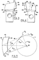
- the angle at which the cutting edge 30 extends relative to the plane P T which is the plane perpendicular to the cutter radius R C1 , is known as the blade angle or pressure angle ⁇ and is shown in Figure 2.
- the plane P S1 that contains the front face 32 and the cutting edge 30 is known as the sharpening plane and the plane P S1 is tangent to a circle, D, having the cutter axis 22 passing through its center.
- the radius R 01 of the circle D is referred to as the offset distance.
- the sharpening plane P S1 is oriented at an angle K with respect to a line R C1 (the cutter radius) extending between the axis 22 and the cutting edge 30 with this angle K being referred to as the offset angle or side rake angle.
- the dotted lines in Figure 5 illustrate the position of a front face 35 (See Figure 4 also) that may exist after several sharpenings of the cutter blade.
- the dotted lines in Figure 5 are shown, for illustrative purposes, to lie in the same plane of rotation as lines R C1 and R 01 . However, in actuality, the dotted lines lie in a lower plane of rotation given the helicoidal form of the cutting blade.
- the cutting edge 30 may be tilted by controlling the orientation of the sharpening plane P S1 with respect to the axis 22.
- the angle of tilt is referred to as the hook angle, designated angle H, and is defined as the angle between an axial plane, P A , (containing the cutter radius, R C1 ) and the cutting edge 30, when projected into a plane perpendicular to the cutter radius, R C1 .
- Figure 6 exemplifies a forward direction of tilt which is referred to as a positive hook angle, however, the front face 32 may be tilted in a rearward direction which is known as a negative hook angle.
- the hook angle H may be controlled by varying the orientation of the sharpening plane P S1 by methods such as those described below.
- Figures 7, 8, 9, and 10 represent prismatic illustrations of an outside cutting blade having a zero hook angle, that is, the cutting edge 30 lies in a plane perpendicular to the cutting direction.
- Figure 7 shows an outside cutter blade having cutting side surface 34 and tip surface 40 projected into a plane, P R (the plane of the page), which is parallel to the plane of cutter rotation and perpendicular to the cutter axis 22.
- P R the plane of the page
- projected cutting edge 30 is coincident with the cutter radius, R C , and therefore lies in the axial plane P A .
- Line 33 is the base of the front face and is also the line of intersection of the sharpening plane P S and the plane P R .
- Offset or side rake angle K is shown extending between the sharpening plane P S (line 33) and the cutter radius coincident with cutting edge 30. See Figure 5 also. It is to be understood that angle K can be defined at any point along the height of the cutting edge 30 and need not be limited to being defined at the base 33. Angle K is the angle between the sharpening plane, P S , at any point along the cutting edge 30, and the cutter radius at that point.
- Figure 8 illustrates a view along line 33 of Figure 7. This figure illustrates angle S which is the angle between the plane P R and the sharpening plane, which contains the front face 32, and is measured in a plane perpendicular to both planes P R and the sharpening plane.
- Figure 9 depicts a side prismatic view of cutting side surface 34 with clearance edge 36 and base line 33 illustrated by the dotted lines.
- Figure 10 is a view of the front face 32 of the cutting blade showing base line 33, clearance edge 36, tip surface 40, and cutting edge 30. Pressure angle ⁇ is shown extending between cutting edge 30 and the plane, P T , which is perpendicular to the cutter radius at the cutting edge 30.
- the hook angle, H (see Figure 6) can be controlled and manipulated by adjusting the position and orientation of the sharpening plane P S which contains the front face 32 of the cutting blade. In turn, a change in the pressure angle ⁇ of the cutting edge 30 accompanies the change in hook angle. Hook angle change is brought about by changing offset angle or side rake angle K, angle S, or a combination thereof.
- Figures 11, 12, 13, and 14 illustrate the preferred procedure for changing the hook angle H by changing the offset angle K and show the accompanying effects of such a change on the pressure angle of the cutting blade.
- the sharpening plane represented by line 33
- R 0 the offset distance
- FIG. 5 the offset distance, R 0 , (See Figure 5) which in effect amounts to pivoting the sharpening plane about the outermost point on the cutting edge 30 designated point Q in Figure 11.
- This movement of the sharpening plane through an angle ⁇ K results in a new offset angle K' being established with respect to the axial plane and initial cutting edge 30 and shifts the cutting edge 30 to a new location 30' as shown in Figure 11.
- Figure 12 is a view taken along line 33' of Figure 11 and illustrates the angular orientation of the cutting edge 30', and hence the sharpening plane, as a result of the angle K change.
- the angle S is held constant during the angle K change and therefore the angular orientation between the sharpening plane and the plane, P R , parallel to the plane of cutter rotation, remains unchanged.
- Figure 13 represents a side view of the cutting blade and shows the effect of the ⁇ K change on the hook angle. It can be seen that the decrease in the angle K, while holding angle S constant, results in a positive change ⁇ H in the hook angle. In other words, repositioning of the sharpening plane as shown in Figure 11 has the effect on the hook angle as illustrated in Figure 13.
- the change in hook angle H is accompanied by a change in the pressure angle ⁇ as shown by Figure 14.
- the position of the front face 32 relative to its position prior to the ⁇ K change is shown by the dotted lines.
- the result of the change in angle K is the effective addition of stock material to the front face of the cutting blade as illustrated by Figure 13.
- adding stock material has the effect of shifting the position of the front face further away from the cutter head and outward with respect to the axis of rotation.
- Figure 14 shows that the cutting edge 30 has shifted outwardly to a new position 30' and tip surface 40 has shifted further away from the cutter head to a new position 40'.
- Figures 15, 16, 17, and 18 illustrate an alternative procedure for controlling the hook angle H and the accompanying effect thereof on the pressure angle ⁇ .
- This procedure involves varying angle S while holding angle K constant.
- Figure 15 shows a prismatic representation of the net effect where angle K is unchanged but the position of the sharpening plane, and hence the front face and cutting edge 30, is reoriented. This is accomplished by adjusting angle S, that is, adjusting the angular orientation of the sharpening plane with respect to a plane, P R , parallel to the plane of cutter rotation.
- This change amounts to pivoting the sharpening plane about line 33 which is at the base of the front face and is also the line of intersection of the sharpening plane with the plane parallel to the plane of rotation of the cutter head.
- Figure 16 is a view taken along line 33 of Figure 15 and illustrates a negative change in angle S.
- the sharpening plane, and therewith the front face and cutting edge 30, is angularly adjusted by an amount ⁇ S thus resulting in a new angle S' and a new position for the cutting edge designated 30'.
- Figures 17 and 18 show that the change in angle S results in a positive change in the hook angle ⁇ H which in turn effectively represents the addition of stock material to the front face of the cutting blade and a shifting of the cutting edge to the location designated 30' and tip surface to the location 40'.
- the net effect on the pressure angle is a negative change ⁇ resulting in a new pressure angle ⁇ '.
- angle S in a manner opposite that discussed above and shown in Figure 16, opposite effects on the hook and pressures angles can be realized.
- Modification of the hook angle H and, therewith, the pressure angle ⁇ may be accomplished by either a change in offset angle K, a change in angle S or a combination thereof.
- the changes discussed above with reference to an outside cutting blade are equally applicable to inside cutting blades.
- Figures 19, 20 and 21 show various hook angle changes and their accompanying effects on the pressure angle of the cutting blades.
- Figure 19 illustrates zero degree hook angle. It can be seen by the dotted lines that as the cutting blade is sharpened back toward the back face 42, the front face 32 maintains the same cross-sectional shape with no pressure angle change and that the front face 32 and the cutting edge 30 move inward and downward relative to its original position. This is a pure radial change and is due to the helicoidal shape of the cutting blade wherein, as previously discussed, the position of the front face 32 moves in a direction toward the front surface 11 of the cutter head 10 as the blade is sharpened. When all blades in a cutter are sharpened back, the front faces 32 of the all blades move toward the front surface 11 of the cutter head 10, however, the relative positions of the blades with respect to one another do not change.
- Figure 20 illustrates a positive hook angle change ⁇ H wherein it is seen that such a modification results in a negative pressure angle change ⁇ .
- the effect is that more stock material is removed toward the base of the cutting face 32.
- the same effect can be realized by adding stock material to the upper portion of the blade as illustrated in Figures 14 and 18 for example.
- the net effect on the cutting face 32 is that the lower portions of the edges 30 and 36 move inward relative to their original positions by an amount proportional to the amount of stock removed by the change in hook angle ⁇ H.
- the greatest amount of stock removed is near the bottom of the blade hence the greatest amount of inward movement of the edges 30 and 36 is also near the bottom of the front face 32.
- Figure 21 illustrates a negative hook angle change ⁇ H which results in a positive pressure angle change ⁇ on the blade front face 32.
- the change in the position of the sharpening plane P S1 is adjusted such that more stock material is removed near the tip 40 of the blade.
- the effect on the front face 32 of the blade being that the edges 30 and 36 move inwardly relative to their original positions with the greatest amount of inward movement being near the tip 40 of the front face 32 which is expected since the greatest amount of stock material was removed near the top of the blade.
- each blade cutting edge can thereby be controlled.
- outside blades for example, if it is discovered that the cutting edge 30 of one blade is located at a greater radial distance from the cutter axis 22 relative to the cutting edges of the remaining blades, sharpening back the entire front face 32 of that one blade by a predetermined amount will result in the entire cutting edge 30 moving inwardly (see Figure 19) and the cutting edge 30 can be correctly repositioned with respect to the remaining blades.
- a cutting blade is positioned in the slot 18 by the use of particular wedges 24 and shims or parallels 26.
- the shims 26 are used to control the radial position of the cutting edge 30 with respect to the axis 22.
- the wedges 24 are used to make very small radial position changes and small angular orientation changes.
- Cutter head 10 includes a slightly tapered edge surface 13.
- Wedge 24 is a tapered element which includes one surface being nominally complementary with edge surface 13 and another surface which is parallel to the cutter axis 22 when the nominally complementary surfaces are placed next to one another. Small radial adjustments of each cutting blade can be achieved by loosening the screw 50 and turning the wedge-adjusting screw 52 (See Figure 2) which is engaged in a recess 54 in the wedge 24.
- wedge-adjusting screw 52 urges the wedge 24 either toward or away from the cutter face 11, depending upon the direction turned, thus causing the radial position of the cutting blade to be varied. Once the desired radial position is achieved, screw 50 is tightened thus maintaining the desired position.
- sharpening of form relieved cutters has involved a uniform removal of stock from the face of each blade.
- the cutter undergoes truing wherein the radial and angular position of each blade is measured and compared to a master blade which is one of the blades located in the cutter head.
- the radial position of each blade is adjusted by the up or down movement of the adjusting wedges.
- the angular orientation of each blade is altered by installing a wedge with a slightly different included angle. This mechanical truing and angling procedure requires great skill and consumes much time.
- the present invention incorporates the truing and angling process into the sharpening process.
- the radial and angular position of each blade is controlled by removal of predetermined amounts of stock material thereby eliminating the tedious and time consuming prior art approach of mechanically adjusting each individual blade.
- the present process is applicable to form-relieved cutters having inside blades, outside blades, both inside and outside blades, and/or other types of form-relieved blades.
- a cutter has groups of like blades, such as both inside and outside blades, all like blades are sharpened in one operation.
- like blades it is meant that all blades of the same form are sharpened together, for example, all inside blades are sharpened together and all outside blades are sharpened together.
- a group of like blades is defined as one or more blades of the same form. The sequence of blades groups to be sharpened does not matter.
- a group of inside blades may be sharpened before the group of outside blades or vice versa.
- a sharpening or grinding machine for carrying out the present inventive process is schematically illustrated by Figure 22.
- a preferred machine for carrying out the present inventive process is one having computer numerical control (CNC), an example of which is described below.
- CNC computer numerical control
- Such machines are well known in the art and are readily available.
- the machine comprises a base 60 upon which a tool carriage 62 is mounted via slides or ways (not shown).
- the tool carriage 62 is movable on the slides along the machine base 60 in a direction Y (Y-axis).
- Located on tool carriage 62 is a tool column 64 to which is mounted tool slide 66, via ways or slides (not shown), for movement in a direction Z (Z-axis) perpendicular to the Y-axis movement of tool carriage 62.
- a tool head 68 is secured to tool slide 66 and an appropriate stock removing tool, such as a grinding wheel 70, is mounted for rotation to the tool head 68.
- the grinding wheel 70 is rotatable about an axis B and is driven by a motor 72 acting through suitable reduction gearing 74.
- first workpiece carriage 80 which is movable along the machine base 60 in a direction X (X-axis) perpendicular to both the Y-axis and Z-axis movements.
- a second workpiece carriage 82 is pivotably mounted to the first workpiece carriage 80 and is pivotable about an axis C.
- workpiece column 84 Secured to the second workpiece carriage 82 is workpiece column 84 in which a spindle (not shown) is journaled for rotation about axis A and is driven by motor 86.
- a cutter 90 is releasably mounted to the spindle for rotation about the A-axis.
- Relative movement of the tool 70 and cutter 90 along each of the mutually perpendicular axes X, Y, and Z is imparted by respective drive motors (not shown) which act through speed reducing gearing and recirculating ball screw drives (not shown). Pivoting of the second workpiece carriage 82 about the C-axis is imparted by a drive motor (not shown) acting through a worm which engages with a worm wheel carried by the pivotable workpiece carriage 82.
- Each of the respective drive motors is associated with either a linear or rotary encoder as part of a CNC system which governs the operation of the drive motors in accordance with input instructions input to a computer.
- the encoders provide feedback information to the computer concerning the actual positions of each of the movable machine axes.
- CNC systems for controlling the movement of multiple machine axes along prescribed paths are now commonplace. Such state-of-the-art systems are incorporated in the present invention to control movements of selected axes along selected paths for sharpening the blades of a form-relieved face mill cutter in accordance with the present inventive process.
- the present inventive process begins by providing an essentially defect-free front face 32 and cutting edge 30 on each blade of a particular blade group, for example, inside blades or outside blades. If the blades are worn from cutting, a uniform amount of stock is removed from the front face 32 of each blade, by grinding for example. However, there are occasions when truing and angling must be checked on a new cutter, such as after shipping and handling, and in this instance a clean front face and cutting edge already exists on the blades and further stock removal is not necessary.
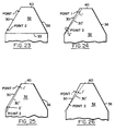
- the cutting edge 30 of each blade from the selected blade group is then probed at a first point (Point 1) near the tip 40 ( Figure 23) by the use of a non-contacting and/or a contacting probe with a non-contacting probe being preferred.
- Point 1 is generally located at about one-third ( 1 / 3 ) of the cutting depth of the cutting blades.
- the purpose of probing at the upper Point 1 is to determine the radial positions of each blade relative to the cutter axis 22 and to one another. After a point near the tip 40 is selected as shown in Figure 23 and a measurement device has been positioned to make measurements at that point, each blade is moved past the measuring device to obtain a position reading of a first point on its cutting edge with all first points lying in the same plane of rotation about the cutter axis.
- the positions of the Point 1 for each blade are stored by the computer.
- the stored points are then compared and the lowest blade is selected.
- the term “lowest blade” it is meant the blade which, for inside blades, has Point 1 and hence the cutting edge located farthest from the cutter axis 22.
- the term “lowest blade” is intended to set forth the blade which has Point 1 and hence the cutting edge closest to the cutter axis 22.
- the lowest blade is selected and designated for reference purposes as the “zero blade” and the relative differences between the position of Point 1 of each remaining blade and the position of Point 1 of the lowest blade are calculated and stored.
- the differences for each blade in a group are all assigned a positive value.
- the difference for each remaining blade is the amount that the cutting edge of each remaining blade must be moved radially with respect to the lowest blade in order that all cutting edges will follow the same path, that is, so that all cutting edges will track one another.
- all blades except the lowest blade and those within acceptable tolerances thereof will require an amount of stock to be removed from their respective front faces in order that the new cutting edge will fall within the accepted tolerances of the lowest blade.
- the calculated difference for each remaining blade is added to the respective original angular sharpening position of each remaining blade and the position of a new Point 1 is obtained and stored for each remaining blade.
- the next step in the present inventive process is probing at a second point (Point 2) on the cutting edge 30 located near the base 33. See Figure 23.
- Point 2 is generally located at about three-fourths (3 ⁇ 4) the cutting depth of the cutting blades.
- the purpose of this step is to check the angular orientation of each cutting edge 30. After a point near the base 33 is selected as shown in Figure 23 and a measurement device has been positioned to make measurements at that point, each blade is moved past the measuring device to obtain a position reading of a second point on its cutting edge with all second points lying in the same plane of rotation about the cutter axis.
- the positions of Point 2 for each blade are stored by the computer.
- the lowest blade with regard to Point 1 is selected as the reference blade and the position of the second point on the cutting edge on this blade is designated for reference purposes as the "zero location".
- the differences between the positions of the second point of the lowest blade and the second point of each of the remaining blades are calculated and stored. Unlike the Point 1 differences wherein all remaining blades are "higher” than the lowest blades, Point 2 differences for the remaining blades may be positioned either positive or negative with respect to Point 2 of the lowest blade. Therefore it is important that positive and negative conventions be assigned and maintained throughout the present inventive process.
- Figures 24 and 25 illustrate examples of new cutting edges 30' based on new points 1' and 2'.
- new points 1' and 2' have been calculated and a new cutting edge 30' based on these new points has been determined.
- the new cutting edge 30' is formed by repositioning the sharpening plane which effects a negative hook angle change ⁇ H, with respect to original cutting edge 30.
- the negative hook angle change is accompanied by a positive pressure angle change ⁇ similar to that shown in Figure 21.
- new points 1' and 2' have been calculated and new cutting edge 30' has been determined.
- Cutting edge 30' is formed by repositioning the sharpening plane for effecting a positive hook angle change ⁇ H, with respect to original cutting edge 30, which is accompanied by a negative pressure angle change ⁇ similar to that shown in Figure 20.
- a cutting blade may not have sufficient stock material with respect to the original cutting surface to allow for formation of the new cutting surface.
- Figures 26, 27, and 28 illustrate examples of new cutting surfaces wherein sufficient stock material is not present to allow for their formation.
- Figure 27 illustrates the opposite situation of Figure 26.
- new Point 2' has been determined and Point 1 is correctly positioned and therefore no new Point 1' is needed.
- additional stock material is needed between Point 1 and the tip 40.
- FIG 29 The solution to the circumstance wherein additional stock is required is illustrated in Figure 29.
- the entire cutter is rotated forward by an amount sufficient to supply adequate stock material for every blade.
- the minimum amount of rotation being such that the blade requiring the greatest amount of additional stock is provided with the required stock.
- rotating the cutter forward causes the cutting edge 30 to effectively move inwardly with respect to the cutter axis.
- Figure 19 shows the inward movement of the cutting edge 30 as the length of an outside blade is traversed. It can be clearly seen that for inside blades, the effect of forward cutter rotation on the cutting edge would result in movement of the cutting edge in a direction opposite that of the outside blades. Namely, the cutting edge of an inside blade would shift outwardly with respect to the cutter axis.
- the amount of material removed from the front faces of the blades should be controlled such that the tips of all blades will essentially lie in a plane of rotation within a tolerance of about 0.002 inches (0.0508 mm). If the tips of one group of blades, either inside or outside for example, are determined to be higher than the tips of the blades in the other group or groups of blades, a uniform amount of stock material is usually removed from the front face of each blade in the higher group thereby lowering the tips (see Figure 19) relative to the blades of the other lower group or groups while maintaining equal spacing between blades of the high group.
- the height of the blades is usually determined by probing, either contacting or non-contacting.
- each blade in a form-relieved face mill cutter can be individually adjusted as a part of the sharpening process without the need to physically reposition each blade by changing or adjusting wedges.
Landscapes
- Engineering & Computer Science (AREA)
- Mechanical Engineering (AREA)
- Human Computer Interaction (AREA)
- Manufacturing & Machinery (AREA)
- Physics & Mathematics (AREA)
- General Physics & Mathematics (AREA)
- Automation & Control Theory (AREA)
- Finish Polishing, Edge Sharpening, And Grinding By Specific Grinding Devices (AREA)
- Grinding-Machine Dressing And Accessory Apparatuses (AREA)
Abstract
Claims (10)
- Procédé pour affûter les lames d'une fraise à lames rapportées (10) de forme dépouillée comportant une pluralité de lames de coupe, chacune desdites lames de coupe présentant un bord de coupe (30), le dressage radial et les positionnements angulaires de chaque bord de coupe précité faisant partie du procédé d'affûtage, ledit procédé comprenant les étapes consistant à :déterminer la position actuelle de chaque bord de coupe précité (30, 30'),comparer ladite position actuelle à une position de référence pour chaque bord de coupe précité,identifier les lames dont les positions actuelles de bord de coupe varient au-delà d'une valeur de tolérance prédéterminée par rapport à ladite position de référence,repositionner le plan d'affûtage (35) de chacune des lames identifiées pour enlever de la matière des lames et placer le bord de coupe de chaque lame identifiée précitée dans une position dans ladite tolérance prédéterminée par rapport à ladite position de référence.
- Procédé selon la revendication 1, où ladite pluralité de lames de coupe, qui sont des lames de coupe intérieures et/ou extérieures, chacune desdites lames comportant une face frontale (32) avec un sommet (40, 40'), une base (33) et deux bords (30, 42), l'un desdits deux bords étant un bord de coupe (30, 30'), avec lesdits bords de coupe (30, 30') s'étendant dudit sommet de ladite face frontale (32) à ladite base (33) de ladite face frontale (32),
où les étapes consistant à déterminer la position de chaque bord de coupe et à comparer la position de chaque bord de coupe a une position de référence comprend les étapes consistant àchoisir lesdites lames de coupe intérieures ou lesdites lames de coupe extérieures,explorer le bord de coupe (30, 30') de chacune des lames choisies à un premier point à proximité dudit sommet de ladite face frontale et stocker l'emplacement dudit premier point de chaque lame précitée,déterminer une lame qui a l'emplacement de premier point le plus bas parmi toutes les lames choisies précitées,calculer une différence de premier point entre ledit emplacement de premier point le plus bas de ladite lame précitée et l'emplacement du premier point sur chacune des lames choisies restantes et stocker chaque différence de premier point précitée pour chacune desdites lames choisies restantes,établir un nouveau emplacement de premier point pour chacune desdites lames choisies restantes par une soustraction de ladite différence de premier point pour chacune desdites lames choisies restantes de l'emplacement respectif dudit premier point pour chacune desdites lames choisies restantes par quoi, pour chacune desdites lames choisies restantes, l'emplacement de chaque premier point précité est sensiblement le même que l'emplacement le plus bas du premier point d'une lame précitée,explorer le bord de coupe (30, 30') de chaque lame choisie précitée à un deuxième point près de ladite base (33) de ladite face frontale (32) et stocker l'emplacement dudit deuxième point de chaque lame identique précitée,comparer l'emplacement dudit deuxième point d'une lame précitée avec l'emplacement du deuxième point de chacune des lames identiques restantes,calculer une différence de deuxième point entre ledit emplacement de deuxième point d'une lame précitée et l'emplacement dudit deuxième point pour chaque lame identique restante,établir un nouveau emplacement de deuxième point pour chacune desdites lames identiques restantes par la soustraction de ladite différence de deuxième point de chacune desdites lames restantes de l'emplacement respectif du deuxième point de chaque lame identique restante précitée,calculer un nouveau bord de coupe (30, 30') pour chacune desdites lames identiques restantes sur la base dudit nouveau premier point et dudit deuxième nouveau point pour chacune desdites lames identiques restantes,repositionner le plan d'affûtage (35) de chacune desdites lames identiques restantes pour former un nouveau bord de coupe (30, 30') sur celui-ci par quoi lesdites premier et deuxième nouveaux points pour chacune desdites lames identiques restantes se situent sur ledit nouveau bord de coupe (30') défini par le plan d'affûtage repositionné (35'). - Procédé selon la revendication 1, où ledit repositionnement dudit plan d'affûtage (35) comprend le changement d'au moins un angle de déport (K) et de l'angle S,
ledit angle (S) étant l'angle entre ledit plan d'affûtage (35) et le plan (PR) mesuré dans un plan perpendiculaire à la fois au plan (PR) et au plan d'affûtage,
ledit plan (PR) étant parallèle au plan de rotation des lames de coupe (22) et perpendiculaire à l'axe de rotation de la fraise,
ledit angle de déport (R) étant l'angle entre le plan d'affûtage (35) à n'importe quel point le long du bord de coupe et une ligne entre l'axe de rotation de la lame (22) et ledit point le long du bord de coupe. - Procédé selon la revendication 1, où ledit repositionnement du plan d'affûtage (35) produit un changement de la position radiale dudit bord de coupe (30, 30').
- Procédé selon l'une des revendications 1 à 4, où ledit repositionnement dudit plan d'affûtage (35) produit un changement de l'angle de pression (φ) dudit bord de coupe,
ledit angle de pression étant l'angle où le bord de coupe (30) s'étend relativement au plan perpendiculaire à un rayon de fraise (RC). - Procédé selon la revendication 2, où ladite exploration est exécutée avec une sonde qui ne vient pas en contact.
- Procédé selon la revendication 2, où pour chaque lame identique restante précitée, au moins un desdites premier nouveau point et deuxième nouveau point n'est pas établi lorsqu'au moins l'une de ladite différence de premier point et de ladite différence de deuxième point respective ne dépassent pas une valeur de tolérance prédéterminée.
- Procédé selon la revendication 2, comportant en outre la répétition dudit procédé pour les autres desdites lames intérieures et desdites lames extérieures.
- Procédé selon la revendication 8, incluant en outre le contrôle de la hauteur relative desdites lames intérieures et desdites lames extérieures respectives.
- Procédé selon la revendication 2, comportant en outre la rotation de ladite fraise suivant une valeur pour fournir un matériau suffisant pour ledit repositionnement dudit plan d'affûtage pour former ledit nouveau bord de coupe.
Applications Claiming Priority (3)
| Application Number | Priority Date | Filing Date | Title |
|---|---|---|---|
| US877910 | 1992-05-01 | ||
| US07/877,910 US5377454A (en) | 1992-05-01 | 1992-05-01 | Method of truing and angling cutter blades by sharpening |
| PCT/US1992/006890 WO1993022101A1 (fr) | 1992-05-01 | 1992-08-14 | Procede de rectification radiale et de positionnement angulaire de lames de fraisage par affutage |
Publications (2)
| Publication Number | Publication Date |
|---|---|
| EP0638012A1 EP0638012A1 (fr) | 1995-02-15 |
| EP0638012B1 true EP0638012B1 (fr) | 1997-10-22 |
Family
ID=25370975
Family Applications (1)
| Application Number | Title | Priority Date | Filing Date |
|---|---|---|---|
| EP92919236A Expired - Lifetime EP0638012B1 (fr) | 1992-05-01 | 1992-08-14 | Procede de rectification radiale et de positionnement angulaire de lames de fraisage par affutage |
Country Status (8)
| Country | Link |
|---|---|
| US (1) | US5377454A (fr) |
| EP (1) | EP0638012B1 (fr) |
| JP (1) | JP2657115B2 (fr) |
| KR (1) | KR0157664B1 (fr) |
| AU (1) | AU663522B2 (fr) |
| CA (1) | CA2134551C (fr) |
| DE (1) | DE69222871T2 (fr) |
| WO (1) | WO1993022101A1 (fr) |
Families Citing this family (10)
| Publication number | Priority date | Publication date | Assignee | Title |
|---|---|---|---|---|
| DE4316514C2 (de) * | 1993-05-18 | 1996-02-08 | Pallmann Kg Maschf | Verfahren und Vorrichtung zum Nachschärfen der Messer von Zerkleinerungsmaschinen |
| AU708931B2 (en) * | 1995-08-31 | 1999-08-19 | Gleason Works, The | Method of and apparatus for truing cutter heads |
| DE19629668C1 (de) * | 1996-07-23 | 1998-01-02 | Pallmann Kg Maschf | Verfahren und Vorrichtung zum Nachschärfen von Messern für Zerkleinerungsmaschinen, insbesondere von Zerspanmessern für Holz |
| DE19718681A1 (de) * | 1997-05-02 | 1998-11-05 | Maier Zerkleinerungstech Gmbh | Messerringzerspaner |
| US6427098B1 (en) | 1999-03-22 | 2002-07-30 | Unova Ip Corp | Method for controlling pivoting machine member |
| US6272962B1 (en) | 1999-08-18 | 2001-08-14 | Uht Corporation | Cutting blade |
| US6811362B2 (en) * | 2000-10-25 | 2004-11-02 | E. W. Tooling, Inc. | Constant dimension insert cutting tool with regrindable profiled inserts |
| US6536313B1 (en) * | 2001-10-01 | 2003-03-25 | General Motors Corporation | Method for making insert for rotary cutter |
| US9481060B2 (en) | 2013-02-05 | 2016-11-01 | Thomas Allen Mullis | Sharpening radial teeth on the surface of a disk |
| DE202016102268U1 (de) * | 2016-02-09 | 2016-05-17 | Atm Gmbh | Trennmaschine |
Family Cites Families (14)
| Publication number | Priority date | Publication date | Assignee | Title |
|---|---|---|---|---|
| US2930112A (en) * | 1957-07-01 | 1960-03-29 | Gleason Works | Adjustable cutter for spiral bevel gears and the like |
| US3192604A (en) * | 1963-08-09 | 1965-07-06 | Gleason Works | Adjustable face mill cutter |
| US3268980A (en) * | 1964-10-16 | 1966-08-30 | Gleason Works | Inserted blade face mill cutter |
| US3817002A (en) * | 1972-06-01 | 1974-06-18 | S Carlson | Automatic indexing head for machining a work piece |
| JPS582008B2 (ja) * | 1977-06-22 | 1983-01-13 | 相浦 正人 | 歯車創成用球形ホブ |
| US4170091A (en) * | 1977-07-05 | 1979-10-09 | The Gleason Works | Apparatus for resharpening cutting blades for gear cutting machine |
| US4341044A (en) * | 1980-05-19 | 1982-07-27 | Mcdonnell Douglas Corporation | Machine for grinding gashes in end mill cutters |
| DE3320042A1 (de) * | 1983-06-03 | 1984-12-13 | Dieter Dr.-Ing. 7505 Ettlingen Wiener | Verfahren zum schleifen vorverzahnter und schleifmaschine zum durchfuehren dieses verfahrens |
| US4760668A (en) * | 1986-07-02 | 1988-08-02 | Alfred Schlaefli | Surface grinding machine and method |
| IT1218510B (it) * | 1987-09-11 | 1990-04-19 | Cima | Apparecchiatura per la diamantatura in macchina delle mole a vite impiegate in macchine rettificatrici di ingranaggi |
| US5020279A (en) * | 1987-12-24 | 1991-06-04 | Saratovskol Spetsialnol Konstruktorskol Bjuro Zuboobrabaty-Vajuschikh Stankov Saratovskogo Stankostro-Itelnogo Proizvodstvennogo Obiedinenia | Machine tool for manufacture and dressing of tools and for finish-machining of gear wheels |
| US4993096A (en) * | 1989-07-31 | 1991-02-19 | D.E.M. Controls Of Canada | Circuit board deburring system |
| US5136522A (en) * | 1990-06-13 | 1992-08-04 | The Gleason Works | Stock dividing method and apparatus for gear manufacturing machine |
| US5138799A (en) * | 1991-04-12 | 1992-08-18 | Bryant Grinder Corporation | Probe positioning mechanism for a radius dresser |
-
1992
- 1992-05-01 US US07/877,910 patent/US5377454A/en not_active Expired - Fee Related
- 1992-08-14 WO PCT/US1992/006890 patent/WO1993022101A1/fr not_active Ceased
- 1992-08-14 KR KR1019940703702A patent/KR0157664B1/ko not_active Expired - Fee Related
- 1992-08-14 AU AU25457/92A patent/AU663522B2/en not_active Ceased
- 1992-08-14 DE DE69222871T patent/DE69222871T2/de not_active Expired - Fee Related
- 1992-08-14 EP EP92919236A patent/EP0638012B1/fr not_active Expired - Lifetime
- 1992-08-14 JP JP5519215A patent/JP2657115B2/ja not_active Expired - Fee Related
- 1992-08-14 CA CA002134551A patent/CA2134551C/fr not_active Expired - Fee Related
Also Published As
| Publication number | Publication date |
|---|---|
| CA2134551C (fr) | 1998-04-28 |
| KR950701263A (ko) | 1995-03-23 |
| DE69222871T2 (de) | 1998-04-02 |
| DE69222871D1 (de) | 1997-11-27 |
| JPH07506059A (ja) | 1995-07-06 |
| AU2545792A (en) | 1993-11-29 |
| WO1993022101A1 (fr) | 1993-11-11 |
| EP0638012A1 (fr) | 1995-02-15 |
| US5377454A (en) | 1995-01-03 |
| CA2134551A1 (fr) | 1993-11-11 |
| JP2657115B2 (ja) | 1997-09-24 |
| AU663522B2 (en) | 1995-10-12 |
| KR0157664B1 (ko) | 1999-01-15 |
Similar Documents
| Publication | Publication Date | Title |
|---|---|---|
| US20250058389A1 (en) | Chamfering tool, chamfering system, gear-cutting machine and method for chamfering toothings | |
| US4186529A (en) | Programmably controlled method for grinding end cutting tools and the like | |
| KR101746078B1 (ko) | 공작기계 및 기어링 제조 방법 | |
| US4329096A (en) | Gear cutter | |
| EP3233344B1 (fr) | Machine et procédé de fabrication et de dressage d'un dispositif de coupe | |
| KR20170037857A (ko) | 기어 블랭크를 디버링하는 방법 | |
| KR19990082006A (ko) | 분할동안에 기어를 가공하는 방법 | |
| US5377454A (en) | Method of truing and angling cutter blades by sharpening | |
| AU6779496A (en) | Method of and apparatus for truing cutter heads | |
| US6311590B1 (en) | Cutting tool for producing gears by face hobbing | |
| EP0706436B1 (fr) | Procede d'affutage de lames de coupe | |
| EP2916986B1 (fr) | Fraise à tailler les roues dentées avec des lames radialement réglables | |
| EP0686075B1 (fr) | Procede d'aiguisage de lames de decoupe aux surfaces profilees-meulees | |
| EP1472048B1 (fr) | Procede de meulage de lames de coupe | |
| CN102059597B (zh) | 一种硬齿面插齿刀负倒棱的加工方法 | |
| US5305558A (en) | Method of sharpening profile-sharpened cutting blades | |
| KR100291166B1 (ko) | 공구이송방법 | |
| Paterson | Control of quality in the manufacture of bevel gears |
Legal Events
| Date | Code | Title | Description |
|---|---|---|---|
| PUAI | Public reference made under article 153(3) epc to a published international application that has entered the european phase |
Free format text: ORIGINAL CODE: 0009012 |
|
| 17P | Request for examination filed |
Effective date: 19941121 |
|
| AK | Designated contracting states |
Kind code of ref document: A1 Designated state(s): AT BE CH DE DK ES FR GB GR IE IT LI LU MC NL SE |
|
| RBV | Designated contracting states (corrected) |
Designated state(s): DE FR GB IT SE |
|
| 17Q | First examination report despatched |
Effective date: 19960409 |
|
| GRAG | Despatch of communication of intention to grant |
Free format text: ORIGINAL CODE: EPIDOS AGRA |
|
| GRAH | Despatch of communication of intention to grant a patent |
Free format text: ORIGINAL CODE: EPIDOS IGRA |
|
| GRAH | Despatch of communication of intention to grant a patent |
Free format text: ORIGINAL CODE: EPIDOS IGRA |
|
| GRAA | (expected) grant |
Free format text: ORIGINAL CODE: 0009210 |
|
| AK | Designated contracting states |
Kind code of ref document: B1 Designated state(s): DE FR GB IT SE |
|
| REF | Corresponds to: |
Ref document number: 69222871 Country of ref document: DE Date of ref document: 19971127 |
|
| ET | Fr: translation filed | ||
| ITF | It: translation for a ep patent filed | ||
| PLBE | No opposition filed within time limit |
Free format text: ORIGINAL CODE: 0009261 |
|
| STAA | Information on the status of an ep patent application or granted ep patent |
Free format text: STATUS: NO OPPOSITION FILED WITHIN TIME LIMIT |
|
| 26N | No opposition filed | ||
| PGFP | Annual fee paid to national office [announced via postgrant information from national office to epo] |
Ref country code: FR Payment date: 19990802 Year of fee payment: 8 |
|
| PGFP | Annual fee paid to national office [announced via postgrant information from national office to epo] |
Ref country code: SE Payment date: 20000802 Year of fee payment: 9 |
|
| PG25 | Lapsed in a contracting state [announced via postgrant information from national office to epo] |
Ref country code: FR Free format text: LAPSE BECAUSE OF NON-PAYMENT OF DUE FEES Effective date: 20010430 |
|
| REG | Reference to a national code |
Ref country code: FR Ref legal event code: ST |
|
| PG25 | Lapsed in a contracting state [announced via postgrant information from national office to epo] |
Ref country code: SE Free format text: LAPSE BECAUSE OF NON-PAYMENT OF DUE FEES Effective date: 20010815 |
|
| REG | Reference to a national code |
Ref country code: GB Ref legal event code: IF02 |
|
| EUG | Se: european patent has lapsed |
Ref document number: 92919236.7 |
|
| PGFP | Annual fee paid to national office [announced via postgrant information from national office to epo] |
Ref country code: GB Payment date: 20040707 Year of fee payment: 13 |
|
| PGFP | Annual fee paid to national office [announced via postgrant information from national office to epo] |
Ref country code: DE Payment date: 20040831 Year of fee payment: 13 |
|
| PG25 | Lapsed in a contracting state [announced via postgrant information from national office to epo] |
Ref country code: IT Free format text: LAPSE BECAUSE OF NON-PAYMENT OF DUE FEES Effective date: 20050814 Ref country code: GB Free format text: LAPSE BECAUSE OF NON-PAYMENT OF DUE FEES Effective date: 20050814 |
|
| PG25 | Lapsed in a contracting state [announced via postgrant information from national office to epo] |
Ref country code: DE Free format text: LAPSE BECAUSE OF NON-PAYMENT OF DUE FEES Effective date: 20060301 |
|
| GBPC | Gb: european patent ceased through non-payment of renewal fee |
Effective date: 20050814 |