EP0638014B1 - Rasierer mit schutzsystem - Google Patents
Rasierer mit schutzsystem Download PDFInfo
- Publication number
- EP0638014B1 EP0638014B1 EP93911755A EP93911755A EP0638014B1 EP 0638014 B1 EP0638014 B1 EP 0638014B1 EP 93911755 A EP93911755 A EP 93911755A EP 93911755 A EP93911755 A EP 93911755A EP 0638014 B1 EP0638014 B1 EP 0638014B1
- Authority
- EP
- European Patent Office
- Prior art keywords
- blade
- cutting edge
- cassette
- edge
- plane
- Prior art date
- Legal status (The legal status is an assumption and is not a legal conclusion. Google has not performed a legal analysis and makes no representation as to the accuracy of the status listed.)
- Expired - Lifetime
Links
- 230000013011 mating Effects 0.000 claims description 27
- 238000010276 construction Methods 0.000 description 5
Images


Classifications
-
- B—PERFORMING OPERATIONS; TRANSPORTING
- B26—HAND CUTTING TOOLS; CUTTING; SEVERING
- B26B—HAND-HELD CUTTING TOOLS NOT OTHERWISE PROVIDED FOR
- B26B21/00—Razors of the open or knife type; Safety razors or other shaving implements of the planing type; Hair-trimming devices involving a razor-blade; Equipment therefor
- B26B21/08—Razors of the open or knife type; Safety razors or other shaving implements of the planing type; Hair-trimming devices involving a razor-blade; Equipment therefor involving changeable blades
- B26B21/14—Safety razors with one or more blades arranged transversely to the handle
- B26B21/22—Safety razors with one or more blades arranged transversely to the handle involving several blades to be used simultaneously
- B26B21/222—Safety razors with one or more blades arranged transversely to the handle involving several blades to be used simultaneously with the blades moulded into, or attached to, a changeable unit
Definitions
- the invention concerns a safety razor according to the preamble of claim 1.
- Such safety razors are known from the descriptions to DK precept No. 144460 and US patent No. 3 786 563.
- This invention serves the purpose of procuring a safety razor of the sort mentioned in the introduction, where the razor blades are provided with a cutting edge on both sides, and a blade cassette, which can be turned inside the cassette holder.
- a blade cassette will last twice as long as that of any conventional safety razor.
- Claim 2 concerns an embodiment of the invention with special locking devices through which the cap section of a blade cassette can be locked to the base section.
- Claim 3 concerns an embodiment of the invention with a special construction of both the blade cassette with exterior mating surfaces and the cassette holder with interior control surfaces, through which a blade cassette can be locked unambiguously in the cassette holder, and
- claim 4 concerns an embodiment of the invention with special devices through which a blade cassette can be locked in position in proportion to the cassette holder.
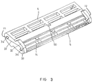
- the safety razor has, as is seen from Fig. 1 a handle 1, which at the top ends in a cassette holder 2 in which a demountable blade cassette has been mounted.
- a blade cassette 3 consists of a cap section 4 and a base section 5. Between the cap section and the base section is a front-lying, elongate razor blade 6 with a forward cutting edge 7; lying behind it and parallel to it is a rear, elongate razor blade 8, which on its front has a cutting edge 9.
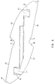
- the blades are mutually spaced by a distance b, which e.g. could be 0.5 mm, by means of a distance piece 10.
- the body part 4 has been designed with a contact face 11, intended to contact the skin during shaving.
- the front edge 12 of the contact face 11 is recessed or drawn back a distance a of e.g. 0.63 mm in comparison to the edge 9 of the blade 8.
- the contact face 11 lies at a lower level than a plane through the cutting edges 7 and 9, and could e.g. form an angle of 23° with the plane of the blade 8.
- the base section 5 protrudes in front of the cutting edge 7 of the blade 6 and has on its front a longitudinal edge or bearer 13, which on top has a wavy contact face 14, which contacts the skin during shaving.
- the contact face 14 lies at a level which is lower than that of a plane through the cutting edges 7 and 9.
- Behind the bearer 13 base section 5 includes a first row of cut-outs 15, and spaced inwardly therefrom a second row of cut-outs 16.
- the cut-outs 15 and 16 are separated by a longitudinal edge 17 and the cut-outs 15,16 are separated in a crosswise direction by edges 18.
- the cutting edges 7,9 of blades 6, and 8 are mutually spaced apart by a distance c, of e.g. 1.0 mm.
- the distance d between the edge 7 and the first wave of the contact face 14 is e.g. 1.20 mm.
- the blades 6 and 8 lie at an angle v, e.g. of 31°, with a plane through the edged 7 and the top of the first wave of the contact face 14.
- the cassette holder 2 can be placed relative to the handle 1 and the blade cassette 3 can be placed relative to the cassette holder 2 so that the blades 6 and 8 and the handle form an angle of e.g. 65°.
- Behind the edge 7 blade 8 includes a row of cut-outs 21, which - when mounted in the blade cassette 3 - are level with the second row of cut-outs of the base section 5 and thus allow scraps from shaving from the cutting edge 9 to pass. Scraps from shaving from the front edge 7 pass through the first row of cut-outs 15 of the base section 5.
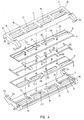
- the blades 6,7 Connected to each cut-out 21 the blades 6,7 include an extra, short cut-out 22 into each of which a dowel 23 with a cross-sectional shape identical to the cut-out 22 can be adapted. These dowels are placed on the longitudinal edges 17.
- the construction includes e.g. two dowels 24 and two holes 25.
- the cap section 4 includes holes 25 level with the dowels 24 and dowels 24 level with the holes 25.
- the blades 6 and 8 and the distance piece 10 include holes 26 and 27, respectively, through which the dowels 24 pass during assembly of the blade casette.
- the cap section 4, the blade 8, the distance piece 10, the blade 6 and the base section 5 are directed into a precise mutual position by the dowels 24 during the assembly of the cassette.
- the blade 6 is on its long side opposite edge 7 provided with another edge 19, and the blade 8 is on the side opposite to the edge 9 provided with another edge 20.
- the distance piece 10 has, level with the edges 28 between the cut-outs 21 of the blades 6 and 8, fingers 29 each having an upper contact face 30 to the blade 8 and a lower contact face 31 to the blade 6.
- the contact faces 11' and 14' belonging to the cutting edges 19 and 20 have been designed as and placed with the same angles as exist between the contact faces 11 and 14 and the blades 6 and 8.
- the cut-outs 15' and 16' are constructed as the cut-outs 15 and 16, and they have been placed in the same mutual position to the edges 19 and 20 as exist between the cut-outs 15 and 16 and the edges 7 and 9. Furthermore the distances a, c and d are identical to both sets of edges.
- the two blades 6 and 8 may be of uniform design, and the blade 8 may then be mounted in the blade cassette in a turned position of 180° relative to the blade 6.
- the cap section 4 may be designed as the base section 5, but it is then mounted in the blade cassette 3 in a turned position of 180° relative to the base section 5.
- the base section 5 and the cap section 4 have at both ends an end piece 32.
- Each end piece has, on the side which faces an adjacent end piece inside the assembled blade cassette, a mating surface 33.
- Each end piece also has at one end a protrusion 34 and at the other end a cut-out or a recess 35.
- the two protrusions 34 of the cap section 4 may mesh in a self-locking grip with the two cut-outs 35 of the base section 5, and the two protrusions 34 of the base section 5 grip with the two cut-outs 35 of the cap section, in which position the two mating surfaces 33 of each end piece 32 will meet.
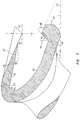
- the blade cassette 3 has been constructed with mating surfaces, and the cassette holder has been provided with interior control surfaces constructed to maintain the cassette holder 3 in a specific, definite first position as well as in an alternate position where it is turned 180° around a central axis in the cassette, whereby the blade 6 and 8 form the same angle with the handle as in the first position.
- the mentioned mating surfaces may consist of the first mating surface 36 stretching from the lower edge 37 of the bearer 13 to for instance the rear edge 38 of the cut-out 16 from where the surface 36 continues to the contact face 11 and from there to the centre line C-C. After that the mating surface continues into surface 39 and another surface 40 both of which are shaped into end pieces 32. Similar mating surfaces are found on the top side of the cap section 4. The frontside of the bearer 13 has been provided with an additional mating surface 41.
- the cassette holder has both an interior, upper control surface 42, which matches the mating surface 36, and a lower control surface 43, which matches the mating surfaces 40 of the two end pieces 32. At its front the control surface 43 continues into a front control surface 44, which matches the mating surface 39, and at the back it continues into a rear control surface 45, which matches the mating surface 41.
- the fronts of the bottom portion 46 and the top portion 47 of the cassette holder terminate by the rear edge 38 of the cut-outs 16 in the base section 5 and the cap section 4, respectively, of a blade cassette 3 mounted in the cassette holder 2.
- the top portion 47 ends in a front tip, and the top side 48 of the top portion is even with and has the same gradient as the contact face 11.
- the bottom portion 46 may be provided with a protrusion 49, which meshes with a hole 50 of the base section 5 or of the cap section 4 and locks the blade cassette 3 into its position.
- the safety razor which has been shown and described is only one example of the invention. Other designs and constructions may be developed within the limits of the invention. The mating surfaces as well as the control surfaces may be elaborated differently.
Landscapes
- Life Sciences & Earth Sciences (AREA)
- Forests & Forestry (AREA)
- Engineering & Computer Science (AREA)
- Mechanical Engineering (AREA)
- Knives (AREA)
- Dry Shavers And Clippers (AREA)
- Packaging Of Annular Or Rod-Shaped Articles, Wearing Apparel, Cassettes, Or The Like (AREA)
- Laser Surgery Devices (AREA)
Claims (4)
- Sicherheitsrasierer, umfassend:- einen an einem Handgriff (1) angebrachten Kassettenhalter (2) mit einem unteren Stück (46) und einem oberen Stück (47) sowie- eine herausnehmbar in den Kassettenhalter (2) eingesetzte Klingenkassette (3),welche Klingenkassette eine obere Kappensektion (4) und eine untere Basissektion (5) umfaßt, zwischen denen eine obere hintere Klinge (8) und parallel dazu eine untere vordere Klinge (6) in einem gegenseitigen Klingenabstand (b), der durch ein Distanzstück (10) zwischen den Klingen festgelegt ist, fest bzw. sicher montiert sind, wobei die vordere Klinge (6) und die hintere Klinge (8) jeweils eine nach vorn weisende erste Schneidkante (7, 9) aufweisen, die erste Schneidkante (9) der hinteren Klinge (8) rückwärts der ersten Schneidkante (7) der vorderen Klinge (6) angeordnet ist, die ersten Schneidkanten (7, 9) eine erste Ebene definieren, während sie in dieser Ebene in einem Schneidkantenabstand (c) beabstandet sind, die Kappensektion (4) eine Vorderkante (12) in einem Abstand (a) rückwärts der ersten Schneidkante (9) der hinteren Klinge (8) und eine Hautkontaktfläche (11) rückwärts ihrer Vorderkante (12) aufweist, die Kontaktfläche (11) gegenüber der ersten Ebene rückwärts versetzt ist, die Basissektion (5) nach vorn über die erste Schneidkante (7) der vorderen Klinge (6) hinausragt und eine längsverlaufende Auflage (13) an ihrer Vorderseite aufweist, die Auflage (13) eine gegenüber der ersten Ebene rückwärts versetzte wellige obere Kontaktfläche (14) aufweist, eine zweite Ebene durch eine Ebene definiert ist, welche die erste Schneidkante (7) der vorderen Klinge (6) umfaßt und eine erste Wellung der welligen Kontaktfläche (14) tangiert, ein Kontaktflächen/-Schneidkanten-Abstand (d) in der zweiten Ebene zwischen der ersten Wellung und der ersten Schneidkante (7) der vorderen Klinge (6) festgelegt ist und ein Schneidkanten/Kontaktflächen-Winkel (v) zwischen der zweiten Ebene und einer die vordere Klinge (6) umfassenden bzw. einschließenden Ebene gebildet ist, wobei die Basissektion (5) eine erste Reihe von rückwärts von der Auflage (13) und vorderhalb der vorderen Klinge (6) vorgesehenen Ausschnitten (15) sowie eine zweite Reihe von unter der vorderen Klinge (6) vorgesehenen Ausschnitten aufweist,
dadurch gekennzeichnet, daß
die vordere Klinge (6) eine zweite Schneidkante (19) an der ihrer ersten Schneidkante (7) gegenüberliegenden Seite und die hintere Klinge (8) und zweite Schneidkante (20) an der ihrer ersten Schneidkante (9) gegenüberliegenden Seite aufweisen, eine Symmetrielinie (O) parallel zu den Schneidkanten der vorderen und hinteren Klingen (6, 8) definiert ist, die Symmetrielinie (O) zentral zwischen der zweiten Schneidkante (20) der hinteren Klinge (8) sowie der ersten Schneidkante (7) der vorderen Klinge (6) und zentral zwischen der zweiten Schneidkante (19) der vorderen Klinge (6) sowie der ersten Schneidkante (9) der hinteren Klinge (8) liegt, die Klingenkassette (3) um die Symmetrielinie (O) vollkommen symmetrisch ist, mit Ausnahme von zwei Paßstiften (24), die von der Basissektion (5) an dem der Auflage (13) gegenüberliegenden Ende nach oben ragen, die Paßstifte (24) jeweils in eine entsprechende Bohrung (25) in der Kappensektion (4) eingepaßt sind und zwei weitere Paßstifte (24) von der Kappensektion (4) an der der Auflage (13') gegenüberliegenden Seite nach unten ragen, die weiteren Paßstifte (24) jeweils in eine entsprechende Bohrung (25) in der Basissektion (5) eingepaßt sind, jeder der Paßstifte (24) und der weiteren Paßstifte (24) jeweils entsprechende (zugeordnete) Bohrungen (26,27) in der vorderen Klinge (6), im Distanzstück (10) und in der hinteren Klinge (8) durchsetzt, die Mittellinien der Paßstifte (24) und der Bohrungen (25, 26, 27) in einer Ebene liegen, die senkrecht zur Ebene der vorderen und hinteren Klingen (6, 8) liegt und die Symmetrielinie (O) umfaßt bzw. einschließt,
die Klingenkassette (3) mit um die Symmetrielinie (O) symmetrischen äußeren Paßflächen versehen ist und der Kassettenhalter (2) mit inneren Steuerflächen versehen ist, damit die Klingenkassette (3) in einer ersten Arretierstellung oder, wenn sie um 180° um die Symmetrielinie (O) gedreht ist, in einer zweiten Arretierstellung gehalten werden kann. - Sicherheitsrasierer nach Anspruch 1, wobei die Basissektion (5) und die Kappensektion (4) jeweils ein Endstück (32) aufweisen,
die Endstücke jeweils eine Paßfläche (33) aufweisen, die einen Vorsprung (34) am einen Ende und einen Ausschnitt oder eine Aussparung (35) am anderen Ende enthält, und
die Vorsprünge und Ausschnitte oder Aussparungen so ausgestaltet und angeordnet sind, daß die Vorsprünge (34) mit selbstsicherndem Griff mit den Ausschnitten oder Aussparungen zusammengreifen, derart, daß die Paßfläche der Kappensektion (4) an der Paßfläche der Basissektion anliegt. - Sicherheitsrasierer nach Anspruch 1, wobei die Unterseite der Basissektion (5) mindestens eine der äußeren Paßflächen (36) umfaßt, welche äußeren Paßflächen von der Unterkante der Auflage (13) zur Hinterkante (38) der Ausschnitte (16) und, über eine Kontaktfläche (11), bis nahe zur Schneidkante (19) verlaufen,
wobei die äußere Paßfläche (36) ferner eine erste ebene (even) Paßfläche (39) und eine zweite Paßfläche (40) an der Unterseite der Endstücke (32) der Kappensektion (4) aufweist,
der Kassettenhalter (2) eine innere Steuerfläche (42) und eine untere Steuerfläche (43), welche mit einer äußeren Paßfläche (36) der Kappensektion bzw. der äußeren Paßfläche der Basissektion übereinstimmen, sowie eine vorn gelegene Steuerfläche (44) und eine hintere Steuerfläche (45) aufweist, welche mit der ersten Paßfläche (39) des Kappensektion-Endstücks bzw. einer Paßfläche an der Vorderseite der Auflage (41) übereinstimmen,
wobei die Klingenkassette in den Kassettenhalter einsetzbar ist und Mittel zum Arretieren der Klingenkassette in ihrer Lage im Klingenhalter verfügbar bzw. vorgesehen sind und
wobei ein unterer Abschnitt (46) und ein oberer Abschnitt (47) des Kassettenhalters nicht weiter vorstehen als die Hinterkante (38) der Ausschnitte (16) in der Basissektion (5) bzw. der Kappensektion (4) des Klingenhalters (3). - Sicherheitsrasierer nach Anspruch 3, wobei der untere Abschnitt (46) des Kassettenhalters (2) einen Vorsprung (49) aufweist und wobei der Vorsprung mit einer Bohrung (50) zusammenzugreifen vermag, die in entweder der Basissektion (5) oder der Kappensektion (4) angeordnet ist.
Applications Claiming Priority (3)
| Application Number | Priority Date | Filing Date | Title |
|---|---|---|---|
| DK538/92 | 1992-04-27 | ||
| DK053892A DK168549B1 (da) | 1992-04-27 | 1992-04-27 | Barbermaskine |
| PCT/DK1993/000137 WO1993022112A1 (en) | 1992-04-27 | 1993-04-23 | Safety razor |
Publications (2)
| Publication Number | Publication Date |
|---|---|
| EP0638014A1 EP0638014A1 (de) | 1995-02-15 |
| EP0638014B1 true EP0638014B1 (de) | 1997-06-18 |
Family
ID=8094677
Family Applications (1)
| Application Number | Title | Priority Date | Filing Date |
|---|---|---|---|
| EP93911755A Expired - Lifetime EP0638014B1 (de) | 1992-04-27 | 1993-04-23 | Rasierer mit schutzsystem |
Country Status (9)
| Country | Link |
|---|---|
| US (1) | US5575068A (de) |
| EP (1) | EP0638014B1 (de) |
| JP (1) | JP3308536B2 (de) |
| AU (1) | AU668960B2 (de) |
| CA (1) | CA2133819A1 (de) |
| DE (1) | DE69311718T2 (de) |
| DK (1) | DK168549B1 (de) |
| ES (1) | ES2105266T3 (de) |
| WO (1) | WO1993022112A1 (de) |
Cited By (1)
| Publication number | Priority date | Publication date | Assignee | Title |
|---|---|---|---|---|
| WO2008023210A1 (en) * | 2006-08-25 | 2008-02-28 | Bic-Violex Sa | Shaving blade unit and shaver having such a blade unit |
Families Citing this family (53)
| Publication number | Priority date | Publication date | Assignee | Title |
|---|---|---|---|---|
| US6473970B1 (en) * | 1997-10-20 | 2002-11-05 | American Safety Razor Company | Razor blade cartridge with lubricating flow paths |
| US6276062B1 (en) * | 1998-04-01 | 2001-08-21 | American Safety Razor Corporation | Triple blade safety razor |
| US6378211B1 (en) * | 1998-04-14 | 2002-04-30 | American Safety Razor Company | Razor blade cartridge with guard ribs |
| US6568084B2 (en) * | 1998-04-14 | 2003-05-27 | American Safety Razor Company | Razor blade cartridge with guard ribs |
| JP3455143B2 (ja) * | 1999-08-30 | 2003-10-14 | 株式会社貝印刃物開発センター | 安全かみそり |
| USD490569S1 (en) | 2001-12-06 | 2004-05-25 | American Safety Razor Company | Razor cartridge overcap |
| GB2406537B (en) | 2003-07-21 | 2006-09-06 | Gillette Co | Safety razors |
| US7617607B2 (en) | 2003-07-21 | 2009-11-17 | The Gillette Company | Shaving razors and other hair cutting assemblies |
| US20050022386A1 (en) * | 2003-07-29 | 2005-02-03 | Macove James A. | Razor having separate blade groups for shaving and trimming/sculpting |
| US7168173B2 (en) | 2004-03-11 | 2007-01-30 | The Gillette Company | Shaving system |
| US7131202B2 (en) | 2004-03-11 | 2006-11-07 | The Gillette Company | Cutting members for shaving razors with multiple blades |
| US7669335B2 (en) | 2004-03-11 | 2010-03-02 | The Gillette Company | Shaving razors and shaving cartridges |
| US7690122B2 (en) | 2004-03-11 | 2010-04-06 | The Gillette Company | Shaving razor with button |
| US7197825B2 (en) | 2004-03-11 | 2007-04-03 | The Gillette Company | Razors and shaving cartridges with guard |
| US8104184B2 (en) | 2004-03-11 | 2012-01-31 | The Gillette Company | Shaving cartridges and razors |
| US20070245564A1 (en) * | 2006-02-09 | 2007-10-25 | Francis Yiu | Shaver with rolling multi-cartridge head |
| CA2738511A1 (en) * | 2008-09-25 | 2010-04-01 | American Safety Razor Company | Trimmer for shaving razor |
| JP4676003B2 (ja) * | 2009-01-06 | 2011-04-27 | 孝 林 | 安全カミソリ |
| USD616148S1 (en) | 2009-05-21 | 2010-05-18 | American Safety Razor | Razor protector |
| USD619300S1 (en) | 2009-05-21 | 2010-07-06 | Ubs Ag, Stamford Branch | Razor protector |
| USD616149S1 (en) | 2009-09-28 | 2010-05-18 | American Safety Razor | Razor cartridge protector |
| USD625883S1 (en) | 2009-11-30 | 2010-10-19 | American Safety Razor | Razor cartridge |
| USD629969S1 (en) | 2010-05-11 | 2010-12-28 | American Safety Razor | Razor cartridge protector |
| USD633253S1 (en) | 2010-06-23 | 2011-02-22 | American Safety Razor | Razor cartridge |
| USD640415S1 (en) | 2010-07-07 | 2011-06-21 | American Safety Razor | Razor cartridge |
| USD648075S1 (en) | 2010-07-07 | 2011-11-01 | American Safety Razor | Razor cartridge |
| USD643976S1 (en) | 2010-10-19 | 2011-08-23 | American Safety Razor | Razor cartridge |
| USD643977S1 (en) | 2010-10-19 | 2011-08-23 | American Safety Razor | Razor cartridge |
| RU2684467C2 (ru) * | 2014-03-05 | 2019-04-09 | Мак-Рай, Инк. | Двусторонняя бритва |
| USD850721S1 (en) * | 2014-03-05 | 2019-06-04 | Mack-Ray, Inc. | Razor cartridge |
| US9550303B2 (en) | 2014-10-07 | 2017-01-24 | Ruairidh Robertson | Shaving device |
| US10112313B2 (en) | 2014-10-07 | 2018-10-30 | Ruairidh Robertson | Shaving device |
| US11014255B2 (en) | 2014-10-07 | 2021-05-25 | Ruairidh Robertson | Shaving device |
| US9764487B2 (en) | 2014-10-07 | 2017-09-19 | Ruairidh Robertson | Shaving device |
| DK3250350T3 (da) | 2015-02-01 | 2021-01-18 | Mack Ray Inc | Dobbeltsidet barbermaskine |
| CN108290304B (zh) * | 2015-12-01 | 2021-03-09 | 比克-维尔莱克 | 剃须刀和剃须刀架 |
| US10946540B2 (en) | 2015-12-01 | 2021-03-16 | Bic-Violex Sa | Shaving razors and shaving cartridges |
| PL3576910T3 (pl) * | 2017-02-02 | 2021-10-04 | Bic Violex S.A. | Wkład golący |
| CN111801205B (zh) | 2018-03-30 | 2022-08-23 | 吉列有限责任公司 | 具有枢转部分的剃刀柄部 |
| WO2019191231A1 (en) | 2018-03-30 | 2019-10-03 | The Gillette Company Llc | Razor handle with a pivoting portion |
| CN111819044B (zh) | 2018-03-30 | 2022-09-16 | 吉列有限责任公司 | 具有枢转部分的剃刀柄部 |
| CA3092881A1 (en) | 2018-03-30 | 2019-10-03 | The Gillette Company Llc | Razor handle with movable members |
| JP2021516135A (ja) | 2018-03-30 | 2021-07-01 | ザ ジレット カンパニー リミテッド ライアビリティ カンパニーThe Gillette Company Llc | 可動部材を有するかみそりハンドル |
| USD874061S1 (en) | 2018-03-30 | 2020-01-28 | The Gillette Company Llc | Shaving razor cartridge |
| US11607820B2 (en) | 2018-03-30 | 2023-03-21 | The Gillette Company Llc | Razor handle with movable members |
| JP2021516136A (ja) | 2018-03-30 | 2021-07-01 | ザ ジレット カンパニー リミテッド ライアビリティ カンパニーThe Gillette Company Llc | 可動部材を有するかみそりハンドル |
| US11571828B2 (en) | 2018-03-30 | 2023-02-07 | The Gillette Company Llc | Shaving razor handle |
| EP3774214B1 (de) | 2018-03-30 | 2023-11-15 | The Gillette Company LLC | Rasierersystem |
| EP3774218A1 (de) | 2018-03-30 | 2021-02-17 | The Gillette Company LLC | Rasierergriff mit einem schwenkbaren abschnitt |
| JP2021516102A (ja) | 2018-03-30 | 2021-07-01 | ザ ジレット カンパニー リミテッド ライアビリティ カンパニーThe Gillette Company Llc | 枢動部分を有するかみそりハンドル |
| EP3774235B1 (de) | 2018-03-30 | 2024-08-21 | The Gillette Company LLC | Rasierergriff mit einem schwenkbaren abschnitt |
| EP3708314B1 (de) * | 2018-03-30 | 2021-12-15 | The Gillette Company LLC | Rasiererhandgriff |
| US11123888B2 (en) | 2018-03-30 | 2021-09-21 | The Gillette Company Llc | Razor handle with a pivoting portion |
Family Cites Families (10)
| Publication number | Priority date | Publication date | Assignee | Title |
|---|---|---|---|---|
| US378658A (en) * | 1887-09-12 | 1888-02-28 | J Fairfield Carpenter | Valve for electro-pneumatic railroad-brakes |
| US3832774A (en) * | 1971-03-15 | 1974-09-03 | Gillette Co | Razor blade assembly |
| US3786563A (en) * | 1971-08-31 | 1974-01-22 | Gillette Co | Shaving system |
| US3783510A (en) * | 1971-10-22 | 1974-01-08 | Warner Lambert Co | Razor having tandemly mounted blades bonded in a disposable cartridge |
| US3777396A (en) * | 1972-06-01 | 1973-12-11 | Warner Lambert Co | Cartridges having tandemly mounted cutting edges on two sides thereof |
| US3892036A (en) * | 1973-06-04 | 1975-07-01 | Gillette Co | Safety razor |
| US4275498A (en) * | 1979-12-31 | 1981-06-30 | Warner-Lambert Company | Safety razor blade cartridge |
| US4407067A (en) * | 1980-10-06 | 1983-10-04 | The Gillette Company | Shaving implement |
| US4980974A (en) * | 1989-05-11 | 1991-01-01 | Radcliffe Allan F | Contoured shaving blades |
| US5133131A (en) * | 1991-08-05 | 1992-07-28 | Hoffman Ralph H | Replaceable double-sided razor blade unit |
-
1992
- 1992-04-27 DK DK053892A patent/DK168549B1/da not_active IP Right Cessation
-
1993
- 1993-04-23 WO PCT/DK1993/000137 patent/WO1993022112A1/en not_active Ceased
- 1993-04-23 JP JP51884693A patent/JP3308536B2/ja not_active Expired - Fee Related
- 1993-04-23 AU AU42602/93A patent/AU668960B2/en not_active Ceased
- 1993-04-23 DE DE69311718T patent/DE69311718T2/de not_active Expired - Fee Related
- 1993-04-23 EP EP93911755A patent/EP0638014B1/de not_active Expired - Lifetime
- 1993-04-23 ES ES93911755T patent/ES2105266T3/es not_active Expired - Lifetime
- 1993-04-23 CA CA002133819A patent/CA2133819A1/en not_active Abandoned
- 1993-04-23 US US08/313,140 patent/US5575068A/en not_active Expired - Fee Related
Cited By (5)
| Publication number | Priority date | Publication date | Assignee | Title |
|---|---|---|---|---|
| WO2008023210A1 (en) * | 2006-08-25 | 2008-02-28 | Bic-Violex Sa | Shaving blade unit and shaver having such a blade unit |
| CN101528426B (zh) * | 2006-08-25 | 2012-06-27 | 比克-维尔莱克 | 剃须刀片组合及包含该刀片组合的剃须刀 |
| US8499459B2 (en) | 2006-08-25 | 2013-08-06 | Bic-Violex Sa | Shaving blade unit and shaver having such a blade unit |
| US8991058B2 (en) | 2006-08-25 | 2015-03-31 | Bic Violex | Shaving blade unit and shaver having such a blade unit |
| US9032627B2 (en) | 2006-08-25 | 2015-05-19 | Bic-Violex Sa | Shaving blade unit and shaver having such a blade unit |
Also Published As
| Publication number | Publication date |
|---|---|
| ES2105266T3 (es) | 1997-10-16 |
| AU668960B2 (en) | 1996-05-23 |
| DE69311718D1 (de) | 1997-07-24 |
| JP3308536B2 (ja) | 2002-07-29 |
| EP0638014A1 (de) | 1995-02-15 |
| WO1993022112A1 (en) | 1993-11-11 |
| DK168549B1 (da) | 1994-04-18 |
| CA2133819A1 (en) | 1993-11-11 |
| JPH07506503A (ja) | 1995-07-20 |
| DK53892A (da) | 1993-10-28 |
| DE69311718T2 (de) | 1997-12-18 |
| AU4260293A (en) | 1993-11-29 |
| US5575068A (en) | 1996-11-19 |
| DK53892D0 (da) | 1992-04-27 |
Similar Documents
| Publication | Publication Date | Title |
|---|---|---|
| EP0638014B1 (de) | Rasierer mit schutzsystem | |
| US7610683B2 (en) | Oval frame razor | |
| US5528832A (en) | Scraper | |
| EP1226904B2 (de) | Rasiersystem | |
| CA2292022C (en) | Razors | |
| US5526567A (en) | Shaving system | |
| EP1963059B1 (de) | Schwenkachse für eine rasiereinheit | |
| US4308663A (en) | Razor handle with latch for pivotable cartridge | |
| US4257160A (en) | Two-bladed safety razor | |
| WO1997017174A2 (en) | Oval frame razor | |
| US4903405A (en) | Safety razors | |
| NL8006551A (nl) | Handvat voor een scheerapparaat. | |
| EP0284194A1 (de) | Scherkopf | |
| JPS5812710Y2 (ja) | 二枚刃安全かみそり | |
| IE52777B1 (en) | Razors and shaving units for razors | |
| JPH0346711Y2 (de) | ||
| HK1064984A (en) | Shaving system and method | |
| HK1048087C (en) | Shaving razor handle | |
| CS251058B2 (cs) | Nosič čepelek | |
| HK1032558B (en) | Shaving razor handle | |
| HK1032559B (en) | Shaving system and method |
Legal Events
| Date | Code | Title | Description |
|---|---|---|---|
| PUAI | Public reference made under article 153(3) epc to a published international application that has entered the european phase |
Free format text: ORIGINAL CODE: 0009012 |
|
| 17P | Request for examination filed |
Effective date: 19941021 |
|
| AK | Designated contracting states |
Kind code of ref document: A1 Designated state(s): BE DE ES FR GB NL PT SE |
|
| 17Q | First examination report despatched |
Effective date: 19960116 |
|
| GRAG | Despatch of communication of intention to grant |
Free format text: ORIGINAL CODE: EPIDOS AGRA |
|
| GRAH | Despatch of communication of intention to grant a patent |
Free format text: ORIGINAL CODE: EPIDOS IGRA |
|
| GRAH | Despatch of communication of intention to grant a patent |
Free format text: ORIGINAL CODE: EPIDOS IGRA |
|
| GRAA | (expected) grant |
Free format text: ORIGINAL CODE: 0009210 |
|
| AK | Designated contracting states |
Kind code of ref document: B1 Designated state(s): BE DE ES FR GB NL PT SE |
|
| REF | Corresponds to: |
Ref document number: 69311718 Country of ref document: DE Date of ref document: 19970724 |
|
| ET | Fr: translation filed | ||
| REG | Reference to a national code |
Ref country code: ES Ref legal event code: FG2A Ref document number: 2105266 Country of ref document: ES Kind code of ref document: T3 |
|
| REG | Reference to a national code |
Ref country code: PT Ref legal event code: SC4A Free format text: AVAILABILITY OF NATIONAL TRANSLATION Effective date: 19970721 |
|
| PLBE | No opposition filed within time limit |
Free format text: ORIGINAL CODE: 0009261 |
|
| STAA | Information on the status of an ep patent application or granted ep patent |
Free format text: STATUS: NO OPPOSITION FILED WITHIN TIME LIMIT |
|
| 26N | No opposition filed | ||
| REG | Reference to a national code |
Ref country code: GB Ref legal event code: IF02 |
|
| PGFP | Annual fee paid to national office [announced via postgrant information from national office to epo] |
Ref country code: GB Payment date: 20030313 Year of fee payment: 11 |
|
| PGFP | Annual fee paid to national office [announced via postgrant information from national office to epo] |
Ref country code: NL Payment date: 20030318 Year of fee payment: 11 |
|
| PGFP | Annual fee paid to national office [announced via postgrant information from national office to epo] |
Ref country code: PT Payment date: 20030402 Year of fee payment: 11 |
|
| PGFP | Annual fee paid to national office [announced via postgrant information from national office to epo] |
Ref country code: FR Payment date: 20030403 Year of fee payment: 11 |
|
| PGFP | Annual fee paid to national office [announced via postgrant information from national office to epo] |
Ref country code: SE Payment date: 20030407 Year of fee payment: 11 |
|
| PGFP | Annual fee paid to national office [announced via postgrant information from national office to epo] |
Ref country code: ES Payment date: 20030428 Year of fee payment: 11 |
|
| PGFP | Annual fee paid to national office [announced via postgrant information from national office to epo] |
Ref country code: DE Payment date: 20030430 Year of fee payment: 11 |
|
| PGFP | Annual fee paid to national office [announced via postgrant information from national office to epo] |
Ref country code: BE Payment date: 20030514 Year of fee payment: 11 |
|
| PG25 | Lapsed in a contracting state [announced via postgrant information from national office to epo] |
Ref country code: GB Free format text: LAPSE BECAUSE OF NON-PAYMENT OF DUE FEES Effective date: 20040423 |
|
| PG25 | Lapsed in a contracting state [announced via postgrant information from national office to epo] |
Ref country code: SE Free format text: LAPSE BECAUSE OF NON-PAYMENT OF DUE FEES Effective date: 20040424 Ref country code: ES Free format text: LAPSE BECAUSE OF NON-PAYMENT OF DUE FEES Effective date: 20040424 |
|
| PG25 | Lapsed in a contracting state [announced via postgrant information from national office to epo] |
Ref country code: BE Free format text: LAPSE BECAUSE OF NON-PAYMENT OF DUE FEES Effective date: 20040430 |
|
| PG25 | Lapsed in a contracting state [announced via postgrant information from national office to epo] |
Ref country code: PT Free format text: LAPSE BECAUSE OF NON-PAYMENT OF DUE FEES Effective date: 20041025 |
|
| BERE | Be: lapsed |
Owner name: *WARNER-LAMBERT CY Effective date: 20040430 |
|
| PG25 | Lapsed in a contracting state [announced via postgrant information from national office to epo] |
Ref country code: NL Free format text: LAPSE BECAUSE OF NON-PAYMENT OF DUE FEES Effective date: 20041101 |
|
| PG25 | Lapsed in a contracting state [announced via postgrant information from national office to epo] |
Ref country code: DE Free format text: LAPSE BECAUSE OF NON-PAYMENT OF DUE FEES Effective date: 20041103 |
|
| EUG | Se: european patent has lapsed | ||
| GBPC | Gb: european patent ceased through non-payment of renewal fee |
Effective date: 20040423 |
|
| PG25 | Lapsed in a contracting state [announced via postgrant information from national office to epo] |
Ref country code: FR Free format text: LAPSE BECAUSE OF NON-PAYMENT OF DUE FEES Effective date: 20041231 |
|
| REG | Reference to a national code |
Ref country code: PT Ref legal event code: MM4A Free format text: LAPSE DUE TO NON-PAYMENT OF FEES Effective date: 20041025 |
|
| NLV4 | Nl: lapsed or anulled due to non-payment of the annual fee |
Effective date: 20041101 |
|
| REG | Reference to a national code |
Ref country code: FR Ref legal event code: ST |
|
| REG | Reference to a national code |
Ref country code: ES Ref legal event code: FD2A Effective date: 20040424 |