EP0638018B1 - Vorrichtung zum pelletieren von pflanzlichem gut - Google Patents
Vorrichtung zum pelletieren von pflanzlichem gut Download PDFInfo
- Publication number
- EP0638018B1 EP0638018B1 EP93911500A EP93911500A EP0638018B1 EP 0638018 B1 EP0638018 B1 EP 0638018B1 EP 93911500 A EP93911500 A EP 93911500A EP 93911500 A EP93911500 A EP 93911500A EP 0638018 B1 EP0638018 B1 EP 0638018B1
- Authority
- EP
- European Patent Office
- Prior art keywords
- lands
- following
- webs
- housing
- hollow rollers
- Prior art date
- Legal status (The legal status is an assumption and is not a legal conclusion. Google has not performed a legal analysis and makes no representation as to the accuracy of the status listed.)
- Expired - Lifetime
Links
Images






Classifications
-
- C—CHEMISTRY; METALLURGY
- C10—PETROLEUM, GAS OR COKE INDUSTRIES; TECHNICAL GASES CONTAINING CARBON MONOXIDE; FUELS; LUBRICANTS; PEAT
- C10L—FUELS NOT OTHERWISE PROVIDED FOR; NATURAL GAS; SYNTHETIC NATURAL GAS OBTAINED BY PROCESSES NOT COVERED BY SUBCLASSES C10G OR C10K; LIQUIFIED PETROLEUM GAS; USE OF ADDITIVES TO FUELS OR FIRES; FIRE-LIGHTERS
- C10L5/00—Solid fuels
- C10L5/02—Solid fuels such as briquettes consisting mainly of carbonaceous materials of mineral or non-mineral origin
- C10L5/34—Other details of the shaped fuels, e.g. briquettes
- C10L5/36—Shape
- C10L5/363—Pellets or granulates
-
- A—HUMAN NECESSITIES
- A01—AGRICULTURE; FORESTRY; ANIMAL HUSBANDRY; HUNTING; TRAPPING; FISHING
- A01D—HARVESTING; MOWING
- A01D43/00—Mowers combined with apparatus performing additional operations while mowing
- A01D43/003—Mowers combined with apparatus performing additional operations while mowing with devices for drying or burning
-
- A—HUMAN NECESSITIES
- A01—AGRICULTURE; FORESTRY; ANIMAL HUSBANDRY; HUNTING; TRAPPING; FISHING
- A01D—HARVESTING; MOWING
- A01D43/00—Mowers combined with apparatus performing additional operations while mowing
- A01D43/006—Mowers combined with apparatus performing additional operations while mowing with devices for pressing or compacting
-
- B—PERFORMING OPERATIONS; TRANSPORTING
- B01—PHYSICAL OR CHEMICAL PROCESSES OR APPARATUS IN GENERAL
- B01J—CHEMICAL OR PHYSICAL PROCESSES, e.g. CATALYSIS OR COLLOID CHEMISTRY; THEIR RELEVANT APPARATUS
- B01J2/00—Processes or devices for granulating materials, e.g. fertilisers in general; Rendering particulate materials free flowing in general, e.g. making them hydrophobic
- B01J2/22—Processes or devices for granulating materials, e.g. fertilisers in general; Rendering particulate materials free flowing in general, e.g. making them hydrophobic by pressing in moulds or between rollers
-
- B—PERFORMING OPERATIONS; TRANSPORTING
- B30—PRESSES
- B30B—PRESSES IN GENERAL
- B30B11/00—Presses specially adapted for forming shaped articles from material in particulate or plastic state, e.g. briquetting presses, tabletting presses
- B30B11/005—Control arrangements
- B30B11/006—Control arrangements for roller presses
-
- B—PERFORMING OPERATIONS; TRANSPORTING
- B30—PRESSES
- B30B—PRESSES IN GENERAL
- B30B11/00—Presses specially adapted for forming shaped articles from material in particulate or plastic state, e.g. briquetting presses, tabletting presses
- B30B11/22—Extrusion presses; Dies therefor
- B30B11/28—Extrusion presses; Dies therefor using perforated rollers or discs
-
- B—PERFORMING OPERATIONS; TRANSPORTING
- B30—PRESSES
- B30B—PRESSES IN GENERAL
- B30B15/00—Details of, or accessories for, presses; Auxiliary measures in connection with pressing
- B30B15/30—Feeding material to presses
- B30B15/302—Feeding material in particulate or plastic state to moulding presses
- B30B15/308—Feeding material in particulate or plastic state to moulding presses in a continuous manner, e.g. for roller presses, screw extrusion presses
-
- Y—GENERAL TAGGING OF NEW TECHNOLOGICAL DEVELOPMENTS; GENERAL TAGGING OF CROSS-SECTIONAL TECHNOLOGIES SPANNING OVER SEVERAL SECTIONS OF THE IPC; TECHNICAL SUBJECTS COVERED BY FORMER USPC CROSS-REFERENCE ART COLLECTIONS [XRACs] AND DIGESTS
- Y10—TECHNICAL SUBJECTS COVERED BY FORMER USPC
- Y10S—TECHNICAL SUBJECTS COVERED BY FORMER USPC CROSS-REFERENCE ART COLLECTIONS [XRACs] AND DIGESTS
- Y10S56/00—Harvesters
- Y10S56/01—Crusher
Definitions
- the invention relates to a device for pelleting plant material, in particular straw material, into pourable compacts for the production of animal feed, fuels for energy production or for industrial processing.
- the preamble of claim 1 is based on US-A-4 824 352, which discloses a pelleting press for processing coarse and long fibers, in particular straw, into animal feed.
- the material is fed via a screw conveyor to an expanding hopper, which is arranged in the inlet gusset by two inevitably driven, gear-like intermeshing hollow rollers.
- Several radially narrowing bores lead from the tooth base into the interior of the hollow rollers.
- the teeth are elongated in the axial direction and roll against each other.
- the stalk material brought into the gusset area of the hollow rollers is compressed by the teeth dipping into the tooth gaps and pressed through the radial bores into strands which break off in the hollow space of the hollow rollers and are axially removed from the hollow spaces.
- the invention is therefore based on the object of further developing the previously known pelletizing device in such a way that trouble-free pressing of crop material in continuous operation is possible and, moreover, a high throughput of the crop material can be achieved with a low drive power.
- the axial extension of the webs and thus also the press channels located between them give the latter an elongated, narrow shape in the axial direction, which means that relatively wide and thin strands can be produced with the pressed material in accordance with this shape, as a result of which a large material throughput per unit of time is achievable.
- the press channels are rectangular in radial plan view. But if you make the thickness of the webs variable in the axial direction, for example crowned, then bulbous cross sections of the press channels are created.
- the considerable radial extension of the teeth in connection with their heating has the advantage that the compressed material located in the shafts can remain under the influence of heat and pressure for a certain time, which leads to a certain hardening and dimensional stability. In this way, the density of the compact can be increased to the desired extent and the compact can be used as a pourable fuel or as a starting product for further industrial processing.
- FR-A-1 371 346 it is known from FR-A-1 371 346 to encompass a hollow gear of a pelletizing device with a housing which interlocks like a gear, bulk material for pharmaceutical applications, fertilizers or ceramic or mineral products to be processed.
- these applications are of a non-generic type
- the compression of this previously known system is also based on teeth that roll against one another, in the tooth base of which radially extending bores are arranged as compression channels. Accordingly, it cannot solve the object of the invention.
- the webs do not roll against each other, and they do not touch when immersed in the shafts located between webs of the other hollow body.
- the web edges pass only a short distance from one another, which leads to the shearing of the stalk material which is forcibly brought in by the press screw. Since there are only the radially continuous shafts between the webs and therefore no tooth base with a bore located therein is provided, no congestion of the stalk material which is in compression and which tends to carbonize can develop.
- the main advantage of the arrangement according to the invention lies in its high performance and efficiency, because the invention allows very large throughputs per unit of time to be pressed with a relatively low expenditure of energy.
- the arrangement of the pelletizing device on a harvesting machine according to claims 5 to 8 has the considerable advantage that the pelleting of crops can be done in one operation in the field during harvesting from mowing to bunkering the pressed pellets.
- the webs are preferably heated by the exhaust gases of the internal combustion engine to preferably more than 150 ° C., in particular 165 ° C.
- the stalk is best processed when it contains 16 to 18% moisture. If the moisture of the crop is below these values, it is advisable to add moisture to the crop on the way to the pelleting press.
- claims 12 and 13 have the advantage that the compression and the dwell time of the stalks in the shafts can be done optimally. It is achieved above all that the pressed material with reduced friction of a certain heat is exposed and thus receives important properties for use as a fuel.
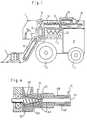
- the harvesting machine carries at its front end a mowing tool (7), for example a rotary mower with pre-shredding devices, which cuts and shreds the crop to be harvested.
- An inclined conveyor (9) transfers the pre-shredded straw to a vertical conveyor (11), which feeds it to a deflection roller (13) of a re-shredding unit arranged in the upper area of the harvesting machine.
- the deflecting roller (13) passes the shredded straw to a trough screw (15), to which a press screw (17) is connected.
- the outlet of the press screw (17) ends in a pelletizing device (19) which will be explained in more detail below and which compresses the straw material pre-compressed by the press screw (17) to form pourable pellets.
- the pelletizing device (19) is arranged above a bunker (21) which is arranged in the rear area of the harvesting machine and receives the pellets.
- the pelletizing device (see FIGS. 2 and 3) comprises two pelletizing bodies, which are mounted parallel to one another and are designed as hollow rollers (33) and have webs and shafts which engage in one another on their circumference, and above a heat cycle from the waste heat of the internal combustion engine (5) to at least 100 ° C, but preferably to more than 150 ° C, are heated.
- the heat circuit comprises a heat exchanger (23) connected to the coolant circuit of the internal combustion engine or as such forms the coolant circuit and is connected via connecting lines (25) to heat medium channels of the pelletizing bodies which will be explained in more detail below.
- the internal combustion engine (5) not only drives the wheels (3) of the harvesting machine, but at least also the pelletizing body of the pelletizing device (19) and possibly also the rotary mower tool (7) including the conveyors (9) to (17).
- a significant increase in the efficiency of the overall system is achieved when the exhaust gases from the internal combustion engine (5) are used to heat the pelletizing device. Then, without further energy supply, the pressing elements can be heated to approximately 165 ° C., which has been found to be optimal for the pressing process.
- FIG. 14 shows an alternative to FIG. 1 harvesting machine (2) which can be controlled from the driver's cab (1) and is driven by an internal combustion engine (5).
- the harvesting machine carries a pick-up pick-up device (4) for straw crops, a side screw conveyor (6), which is offset above and in the direction of travel, consisting of a tube with two screw fronds, which convey the pick-up material to the center.
- a side screw conveyor (6) which is offset above and in the direction of travel, consisting of a tube with two screw fronds, which convey the pick-up material to the center.
- controlled conveyor tines (8) conveyed into the inlet area (10) of a pressing device (12) and crushed on cutting knives (14) projecting into the conveying path.
- pelletizing device consisting of two hollow rollers (33) arranged parallel to one another (see FIG. 5) is shown schematically in the drawing as the pressing device (12).
- a screw compressor can also be used.
- pellets or compacts are conveyed into a bunker (21) with an elevator (16).
- the arrangement of the pressing device immediately behind a recording device or a mowing device for the material to be pressed is also of independent, inventive importance if the pressing device is not designed as an exchangeable structural unit, because it is advantageous for the work process if the material to be pressed compresses immediately after the recording the transport route for the low-density goods is short.
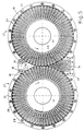
- the pelletizers have the shape of two hollow rollers (33) which are rotatably mounted axially parallel to one another in a housing (27) on bearings (29, 31) are driven by a drive shaft (37) rotating in opposite directions via a gear transmission (35).
- the ring gears (33) have a number of webs (39) which run approximately in the axial longitudinal section and enclose a cavity (41).
- the webs (39) are detachably fastened axially between a plate-shaped flange body (43), which in turn is held on an axle journal (45) connected to the gear (35), and on the other hand on an annular flange body (49 that surrounds an outlet opening (47) ).
- adjacent webs (39) delimit a press channel (shaft) (51) which tapers approximately wedge-shaped towards the cavity (41) and is continuous from the outer circumference to the inner circumference of the circumferential wall.
- the radially outer end regions of the webs (39) of the respective other hollow roller engage as press rams in the axially elongated shafts (51) which are elongated in cross section, while the hollow rollers (33) rotate in opposite directions. Crops that are forcibly conveyed and shredded by the press screw (17) into the rolling gap of the two hollow rollers (33) are pressed into the shafts (51) by the webs (39) and compacted there.
- the dimensions of the webs (39) are selected so that they engage with cut air in the shafts (51), ie do not touch each other, while the ring gears (33) are forcibly driven relative to one another via the gear (35).
- the webs (39) contain heat medium channels (57) which are connected via the flange body (43) and the axle journal (45) to a rotary fluid coupling (59) to which the heat medium lines (25) are connected.
- Liquid heat transfer medium for example in the form of a heat-resistant oil or the like, circulates in the heat medium channels (57) from the heat exchanger (23) of the internal combustion engine (5) to at least 150 ° C.
- the temperature control of the crop to be pelletized in the shafts (51) reduces the drive power required to drive the hollow rollers (33) and reduces the pressure in the shafts (51) required for compacting.
- a heat pump can optionally be connected into the heat medium circuit if the temperature level supplied by the internal combustion engine (5) is too low.
- the heat medium channels (57) are also in the housing (61) of the press screw forming the feed path (17), as well as in the areas (63) of the housing (27) which closely enclose the hollow rollers (33) except for the feed path Heat exchanger (23) (Fig. 1) connected heat medium channels (65) are provided.
- the heat medium channels (65) in the housing walls (63) or the housing tube (61) can optionally be omitted. If the heat output of the heat medium channels (65) is sufficient in itself, the heat medium channels (57) of the hollow rollers (33) may also be omitted instead.
- each of the two hollow rollers (33) can be assigned two repressing rollers (67) or (69) which are rotatably mounted axially parallel to the hollow rollers (33) in the housing (27).
- the repressing rollers (67, 69) have only radially projecting punches (71) which engage in the shafts (51) of the associated hollow roller (33).
- the repressing rollers (67, 69) mesh in succession with the associated hollow roller (33), the depth of penetration of the punches (71) increasing in the direction of rotation (73) of the hollow rollers subsequent repressing rollers.
- the different penetration depth of the punches (71) can be achieved by different punch heights and / or different center distance between the repressing rolls and the hollow rolls.
- the pressure rollers (67, 69) can be loosely driven by the engagement of the punches (71); but they can also be forcibly synchronized with the transmission (35).
- the housing (27) is divided transversely to the connecting plane of the hollow roller axes into two housing halves (75), on each of which one of the hollow rollers (33) including the associated repressing rollers (67.69) is stored.
- the housing halves (75) can be adjusted approximately in relation to one another in the direction of the axis connection plane.
- the adjustment movement expediently takes place about the axis of rotation of one of the gearwheels of the transmission (35) in order to be able to maintain the engagement of the gearwheels independently of the adjustment position.
- gear chains ensuring the forced engagement of the hollow rollers, for example in the form of link chains or toothed belts, can also be used.
- the conveying capacity of the press screw (17) is expediently adjustable, for example by varying the screw speed, in order to ensure a uniform and optimal loading of the hollow rollers (33) with material to be pelletized.
- the screw speed is expediently kept at a constant setpoint by means of a control loop.
- a continuously variable, controllable gear can be provided to adjust the screw speed.
- the delivery rate of the press screw can also be varied in other ways, for example by using an axially adjustable cone screw in a cone housing.
- the housing (27) of the pelletizing device has a housing frame (28) and a housing shell (30).
- the housing shell (30) encompasses both hollow bodies (33) with much less play than shown in FIG. 2.
- the Material to be pelletized is forcibly brought into the gusset area of the hollow rollers (33) in the chopped state via a housing connection (32).
- the housing connection (32) has a wedge-shaped cavity (34) widening in the conveying direction.
- a wedge-shaped component (36) is connected to the housing (28, 30), the outer surface (38) of which is almost in sliding friction with the outer end areas of the webs (39).
- the housing shell (30) is not centered on the axis of rotation of the webs (39). If the play between the inner surface of the housing shell (30) and the outer jacket regions of the webs (39) is made variable, in such a way that in the region of the contact point of the webs (39) with the wedge-shaped component (36) there is minimal play (40) and a maximum play (42) is set at the transition from the housing shell (30) to the housing connection (32), then the risk of blocking the rotation of the hollow bodies (33) in the housing (28, 30) is eliminated.
- the difference in the game is relatively small; with a difference of 1 mm, good experiences have been made.
- the invention is not limited to this measurement.
- FIG. 6 shows that the housing connection (32) is adjacent to a screw housing (44) which has a cavity (46) which tapers in a wedge shape in the conveying direction of the material to be pelletized. Accordingly, the press screw (48) guided therein is also wedge-shaped, as can also be seen from FIG. 4.
- the radial length of the webs (39) and thus also the radial length of the shafts (51) located therebetween is substantially greater than the average thickness of the webs (39) or shafts (51). 8 that the penetration depth (52) of the webs (39) into the shafts (51) is relatively minimal.
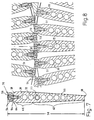
- the geometry of the webs (39), the individual structure of which is shown in a preferred exemplary embodiment in FIG. 7, is such that the web edges (70) should not touch one another when they interlock. Rather, it is intended that a small play remains between the web edges (70).
- the webs (39) therefore do not roll against each other, as is done in the prior art.
- the webs (39) have wear bolts (54) on the outer end face which are fastened to the webs by means of screws (56). These wear bolts (54) are guided with ridges (90) in grooves (84) so that the pressure cannot affect the screws (56).
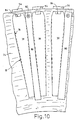
- the wear bar (54) expands in a cuboid shape perpendicular to the plane of the drawing sheet. If, for example, it is assumed that the representation in FIG. 10 corresponds to the natural size of a web (39), the length of the cuboid wear bar (54) is approximately 100 mm.
- the individual web (39) has different thicknesses.
- an undercut (64) opposite a wedge-shaped widening (58) of the web (39).
- an area (60) of constant thickness of the web (39) which can also be designed to widen slightly in a wedge shape, after which the web (39) merges into a wedge-shaped taper (62).
- 6 and 8 clearly show, the outer wall surfaces of the webs (39) determine the shape of the shafts (51) due to their radial arrangement on the hollow body (33).
- the wear bolts (54) initially result in a weak and then by the wedge-shaped extensions (58) a stronger wedge-shaped taper of the shafts (51).
- the regions (60) of constant thickness or slightly wedge-shaped widening of the webs (39) also lead, due to the radial arrangement of the webs (39), to a weakening, wedge-shaped taper of the shafts (51) in the radial direction.
- longitudinal channels (66) have the purpose of letting the gas pressure, which increases sharply when the crop is compacted, escape.
- the longitudinal channels (66) are therefore also open on the inner end face.
- the bores (72) in the webs (39), which extend parallel to the axis of rotation of the hollow bodies (33), are, as already explained in relation to FIGS. 2 and 3, intended to bring a heating medium directly to the pressing members. Efficiency is optimal when the webs are heated to over 150 ° C, especially in the range of 165 ° C.
- the compaction of the stalk material is complete as soon as the material in the shafts (51) has reached the inner end of the region (60) of constant web thickness. Regardless of this, the webs (39) extend much longer in the radial direction, although, due to the wedge-shaped taper (62) of the webs (39), no additional compression is desired.
- the purpose of this measure is to give the pressed stalk material in the shaft (51) a longer dwell time and thus initiate hardening of the material.
- this longer dwell time must not increase the resistance, which is why the wedge-shaped taper (62) and the surface smoothing of the webs (39) are preferred.
- the longitudinal channels (66) also make a significant contribution to degassing and thus to reducing friction.
- the ratio of the penetration depth (52) of the webs (39) or wear bar (54) to the radial length of the webs (39) is extremely different from the prior art.
- the invention proposes to measure this ratio on the order of more than 1: 8, primarily 1:10 to 1:25.
- the invention also shows that the residence time of the molding compound in the shaft can also be optimized by reducing the flow rate of the heating medium in the bores (72) of the webs (39). This can be achieved, for example, by using helices (77) or similar flow obstacles in the bores (72), as is shown in the example of FIGS. 7 and 13.
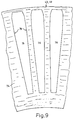
- FIG. 9 shows the partial area of a cheek (74) of the individual flange body (43) in an end view.
- This cheek (74) has regularly distributed recesses or openings (76) which are each intended to receive a web (39), possibly also a pair of adjacent webs (39), as shown in FIG. 10. Accordingly, the edges (78) of the recesses (76) determine the radial position of the individual web (39), which are wedged in this position by a strip (80) against the edges (78).
- This strip (80) needs to be attached to the cheek with only one screw (82), as shown in FIG. 10.
- the webs (39) On their side wall surfaces, the webs (39) have groove-like cutouts (92) which extend in the radial direction and are directly opposite the strips (80) in the assembled state. Because of the profiling of the side wall surfaces of the webs (39), the cutouts (92) are only present in places. The strips (80) engage in the cut-outs (92) and thus form axially parallel stops on both sides of the cheeks (74) and thus prevent axial movement of the webs (39) in the cheeks (74).
- the webs (39) with the projecting areas (86) protrude beyond the outer surfaces of the cheeks (74), which has the meaning that the strips (80) on the outside of the cheeks (74) for wedging the webs (39) arranged and can be brought into effect opposite the projecting areas (86).
- the pelletizing device according to the invention can, as shown in FIG. 12, also be arranged stationary instead of on a harvesting vehicle.
- the structure of the hollow rollers (33) corresponds to the embodiment of FIG. 5.
- the housing (27), not shown, can be arranged in a stationary manner.
- An electric motor (20) is arranged on a mobile frame (18) and drives a conveyor screw in the housing (22) analogously (15) in FIG. 1.
- the stalk material transported and possibly shredded from the field is fed to the conical screw housing (44) (see also FIG. 6), in which a conical screw (48) for forcibly transferring the stalk material to the hollow rollers (33) is located.
- scrapers In the cavities (41) of the hollow rollers (33) there are scrapers (26), which act in the manner of a doctor blade against the inner edges of the webs (39) and break off the compacted strands of the crop material emerging there.
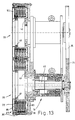
- FIG. 13 shows a floating mounting (79) of the hollow body (33).
- the bearing-side flange body (43) is firmly connected to the drive shaft (45).
- the outlet-side flange body (49) is carried by the flange body (43) over the multiplicity of webs (39).
- the housing (27) consists of the housing frame (28) and the housing shell (30), which are connected to one another via bolts (81) and encompass the webs (39). Chambers (83) and (85) adjoin both ends of the webs (39) and are intended for the supply and removal of heating agents.
- exhaust gases from an internal combustion engine can be guided through the bores (72) of the webs (39).
- helix (77) In order to utilize the heat of the heat medium as fully as possible, it is advisable to arrange elements, for example helix (77), in the bores (72) of the webs (39), which are to reduce the rate of malfunction of the heat medium.
- Such coils (77) are symbolically represented in a bore (72) in FIGS. 7 and 13.
- the aim is to keep the length of the webs (39) and accordingly the press channels (51) as long as possible, as seen in the axial direction of the hollow rollers (33). In this case, relatively wide strands then emerge from the press channels (51), the breaking of which does not automatically ensure that a size which is advantageous for the further processing of the granules is obtained.
- the press channels (51) are divided by partition walls (83) which extend in radial planes with respect to the axis of the hollow rollers (33) and the press channels ( 51) Push through.
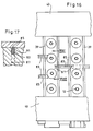
- the individual partition (83) has a wedge shape tapering from the outside inward in the axial view. 16 and 17 that the cross section of the partition (83) is prismatic, in particular rectangular. In this way it is possible to guide the partition wall (83) in grooves (87) of the webs (39), which lie opposite one another.
- the individual press channel (51) can be divided either by a single partition wall (83) or by two or more partition walls (83). 16 further shows symbolically that the webs (39) are guided in flange bodies (43, 49) which, together with the webs (39), the hollow rollers (33) form.
- the individual partition wall (83) has a preferably ridge-like cutting edge (85), which can be formed by chamfering the partition wall (83) in accordance with the exemplary embodiment in FIG. 17.
- This cutting edge (85) has the task of creating the resistance of the partition wall (83) to the pressing pressure that the individual webs (39) produce to the pressing pressure that the individual webs (39) produce when the plant material is stuffed into the pressing channels (51) , to reduce. In this way, a division of the press channels (51) and thus the strands compacted into these press channels (51) is achieved, which leads to a reduction in the width of the granules to be formed.
- the individual partition wall (83) must be secured in its position in order not to become movable under the influence of the pressing pressure.
- the individual partition wall has hammer-head-like projections (89) which engage in grooves (91) in the webs (39) (cf. FIG. 15). These grooves extend in the circumferential direction, based on the movement of the webs (39).
- the individual partition (83) is therefore supported under the influence of the pressing pressure on the bottom of the groove (91).
- the partition (83) or the individual hammer-head-like extension (89) is braked by a stop surface (93) of a wear bar (54) which forms the actual cutting edges of the web (39). 17, these wear bolts (54) are fixed to the end faces of the webs (39) by means of screws (94).
- the cutting edge (85) extends, as shown in FIG. 16, only between the mutually facing side surfaces of the wear bars (54). In this way it is prevented that side channels are formed by the bevel along the stop surface.
- the cutting edge (85) is flush with the laterally adjacent end faces of the partition (83).
- Fig. 18 symbolically represents a grinding device (96) which can be moved back and forth parallel to the axis of the individual hollow roller (33) and accordingly along the cutting edge (70) of the individual web (39) or its wear bar (54).
- a rotatingly driven grinding roller (98) is occasionally moved back and forth along the arrow (99) on an axis (97) parallel to the axis. This grinding roller smoothes the circumferential surface of the wear bar (54) and thus sharpens the cutting or web edge (70).
Landscapes
- Chemical & Material Sciences (AREA)
- Mechanical Engineering (AREA)
- Engineering & Computer Science (AREA)
- Life Sciences & Earth Sciences (AREA)
- Organic Chemistry (AREA)
- Environmental Sciences (AREA)
- Chemical Kinetics & Catalysis (AREA)
- Oil, Petroleum & Natural Gas (AREA)
- Geology (AREA)
- Geochemistry & Mineralogy (AREA)
- General Life Sciences & Earth Sciences (AREA)
- Environmental & Geological Engineering (AREA)
- Apparatuses For Bulk Treatment Of Fruits And Vegetables And Apparatuses For Preparing Feeds (AREA)
- Fodder In General (AREA)
- Formation And Processing Of Food Products (AREA)
- Engine Equipment That Uses Special Cycles (AREA)
- Processing And Handling Of Plastics And Other Materials For Molding In General (AREA)
- Processing Of Solid Wastes (AREA)
Applications Claiming Priority (9)
| Application Number | Priority Date | Filing Date | Title |
|---|---|---|---|
| DE19924214111 DE4214111A1 (de) | 1992-04-29 | 1992-04-29 | Pressvorrichtung |
| DE4214111 | 1992-04-29 | ||
| DE4227928 | 1992-08-22 | ||
| DE19924227928 DE4227928A1 (de) | 1992-04-29 | 1992-08-22 | Anordnung einer Preßvorrichtung |
| DE9301258 | 1993-01-29 | ||
| DE9301258U | 1993-01-29 | ||
| DE9304636U | 1993-03-29 | ||
| DE9304636U DE9304636U1 (de) | 1993-03-29 | 1993-03-29 | Vorrichtung zum Pelletieren von pflanzlichem Gut, insbesondere Halmgut |
| PCT/EP1993/000990 WO1993022132A1 (de) | 1992-04-29 | 1993-04-23 | Vorrichtung zum pelletieren von pflanzlichem gut |
Publications (2)
| Publication Number | Publication Date |
|---|---|
| EP0638018A1 EP0638018A1 (de) | 1995-02-15 |
| EP0638018B1 true EP0638018B1 (de) | 1995-11-15 |
Family
ID=27435451
Family Applications (1)
| Application Number | Title | Priority Date | Filing Date |
|---|---|---|---|
| EP93911500A Expired - Lifetime EP0638018B1 (de) | 1992-04-29 | 1993-04-23 | Vorrichtung zum pelletieren von pflanzlichem gut |
Country Status (8)
| Country | Link |
|---|---|
| US (1) | US5622037A (da) |
| EP (1) | EP0638018B1 (da) |
| AT (1) | ATE130247T1 (da) |
| CA (1) | CA2128523C (da) |
| DE (1) | DE59300968D1 (da) |
| DK (1) | DK0638018T3 (da) |
| ES (1) | ES2079977T3 (da) |
| WO (1) | WO1993022132A1 (da) |
Cited By (1)
| Publication number | Priority date | Publication date | Assignee | Title |
|---|---|---|---|---|
| EP2289682A1 (de) | 2009-08-28 | 2011-03-02 | Reichardt Projectmanagement GmbH & Co. KG | Verfahren und Vorrichtung zur Herstellung von Formlingen aus Biomasse |
Families Citing this family (24)
| Publication number | Priority date | Publication date | Assignee | Title |
|---|---|---|---|---|
| DE29606641U1 (de) * | 1996-04-12 | 1997-08-07 | Haimer, Franz, 86568 Hollenbach | Hohlwalze zum Pelletieren von pflanzlichem Gut |
| IT1286890B1 (it) * | 1996-12-04 | 1998-07-17 | Ecogest Srl | Macchina per la compattazione di materiali solidi |
| US5820893A (en) * | 1997-01-23 | 1998-10-13 | Westvaco Corporation | Breakaway scraper blade assembly for a pelletizer |
| DE29920772U1 (de) * | 1998-11-12 | 2000-03-02 | FLZ Faser Logistik Zentrum Schwarza GmbH, 07407 Rudolstadt | Granulat und Vorrichtung zu seiner Herstellung |
| US7108767B2 (en) * | 2004-08-18 | 2006-09-19 | Noto Vincent H | Pyrolysis machine |
| CN100402137C (zh) * | 2005-10-17 | 2008-07-16 | 缪建通 | 立窑生料造粒机 |
| EP2383032A1 (en) * | 2008-11-25 | 2011-11-02 | Kerry Biomass Technology Limited | A pellet forming system |
| US20130309344A1 (en) * | 2010-06-14 | 2013-11-21 | Klaus Werner Posselt | Double die pellet machine |
| FI127057B (fi) * | 2010-12-17 | 2017-10-31 | Teknologian Tutkimuskeskus Vtt Oy | Laite ja menetelmä massan muokkaamiseksi ja puristamiseksi |
| AT510870B1 (de) * | 2011-01-03 | 2012-09-15 | Josef Schaider Privatstiftung | Vorrichtung zum herstellen von presslingen |
| JP5851781B2 (ja) * | 2011-09-26 | 2016-02-03 | 三井造船株式会社 | ガスハイドレート圧縮成形装置 |
| CN102555265A (zh) * | 2012-02-29 | 2012-07-11 | 李瑞喜 | 双辊模互塞式生物质致密塑型装置 |
| WO2014130003A2 (en) | 2013-02-20 | 2014-08-28 | Tumagyan Ashot | Processing straw into more nutritional products |
| CN103350007A (zh) * | 2013-07-05 | 2013-10-16 | 江苏普阳环保能源科技有限公司 | 一种秸秆破碎压块装置 |
| DE102014002775A1 (de) | 2014-02-24 | 2015-08-27 | Friedrich Simeth | Vorrichtung und Verfahren zur Herstellung von Biomasse-Presslingen |
| AT516796B1 (de) | 2015-02-11 | 2018-02-15 | Josef Schaider Privatstiftung | Pelletiereinrichtung |
| ES2590556B1 (es) * | 2015-05-22 | 2017-09-07 | Ianus Ingenieria, S.L.U. | Maquina móvil de peletizado. |
| DE102015014120A1 (de) * | 2015-11-04 | 2017-05-04 | Maschinenfabrik Bernard Krone Gmbh | Vorrichtung zum Kompaktieren von faserigem Halmgut |
| CN110419319B (zh) * | 2019-09-05 | 2020-12-25 | 中国农业大学 | 一种秸秆多级精细粉碎抛撒还田装置 |
| CN110975757B (zh) * | 2019-12-03 | 2021-10-08 | 江苏三仪动物营养科技有限公司 | 一种浓缩饲料颗粒机 |
| CN112604601A (zh) * | 2020-12-24 | 2021-04-06 | 宁英琪 | 一种用于颗粒饲料生产的挤压造粒装置 |
| CN112473559A (zh) * | 2020-12-31 | 2021-03-12 | 安徽华塑股份有限公司 | 一种电石生产回收用的焦粉成球机 |
| BE1030209B1 (nl) * | 2022-01-24 | 2023-08-21 | Schots Technics Bvba | Werkwijze voor een optimale oogst van bermbegroeiing |
| CN118901413B (zh) * | 2024-09-20 | 2025-09-12 | 吉林大学 | 一种轴流分段式玉米秸秆粉碎装置 |
Family Cites Families (23)
| Publication number | Priority date | Publication date | Assignee | Title |
|---|---|---|---|---|
| DE7244248U (de) * | 1973-03-15 | Hamburger Maschinenbau Jost Hinrich Raydt | Vorrichtung zur Herstellung von pelletiertem Kraftfutter | |
| DE564638C (de) * | 1932-11-21 | Albert William Sizer | Zweiwalzige Formmaschine zum Herstellen von Futterkuegelchen | |
| DE317814C (da) * | ||||
| GB339868A (en) * | 1930-02-06 | 1930-12-18 | William Booth | Improvements in or relating to the manufacture of briquettes |
| GB380987A (en) * | 1930-11-08 | 1932-09-29 | Arno Andreas | Improvements in or relating to the production of lumps of pulverous material |
| DE971550C (de) * | 1952-07-24 | 1959-02-12 | Amandus Kahl Nachf | Verfahren und Vorrichtung zur Herstellung von gepressten Futtermitteln in Granularform |
| DE1208936B (de) * | 1960-01-12 | 1966-01-13 | Harry J Immohr | Pelletisier-Pressform |
| CA737226A (en) * | 1960-06-17 | 1966-06-28 | National Frost Protection Co. | Machine for forming pellets and the like |
| DE1215997B (de) * | 1960-11-02 | 1966-05-05 | John Deere Lanz Ag | Verfahren und Vorrichtung zum Verarbeiten von landwirtschaftlichem Erntegut |
| US3230903A (en) * | 1962-05-14 | 1966-01-25 | Massey Ferguson Inc | Hay wafering method and apparatus |
| US3192881A (en) * | 1963-10-22 | 1965-07-06 | Massey Ferguson Services Nv | Machine for wafering forage crop material |
| US3517488A (en) * | 1967-07-03 | 1970-06-30 | Massey Ferguson Services Nv | Machine for compacting forage crops |
| DE2151865A1 (de) * | 1970-11-11 | 1972-05-18 | Leuna Werke Veb | Vorrichtung zum Granulieren von thermoplastischen Kunststoffen und Polyolefinwachsen |
| US3859026A (en) * | 1972-02-29 | 1975-01-07 | Glen E Osborn | Haycuber |
| DD144230B1 (de) * | 1979-06-08 | 1987-01-14 | Inst F D Gaerungs U Getraenkei | Verfahren und vorrichtung zur herstellung von pellets aus pflanzlichen und tierischen materialien, insbesondere aus hopfen |
| SU846303A1 (ru) * | 1979-12-25 | 1981-07-15 | Институт черной металлургии | Валковый пресс дл брикетировани |
| DE3233121A1 (de) * | 1982-09-07 | 1984-03-08 | Franz Prof.Dr.-Ing. 3406 Bovenden Wieneke | Verfahren zur herstellung haltbar verdichteter pflanzen- und faserstoffe |
| SU1159639A1 (ru) * | 1983-02-15 | 1985-06-07 | Головной Экспериментально-Конструкторский Институт По Машинам Для Переработки Травы И Соломы | Валково-ленточный брикетный пресс |
| JPS6051788A (ja) * | 1983-08-31 | 1985-03-23 | Yasuo Kakiuchi | 燃料用ペレット及びその製造方法並びに製造装置 |
| SU1440739A1 (ru) * | 1987-02-24 | 1988-11-30 | Б.В.Боклан, В.П.Л люк, А.Д.Учитель, Ю.И.Бургутин, В.Т.Садовник, Б.Г.Федоров, Е.З.Пономарев, Ю.С.Дь ченко и Т.Г.Чайкина | Валково-ленточный брикетный пресс |
| US4824352A (en) * | 1987-10-16 | 1989-04-25 | Hadley Richard S | Apparatus for pelletizing materials |
| DE3831528A1 (de) * | 1988-09-16 | 1990-03-29 | Franz Haimer | Vorrichtung zum brikettieren von pflanzlichem gut, insbesondere halmgut |
| US5156570A (en) * | 1991-09-23 | 1992-10-20 | Justice Iii James C | Combine-grain dryer |
-
1993
- 1993-04-23 AT AT93911500T patent/ATE130247T1/de not_active IP Right Cessation
- 1993-04-23 EP EP93911500A patent/EP0638018B1/de not_active Expired - Lifetime
- 1993-04-23 ES ES93911500T patent/ES2079977T3/es not_active Expired - Fee Related
- 1993-04-23 DE DE59300968T patent/DE59300968D1/de not_active Expired - Fee Related
- 1993-04-23 WO PCT/EP1993/000990 patent/WO1993022132A1/de not_active Ceased
- 1993-04-23 DK DK93911500.2T patent/DK0638018T3/da active
- 1993-04-23 CA CA002128523A patent/CA2128523C/en not_active Expired - Fee Related
-
1994
- 1994-08-03 US US08/285,225 patent/US5622037A/en not_active Expired - Lifetime
Cited By (1)
| Publication number | Priority date | Publication date | Assignee | Title |
|---|---|---|---|---|
| EP2289682A1 (de) | 2009-08-28 | 2011-03-02 | Reichardt Projectmanagement GmbH & Co. KG | Verfahren und Vorrichtung zur Herstellung von Formlingen aus Biomasse |
Also Published As
| Publication number | Publication date |
|---|---|
| DE59300968D1 (de) | 1995-12-21 |
| ATE130247T1 (de) | 1995-12-15 |
| DK0638018T3 (da) | 1995-12-18 |
| US5622037A (en) | 1997-04-22 |
| CA2128523A1 (en) | 1993-11-11 |
| WO1993022132A1 (de) | 1993-11-11 |
| CA2128523C (en) | 2005-12-20 |
| ES2079977T3 (es) | 1996-01-16 |
| EP0638018A1 (de) | 1995-02-15 |
Similar Documents
| Publication | Publication Date | Title |
|---|---|---|
| EP0638018B1 (de) | Vorrichtung zum pelletieren von pflanzlichem gut | |
| DE69608918T3 (de) | Zerkleinerungsvorrichtung | |
| EP2892715B1 (de) | Vorrichtung zum kompaktieren von faserigem pflanzengut, insbesondere zum kompaktieren von halmgut | |
| EP1945017B1 (de) | Zerkleinerungseinrichtung für erntegut | |
| EP0856246B1 (de) | Nachzerkleinerungsvorrichtung | |
| EP0748583A1 (de) | Mähdrescher | |
| WO2017162230A1 (de) | Zweiwalzenbrecher | |
| DE3234657C2 (da) | ||
| DE4214111A1 (de) | Pressvorrichtung | |
| DE4115069C2 (de) | Vorrichtung zum Zerkleinern von fasrigen Komponenten in einer biologischen Grundmasse | |
| EP0710175A1 (de) | Aus pflanzlichem material durch pelletieren hergestellter presskörper und vorrichtung zu seiner herstellung | |
| DE1577229A1 (de) | Verfahren und Einrichtung zum Herstellen von Pressballen | |
| DE29616319U1 (de) | Walzenbrecher | |
| DE3406285C2 (da) | ||
| DE3228517A1 (de) | Verdichtungssystem zum zusammenpressen und verdichten von pulverisierten abfallstoffen in brennstoffwuerfel | |
| EP2823702B1 (de) | Nachzerkleinerungsvorrichtung | |
| EP0119208A1 (de) | Schneckenpresse. | |
| DE9309739U1 (de) | Vorrichtung zum Pelletieren von pflanzlichem Gut | |
| WO2004082909A1 (de) | Zerkleinerungseinrichtung für stückholz | |
| DE7818838U1 (de) | Maschine zum zerkleinern von abfallstoffen | |
| DE9408205U1 (de) | Anhänger zum Mischen, Zerkleinern und Verteilen von Tierfutter | |
| DE102013104587B4 (de) | Profilierte Zerkleinerungsscheibe, Zerkleinerungswalze und Zerkleinerungseinrichtung für Erntemaschinen | |
| DE19700653C1 (de) | Einfüllvorrichtung für Abfall und Verfahren zur Beschickung einer Kammer oder einer Fördereinrichtung mit Abfall | |
| AT406354B (de) | Zerkleinerungsvorrichtung | |
| EP0956901A1 (de) | Schneidwelle mit Schneidwerkzeugen für eine Zerkleinerungsmaschine |
Legal Events
| Date | Code | Title | Description |
|---|---|---|---|
| PUAI | Public reference made under article 153(3) epc to a published international application that has entered the european phase |
Free format text: ORIGINAL CODE: 0009012 |
|
| 17P | Request for examination filed |
Effective date: 19940621 |
|
| AK | Designated contracting states |
Kind code of ref document: A1 Designated state(s): AT CH DE DK ES FR GB IT LI NL SE |
|
| 17Q | First examination report despatched |
Effective date: 19950328 |
|
| GRAA | (expected) grant |
Free format text: ORIGINAL CODE: 0009210 |
|
| AK | Designated contracting states |
Kind code of ref document: B1 Designated state(s): AT CH DE DK ES FR GB IT LI NL SE |
|
| REF | Corresponds to: |
Ref document number: 130247 Country of ref document: AT Date of ref document: 19951215 Kind code of ref document: T |
|
| GBT | Gb: translation of ep patent filed (gb section 77(6)(a)/1977) |
Effective date: 19951114 |
|
| REG | Reference to a national code |
Ref country code: DK Ref legal event code: T3 |
|
| REF | Corresponds to: |
Ref document number: 59300968 Country of ref document: DE Date of ref document: 19951221 |
|
| ET | Fr: translation filed | ||
| REG | Reference to a national code |
Ref country code: ES Ref legal event code: FG2A Ref document number: 2079977 Country of ref document: ES Kind code of ref document: T3 |
|
| ITF | It: translation for a ep patent filed | ||
| REG | Reference to a national code |
Ref country code: CH Ref legal event code: NV Representative=s name: E. BLUM & CO. PATENTANWAELTE |
|
| PG25 | Lapsed in a contracting state [announced via postgrant information from national office to epo] |
Ref country code: LI Effective date: 19960430 Ref country code: CH Effective date: 19960430 |
|
| PLBE | No opposition filed within time limit |
Free format text: ORIGINAL CODE: 0009261 |
|
| STAA | Information on the status of an ep patent application or granted ep patent |
Free format text: STATUS: NO OPPOSITION FILED WITHIN TIME LIMIT |
|
| 26N | No opposition filed | ||
| REG | Reference to a national code |
Ref country code: CH Ref legal event code: PL |
|
| PGFP | Annual fee paid to national office [announced via postgrant information from national office to epo] |
Ref country code: NL Payment date: 20010329 Year of fee payment: 9 |
|
| REG | Reference to a national code |
Ref country code: GB Ref legal event code: IF02 |
|
| PGFP | Annual fee paid to national office [announced via postgrant information from national office to epo] |
Ref country code: DK Payment date: 20020327 Year of fee payment: 10 Ref country code: SE Payment date: 20020327 Year of fee payment: 10 |
|
| PGFP | Annual fee paid to national office [announced via postgrant information from national office to epo] |
Ref country code: AT Payment date: 20020328 Year of fee payment: 10 |
|
| PG25 | Lapsed in a contracting state [announced via postgrant information from national office to epo] |
Ref country code: NL Free format text: LAPSE BECAUSE OF NON-PAYMENT OF DUE FEES Effective date: 20021101 |
|
| NLV4 | Nl: lapsed or anulled due to non-payment of the annual fee |
Effective date: 20021101 |
|
| PG25 | Lapsed in a contracting state [announced via postgrant information from national office to epo] |
Ref country code: AT Free format text: LAPSE BECAUSE OF NON-PAYMENT OF DUE FEES Effective date: 20030423 |
|
| PG25 | Lapsed in a contracting state [announced via postgrant information from national office to epo] |
Ref country code: SE Free format text: LAPSE BECAUSE OF NON-PAYMENT OF DUE FEES Effective date: 20030424 |
|
| PG25 | Lapsed in a contracting state [announced via postgrant information from national office to epo] |
Ref country code: DK Free format text: LAPSE BECAUSE OF NON-PAYMENT OF DUE FEES Effective date: 20030430 |
|
| PGFP | Annual fee paid to national office [announced via postgrant information from national office to epo] |
Ref country code: ES Payment date: 20030523 Year of fee payment: 11 |
|
| EUG | Se: european patent has lapsed | ||
| REG | Reference to a national code |
Ref country code: DK Ref legal event code: EBP |
|
| PG25 | Lapsed in a contracting state [announced via postgrant information from national office to epo] |
Ref country code: ES Free format text: LAPSE BECAUSE OF NON-PAYMENT OF DUE FEES Effective date: 20040424 |
|
| PG25 | Lapsed in a contracting state [announced via postgrant information from national office to epo] |
Ref country code: IT Free format text: LAPSE BECAUSE OF NON-PAYMENT OF DUE FEES;WARNING: LAPSES OF ITALIAN PATENTS WITH EFFECTIVE DATE BEFORE 2007 MAY HAVE OCCURRED AT ANY TIME BEFORE 2007. THE CORRECT EFFECTIVE DATE MAY BE DIFFERENT FROM THE ONE RECORDED. Effective date: 20050423 |
|
| REG | Reference to a national code |
Ref country code: ES Ref legal event code: FD2A Effective date: 20040424 |
|
| PGFP | Annual fee paid to national office [announced via postgrant information from national office to epo] |
Ref country code: FR Payment date: 20090414 Year of fee payment: 17 Ref country code: DE Payment date: 20090422 Year of fee payment: 17 |
|
| PGFP | Annual fee paid to national office [announced via postgrant information from national office to epo] |
Ref country code: GB Payment date: 20090421 Year of fee payment: 17 |
|
| GBPC | Gb: european patent ceased through non-payment of renewal fee |
Effective date: 20100423 |
|
| REG | Reference to a national code |
Ref country code: FR Ref legal event code: ST Effective date: 20101230 |
|
| PG25 | Lapsed in a contracting state [announced via postgrant information from national office to epo] |
Ref country code: DE Free format text: LAPSE BECAUSE OF NON-PAYMENT OF DUE FEES Effective date: 20101103 |
|
| PG25 | Lapsed in a contracting state [announced via postgrant information from national office to epo] |
Ref country code: GB Free format text: LAPSE BECAUSE OF NON-PAYMENT OF DUE FEES Effective date: 20100423 |
|
| PG25 | Lapsed in a contracting state [announced via postgrant information from national office to epo] |
Ref country code: FR Free format text: LAPSE BECAUSE OF NON-PAYMENT OF DUE FEES Effective date: 20100430 |