EP0638169B1 - Procede et dispositif de detection de decharge d'hydrocarbures a l'etat liquide dans l'eau, sur le sol ou dans le sous-sol - Google Patents
Procede et dispositif de detection de decharge d'hydrocarbures a l'etat liquide dans l'eau, sur le sol ou dans le sous-sol Download PDFInfo
- Publication number
- EP0638169B1 EP0638169B1 EP93912008A EP93912008A EP0638169B1 EP 0638169 B1 EP0638169 B1 EP 0638169B1 EP 93912008 A EP93912008 A EP 93912008A EP 93912008 A EP93912008 A EP 93912008A EP 0638169 B1 EP0638169 B1 EP 0638169B1
- Authority
- EP
- European Patent Office
- Prior art keywords
- absorbent body
- sensor
- detector device
- detection
- alteration
- Prior art date
- Legal status (The legal status is an assumption and is not a legal conclusion. Google has not performed a legal analysis and makes no representation as to the accuracy of the status listed.)
- Expired - Lifetime
Links
- XLYOFNOQVPJJNP-UHFFFAOYSA-N water Substances O XLYOFNOQVPJJNP-UHFFFAOYSA-N 0.000 title claims abstract description 42
- 238000001514 detection method Methods 0.000 title claims abstract description 41
- 229930195733 hydrocarbon Natural products 0.000 title claims abstract description 36
- 150000002430 hydrocarbons Chemical class 0.000 title claims abstract description 36
- 238000000034 method Methods 0.000 title claims abstract description 32
- 239000007788 liquid Substances 0.000 title claims abstract description 20
- 230000002745 absorbent Effects 0.000 claims abstract description 68
- 239000002250 absorbent Substances 0.000 claims abstract description 68
- 238000002604 ultrasonography Methods 0.000 claims abstract description 28
- 230000003287 optical effect Effects 0.000 claims abstract description 27
- 230000004075 alteration Effects 0.000 claims abstract description 25
- 239000000463 material Substances 0.000 claims abstract description 15
- 238000010521 absorption reaction Methods 0.000 claims abstract description 11
- 239000003673 groundwater Substances 0.000 claims abstract description 7
- 239000004744 fabric Substances 0.000 claims description 28
- 239000004215 Carbon black (E152) Substances 0.000 claims description 12
- 238000012544 monitoring process Methods 0.000 claims description 9
- -1 polypropylene Polymers 0.000 claims description 8
- 239000004743 Polypropylene Substances 0.000 claims description 6
- 229920001155 polypropylene Polymers 0.000 claims description 6
- 230000008859 change Effects 0.000 claims description 5
- 230000000007 visual effect Effects 0.000 claims description 2
- 238000006243 chemical reaction Methods 0.000 claims 2
- 239000002480 mineral oil Substances 0.000 claims 2
- 235000010446 mineral oil Nutrition 0.000 claims 2
- 239000003921 oil Substances 0.000 claims 1
- 208000028659 discharge Diseases 0.000 description 20
- 238000005259 measurement Methods 0.000 description 16
- UEUXEKPTXMALOB-UHFFFAOYSA-J tetrasodium;2-[2-[bis(carboxylatomethyl)amino]ethyl-(carboxylatomethyl)amino]acetate Chemical compound [Na+].[Na+].[Na+].[Na+].[O-]C(=O)CN(CC([O-])=O)CCN(CC([O-])=O)CC([O-])=O UEUXEKPTXMALOB-UHFFFAOYSA-J 0.000 description 13
- 230000002596 correlated effect Effects 0.000 description 2
- 230000002209 hydrophobic effect Effects 0.000 description 2
- 239000004745 nonwoven fabric Substances 0.000 description 2
- 239000011358 absorbing material Substances 0.000 description 1
- 230000008901 benefit Effects 0.000 description 1
- 230000005540 biological transmission Effects 0.000 description 1
- 230000008878 coupling Effects 0.000 description 1
- 238000010168 coupling process Methods 0.000 description 1
- 238000005859 coupling reaction Methods 0.000 description 1
- 230000001419 dependent effect Effects 0.000 description 1
- 230000000694 effects Effects 0.000 description 1
- 230000007613 environmental effect Effects 0.000 description 1
- 238000002474 experimental method Methods 0.000 description 1
- 238000011065 in-situ storage Methods 0.000 description 1
- 235000015110 jellies Nutrition 0.000 description 1
- 239000008274 jelly Substances 0.000 description 1
- 238000004519 manufacturing process Methods 0.000 description 1
- 230000007246 mechanism Effects 0.000 description 1
- 239000003305 oil spill Substances 0.000 description 1
- 230000000737 periodic effect Effects 0.000 description 1
- 230000001681 protective effect Effects 0.000 description 1
- 229920006395 saturated elastomer Polymers 0.000 description 1
- 230000035945 sensitivity Effects 0.000 description 1
- 230000011664 signaling Effects 0.000 description 1
- 238000003860 storage Methods 0.000 description 1
- 239000000126 substance Substances 0.000 description 1
- 239000002352 surface water Substances 0.000 description 1
- 239000004753 textile Substances 0.000 description 1
- 239000002699 waste material Substances 0.000 description 1
- 239000002759 woven fabric Substances 0.000 description 1
Images


Classifications
-
- G—PHYSICS
- G01—MEASURING; TESTING
- G01N—INVESTIGATING OR ANALYSING MATERIALS BY DETERMINING THEIR CHEMICAL OR PHYSICAL PROPERTIES
- G01N33/00—Investigating or analysing materials by specific methods not covered by groups G01N1/00 - G01N31/00
- G01N33/18—Water
- G01N33/1886—Water using probes, e.g. submersible probes, buoys
-
- G—PHYSICS
- G01—MEASURING; TESTING
- G01N—INVESTIGATING OR ANALYSING MATERIALS BY DETERMINING THEIR CHEMICAL OR PHYSICAL PROPERTIES
- G01N33/00—Investigating or analysing materials by specific methods not covered by groups G01N1/00 - G01N31/00
- G01N33/18—Water
- G01N33/1826—Organic contamination in water
- G01N33/1833—Oil in water
-
- G—PHYSICS
- G01—MEASURING; TESTING
- G01N—INVESTIGATING OR ANALYSING MATERIALS BY DETERMINING THEIR CHEMICAL OR PHYSICAL PROPERTIES
- G01N33/00—Investigating or analysing materials by specific methods not covered by groups G01N1/00 - G01N31/00
- G01N33/24—Earth materials
- G01N33/241—Earth materials for hydrocarbon content
Definitions
- the invention concerns a method for the detection of hydrocarbons in liquid form at normal ambient temperature, in water, on the ground or in the subsurface, especially for the detection of oil spillage on water or in ground water.
- the invention also concerns a detector device for the execution of the method according to the invention.
- the United States Patent US-A-3,733,594 discloses an alarm apparatus for detecting and indicating oil slicks.
- the apparatus incorporates a hydrophobic oil absorbent material which floats on the surface of the water. On contact with oil of an oil slick, the hydrophobic material absorbs oil and sinks into the water. Upon sinking to a predetermined depth, an alarm signalling device is actuated thereby indicating the presence of an oil slick.
- the European Patent Application EP-A-0,337,630 discloses an oil leak detecting apparatus comprising an elongated oil sensor supported in a protective tube, which is open at its bottom end for the ingress of leaking oil.
- the sensor is encased in a sheath of non-woven fabric made of an absorbing material such as isotactic polypropylene. When oil penetrates the sensor, an increase in the electrical resistance thereof is detected.
- the United States Patent US-A-4,563,674 discloses a floating sensor for detection of oil leaks at a water surface.
- a cloth layer is affixed to the outside of the detecting device so as to form a boundary of water at a height above the general surface level adjacent to the apparatus.
- the cloth layer is made of a sheet of woven or non-woven fabric made of threads having a large or small water absorption, as desired.
- the detecting device itself absorbs the leakage oil and comprises warning means which operate according to a change in electrical conductivity caused by the absorption of oil.
- the United States Patent US-A-4,223,552 discloses an apparatus for detecting hydrocarbon spills on a water surface.
- a sensing element is embedded in an absorbent material having an affinity for the liquid hydrocarbon.
- a detection circuit measures an electrical property of the sensing element.
- the sensing element is embedded in the absorbent material at a predetermined distance from the surface of the water level being monitored.
- GB-A-1 402 825 discloses a method and device for the determination of the concentration of small amounts of oil in water, wherein the oil is concentrated from oily water into a filter material which absorbs oil and the amount of oil absorbed is measured either by a photoelectric method or a dielectric method.
- the disclosure relies on an active absorption method and presupposes an already detected oil spill, before proceeding to the concentration measurement of a locally acquired sample. It is not suitable for instant and automatic detection of possible oil spills over a wide area, e.g. by means of distributed, passive, simple and inexpensive detectors.
- the object of the present invention is to develop a simple and inexpensive detection principle and thereafter to use this detection principle in a simple detector device which permits the detection of the discharge of hydrocarbons in liquid form both at sea, on the ground and in the subsurface.
- Fig. 1 is a detector device according to an embodiment of the invention, based on the use of ultrasound.
- Fig. 2 is a detector device according to an embodiment of the invention, based on/the use of light reflection.
- Fig. 3 is another embodiment of a detector device based on the use of light reflection.
- Fig. 4 is a detector device according to an embodiment based on the measurement of the dielectric constant.
- Fig. 5 is a detector device according to an embodiment based on the measurement of buoyancy.
- Fig. 6 is a detector device according to an embodiment based on a combination of two different detection principles.
- Fig. 7 is a detector device used for the detection of leakage from a buried oil tank.
- the method and the detector device according to the present invention are based on the use of a material which has the ability to attract hydrocarbons in liquid form, e.g. oil or other chemicals with a hydrocarbon basis and which exist in liquid form, while at the same time the material does not absorb or become moistened by water.
- a material of this kind is used in an absorbent body, and by absorbing hydrocarbons such as oil, certain of its physical parameters will change.
- "ERGON Sorb” is a so-called “melt-blown” polypropylene cloth which is supplied in whit in different thicknesses. The cloth can absorb 11.2 times its own weight in oil, but only attracts 0.023 times its own weight in water in the course of 15 minutes. Consequently "ERGON Sorb” has a relative affinity oil/water of 11.2/0.023 or a selective absorption capacity for oil which is 487 times greater than that for water. If the "ERGON sorb” cloth is placed under water pressure or compressed under water, it will absorb some water, but the cloth will not become saturated, nor will the cloth's ability to attract hydrocarbons such as oil be destroyed.
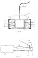
- Fig. 1 shows a detector device based on the use of ultrasound.
- the detector device is equipped with an ultrasound sensor consisting of an ultrasound transducer 1 and an ultrasound reflector 2.
- the ultrasound transducer and the ultrasound reflector can be a combined device with a piezoelectric element cast in a housing as illustrated in fig. 1.
- the absorbent body 3, e.g. in the form of an "ERGON Sorb" cloth, is placed either around the transducer 1 or as shown here, between the transducer 1 and the reflector 2.
- An acoustic jelly 4 is provided between the transducer 1 and the absorbent body 3 in order to improve the acoustic coupling between the transducer 1 and the absorbent body or cloth 3.
- the detector device also may be designed with a transmitter in the form of an ultrasound transducer together with a receiver in the form of a second ultrasound transducer, the transmitter and the receiver respectively being provided on opposite sides of the absorbent body 3, i.e. the "ERGON Sorb" cloth.
- the detector device based on an ultrasound sensor is robust and provides a good signal-noise ratio by using the pulse echo technique.
- a disadvantage of using an ultrasound sensor in a detector device is that it can only be used in water, while at the same time a certain amount of electronics are required for pulse generation and detection.
- the arrangement of the transducer and the reflector is critical with a view to obtaining a good echo, nor should there be any bubbles in the water.
- an increase in pulse level not only provides a stronger echo, but also makes the transducer's position in relation to the reflector less critical.
- a second sensor for use in the detector device is shown in fig. 2.
- This sensor is based on an alteration in the optical reflectance of the absorbent body 3 when the body is moistened with, e.g., oil.
- an absorbent body 3 in the form of an "ERGON Sorb" cloth is used, this cloth is basically white and is a very good reflector of light.
- the difference in reflectance with a moistened and an unmoistened cloth will be dependent on the colour of the oil. It is obvious that a black oil like unrefined oil, waste oil or the like will cause a greater alteration in the reflectance than a clear oil.
- a sensor is used based on an optical transmitter 6, e.g.
- a photo-diode and an optical receiver 7, e.g. a phototransistor.
- the transmitter and the receiver 7 can be installed in the same plane in a sensor housing 5 and shielded from direct light between transmitter and receiver.
- the optical transmitter 6 electronics will be provided which may cause a modulation of the light, a feature which is well known in the art.
- the measurement of reflected light is performed via the phototransistor and the results of the measurement are referred to the measurement conducted with a dry absorbent body, i.e. an unmoistened sheet.
- the detector device in this case can be designed in such a way that the optical transmitter 6 and receiver 7 are provided in the same plane in the sensor housing 5 which is open at one end, but with the opening covered by the absorbent body 3, e.g. in the form of a piece of white "ERGON Sorb" cloth.
- the detector device can also be equipped with an optical sensor with two transmitters 6 and receivers 7 respectively, provided in a respective chamber 12a,b in the detector housing 5, and connected to a supply cable 10, an opening of the chamber being covered in turn by the absorbent body 3 and the detector designed in such a way that the absorbent body will be in contact with the surface of the liquid, for instance by providing a buoyance block 11, if the detector is intended for use in water.
- the respective transceiver pair 6, 7 can be arranged to perform the measurement in different wavelength frequencies.
- One transceiver 6, 7, for example, can perform a measurement in the UV range, while the other can perform a measurement in the IR range.
- the measurements from each of the transceiver pairs can be appropriately correlated in order to provide a more reliable detection.
- the measurements can naturally also be conducted in the wavelength frequency for visible light and there is nothing to prevent an additional pair of transceivers from being used.
- the absorbent body 3 i.e. the "ERGON Sorb" cloth can therefore be impregnated with a hydrocarbon-soluble dye 13. In practical terms this can be done be providing the absorbent body 3 with a dye-impregnated intermediate layer 9. If it becomes moistened with a liquid hydrocarbon such as oil, the hydrocarbon penetrates into the intermediate layer 9 and dissolves the dye, thus adding colour to the absorbent body 3 and providing a greater alteration in the reflectance signal.
- a third embodiment of the detector device according to the invention can be based on the measurement of the dielectric constant for the absorbent body 3. There will be a difference in the dielectric constant for a dry and a moistened absorbent body 3. Oil, e.g., has a relative dielectric constant of 2-3. If the "ERGON Sorb" cloth is used as the absorbent body, it can be assumed that it has the same dielectric constant as air, i.e. a relative dielectric constant of 1. This means that the absorbent body's dielectric constant will alter when it is moistened with oil.
- the detector device in this case can be equipped with a sensor as illustrated in fig. 4. The actual sensor consists of a plate condenser 4 with the absorbent body 3 as dielectric medium.
- the plate condenser 15 is provided in series with an ohmic resistance 13 across the input and output of an oscillator and similarly in series between the input and output of a not shown voltmeter device, the condenser 15 thus being located in a parallel branch 16 between the oscillator 14 and the voltmeter device.
- the alteration in condenser voltage i.e. in the condenser's capacitance, will be a measure of the alteration which is obtained in the dielectric constant when the absorbent body 3 is moistened or dry.
- the problem with a detector device based on the measurement of the dielectric constant is that first of all the detection sensitivity is slight and even only a low absorption of water in the absorbent body 3 will probably lead to a relatively substantial alteration in the measurement values, since the dielectric constant for water is approximately 80 times that for air.
- the advantage of a detector device according to the invention, based on the measurement of the dielectric constant, is that it only requires very simple electronics.
- the detector device according to the invention has to be used on water, the detection of discharge of hydrocarbons can employ an alteration in the absorbent body's buoyancy.
- an "ERGON Sorb" cloth is used as the absorbent body, it will basically have a low specific weight and float easily on the water. At the same time the cloth naturally attracts very little water, but can absorb a large amount of oil, thus causing the buoyancy to alter radically after the absorption of oil.
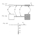
- This can be used in a detector device where the sensor is designed as a buoyancy sensor, as illustrated in fig. 5 which shows the sensor in elevation in (A) and (C) and from above in (B).
- the detector as shown in the figure is designed as a floating body 18 which is connected via a pipe 20 to the absorbent body 3 in the form of a piece of "ERGON Sorb" cloth. Inside the pipe 20 there is provided a ball 19 which can move freely.
- the detector device is arranged in such a way that it will float on the surface 17 of the water (Fig. 5(A)). After the cloth 3 has absorbed the floating hydrocarbon or oil, it will sink.
- the ball 19 in the pipe 20 is intended to provide a hysteresis effect, but, after a certain amount of oil has been absorbed in the absorbent body 3, it will roll through the pipe 20 towards this and cause the detector to change position, e.g. so that the floating body 18 is tipped up (Fig.
- the alteration in the position of the detector by means of a change in the buoyancy of the absorbent body 3 can also be indicated by its being detected by a switch mechanism which triggers an electrical signal which is transferred to a receiver station.
- the electrical signal may also trigger a flashing light mounted on the detector device, or trigger an acoustic signal or activate a radio direction finder.
- the detector device can, e.g., be based both on an ultrasound sensor 21 and an optical sensor 22, as illustrated in fig. 6, wherein the reference numbers denote parts similar to those in Figs. 2 and 3, and the signals from the two sensors can be correlated in order to provide a more reliable indication of the detection of discharge of hydrocarbons such as oil.
- the detector device can be designed as a small buoy and possibly be anchored at a suitable spot.
- the detection signals can then be transferred from each individual detector via a cable system to a central monitoring unit or they may also be transferred by means of a miniaturized radio transmitter provided in the detector.
- Free-floating detectors can be designed as floating buoys and equipped with a radio direction finder. In this case the direction finder will be capable of transmitting a signal automatically when a discharge is detected, thus enabling the position of the discharge to be determined.
- the,detector device When the,detector device is used in the water, it is of course based on the assumption that it must be designed in such a manner that the absorbent body, which itself is basically buoyant, is situated on or near the surface of the water where the discharge of the liquid hydrocarbon will be located. There are a number of ways in which the detector device can be designed in practice, in order to ensure that the absorbent body absorbs discharge on the surface of the water.
- the method and the detector device according to the present invention can naturally also be used for the detection of the discharge of hydrocarbons on the ground, e.g. in the form of leakage from tanks, pipelines or transport vehicles. This is again based on the assumption that the detector device is so positioned and with the absorbent body arranged so as to enable absorption of the discharge to take place and reliable detection to be achieved.
- the detector device can be located in connection with buried oil tanks or the like and detect a leakage from the oil tank as illustrated schematically in fig. 7, showing the oil tank 23 burried beneath the surface level 24 and below the ground water level 25.
- the detector 26 is provided in a detector tube 27 at the ground water level 25 and connected to signal cable 28, the detector tube 27 providing a passage between the detector 26 and an oil trap 29. The whole arrangement with the tank is enclosed in tarpaulin 30.
- the detector can also be used for the detection of oil pollution in the ground water in which case it naturally does not need to be located in the vicinity of the pollution source.
- buried detectors connected with a monitoring system can be used for rubbish dumps, industrial sites and the like where the possibility exists of a leakage of liquid hydrocarbons into the subsurface.
Landscapes
- Life Sciences & Earth Sciences (AREA)
- Health & Medical Sciences (AREA)
- Chemical & Material Sciences (AREA)
- Engineering & Computer Science (AREA)
- General Physics & Mathematics (AREA)
- Immunology (AREA)
- Physics & Mathematics (AREA)
- Analytical Chemistry (AREA)
- Biochemistry (AREA)
- General Health & Medical Sciences (AREA)
- Food Science & Technology (AREA)
- Medicinal Chemistry (AREA)
- Pathology (AREA)
- Environmental & Geological Engineering (AREA)
- General Life Sciences & Earth Sciences (AREA)
- Geology (AREA)
- Remote Sensing (AREA)
- Investigating Or Analysing Materials By Optical Means (AREA)
- Examining Or Testing Airtightness (AREA)
- Investigating Or Analyzing Non-Biological Materials By The Use Of Chemical Means (AREA)
Abstract
Claims (21)
- Méthode pour la détection d'hydrocarbures présents sous forme liquide à température ambiante normale, utilisable pour la détection dans l'eau, sur le sol ou dans le sol, en particulier pour la détection de la pollution par le pétrole de l'eau ou de l'eau dans le sol, la méthode comprenant les étapes consistant à :utiliser un détecteur ayant un corps absorbant (3) comprenant un matériau en polypropylène qui possède une absorption sélective et passive pour les hydrocarbures liquides, en particulier le pétrole, qui est environ 487 fois plus grande que celle pour l'eau,mettre le détecteur en place quand une fuite d'hydrocarbure se produit, etdétecter un changement dans un ou plusieurs paramètres physiques en relation avec le corps absorbant (3),dans laquelle la détection comprend, soit séparément, soit en combinaison, la détection d'une modification dans le corps absorbant de la transmissivité ultrasonique, une modification dans le corps absorbant de la réflectance optique, une modification dans le corps absorbant de la constante diélectrique, et une modification dans le corps absorbant de la flottabilité dans l'eau.
- Méthode selon la revendication 1, caractérisée en ce que le matériau en polypropylène est sous forme d'un tissu non-tissé.
- Méthode selon la revendication 2, caractérisée en ce que, pour détecter la modification d'un paramètre physique individuel, on utilise un capteur (1,2;6,7;16;18) qui est mis en place pour détecter le paramètre physique respectif.
- Méthode selon la revendication 3, caractérisée en ce que deux ou plus de deux capteurs individuels (1,2;6,7;16;18), mis en place pour détecter les paramètres physiques respectifs, sont combinés dans un dispositif détecteur intégré (21,22).
- Méthode selon l'une des revendications précédentes, caractérisée en ce que, pour détecter la modification dans le corps absorbant de la transmissivité ultrasonique, on utilise un capteur comprenant un émetteur ultrasonique (1) et un récepteur ultrasonique (2) placés respectivement de chaque côté du corps absorbant (3) ou un capteur où le corps absorbant est placé entre un émetteur ultrasonique et un récepteur ultrasonique combinés.
- Méthode selon l'une des revendications 1 à 4, caractérisée en ce que, pour détecter la réflectance optique du corps absorbant, on utilise un capteur comprenant un émetteur optique (6) et un récepteur optique (7) placés respectivement à côté du corps absorbant (3), en sorte que le signal optique transmis par l'émetteur (6) est réfléchi par le corps absorbant (3) vers le récepteur (7).
- Méthode selon la revendication 6, caractérisée en ce que dans le corps absorbant (3) se trouve un colorant qui se dissout dans les hydrocarbures sous forme liquide et provoque une modification supplémentaire dans la réflectance optique du corps.
- Méthode selon la revendication 7, caractérisée en ce que la réflectance optique est mesurée dans la zone UV et/ou dans la zone visible et/ou dans la zone IR.
- Méthode selon l'une des revendications 1 à 4, caractérisée en ce que, pour détecter la constante diélectrique du corps absorbant, on utilise un capteur (16) qui est placé de façon à mesurer l'énergie qui est échangée entre le milieu environnant et un oscillateur.
- Méthode selon l'une des revendications 1 à 4, caractérisée en ce que, pour détecter la flottabilité du corps absorbant dans l'eau, on utilise un capteur comprenant un corps flottant (18) relié au corps absorbant (3), un indicateur de flottabilité prévu dans le capteur étant activé par la modification de la flottabilité du corps absorbant.
- Dispositif détecteur pour la mise en oeuvre de la méthode selon l'une des revendications 1 à 10, comprenantun corps absorbant (3) en matériau polypropylène qui possède une absorption sélective et passive pour les hydrocarbures liquides, en particulier le pétrole, qui est environ 487 fois plus grande que celle pour l'eau et un ou plusieurs capteurs (1,2;6,7;16;18) prévus en relation avec le corps absorbant (3) et mis en place pour détecter une modification d'un ou plusieurs paramètres physiques caractérisant le corps absorbant,le ou les capteurs (1,2;6,7) appartenant à l'un au moins des groupes comprenant un capteur ultrasonique (1,2), un capteur optique (6,7), un capteur de constante diélectrique (16) et un capteur de flottabilité (18).
- Dispositif détecteur selon la revendication 11, caractérisé en ce que le dispositif détecteur comprend des combinaisons de deux ou plus de deux capteurs (1,2;6,7;16;18) mis en place pour la détection de deux ou plus de deux de paramètres physiques respectifs.
- Dispositif détecteur selon la revendication 11, caractérisé en ce que le capteur ultrasonique comprend respectivement un émetteur ultrasonique (1) et un récepteur ultrasonique (2) placés de chaque côté du corps absorbant (3), ou dans lequel le corps absorbant (3) est placé entre un transducteur ultrasonique (1) et un réflecteur ultrasonique (2).
- Dispositif détecteur selon la revendication 11, caractérisé en ce que le capteur optique comprend respectivement un émetteur optique (6) et un récepteur optique (7) placés à côté du corps absorbant (3), créant ainsi un chemin optique libre entre l'émetteur, une des surfaces du corps absorbant et le récepteur.
- Dispositif détecteur selon la revendication 14, caractérisé en ce que le corps absorbant (3) comprend un colorant (9) qui est destiné à se dissoudre dans les hydrocarbures sous forme liquide.
- Dispositif détecteur selon la revendication 14, caractérisé en ce que le capteur optique est un capteur UV ou un capteur de lumière visible ou un capteur IR.
- Dispositif détecteur selon la revendication 16, caractérisé en ce que le capteur optique est équipé d'au moins deux émetteurs optiques (6) et au moins deux récepteurs optiques (7), chacun pour un émetteur, les paires d'émetteurs-récepteurs (6,7) étant conçues pour mesurer la réflectance optique dans la même fréquence de longueurs d'onde ou chacun dans sa propre fréquence de longueurs d'onde.
- Dispositif détecteur selon la revendication 11, caractérisé en ce que le capteur pour la constante diélectrique comprend un condensateur à plaque (15) ayant le corps absorbant (3) comme milieu diélectrique, le condensateur à plaque (15) étant relié en série à un oscillateur (14) et également aux bornes d'un dispositif voltamètre, de telle façon que le voltage mesuré sur le condensateur devienne une expression de la constante diélectrique du corps absorbant.
- Dispositif détecteur selon la revendication 11, caractérisé en ce que le capteur de flottabilité comprend un corps flottant (18) relié au corps absorbant (3) et un indicateur de flottabilité dans le capteur et conçu pour être activé par une modification dans la flottabilité du corps absorbant, l'indicateur de flottabilité étant conçu pour fournir une indication visuelle et/ou une indication sous la forme d'un signal électrique en réaction à la modification dans la flottabilité du corps absorbant.
- Dispositif détecteur selon l'une des revendications 11 à 19, caractérisé en ce qu'il est conçu pour être connecté à une unité centrale de surveillance.
- Dispositif détecteur selon l'une des revendications précédentes, caractérisé en ce qu'il comprend des moyens pour le transfert et la détection des signaux d'un ou plusieurs des capteurs vers une unité de surveillance, soit automatiquement, soit en réaction à un appel de l'unité centrale de surveillance.
Applications Claiming Priority (3)
| Application Number | Priority Date | Filing Date | Title |
|---|---|---|---|
| NO921669A NO175727C (no) | 1992-04-29 | 1992-04-29 | Fremgangsmåte og anordning til deteksjon av utslipp av hydrokarboner på væskeform, i vann, på bakken eller i undergrunnen |
| NO921669 | 1992-04-29 | ||
| PCT/NO1993/000067 WO1993022671A1 (fr) | 1992-04-29 | 1993-04-27 | Procede et dispositif de detection de decharge d'hydrocarbures a l'etat liquide dans l'eau, sur le sol ou dans le sous-sol |
Publications (2)
| Publication Number | Publication Date |
|---|---|
| EP0638169A1 EP0638169A1 (fr) | 1995-02-15 |
| EP0638169B1 true EP0638169B1 (fr) | 1997-07-30 |
Family
ID=19895104
Family Applications (1)
| Application Number | Title | Priority Date | Filing Date |
|---|---|---|---|
| EP93912008A Expired - Lifetime EP0638169B1 (fr) | 1992-04-29 | 1993-04-27 | Procede et dispositif de detection de decharge d'hydrocarbures a l'etat liquide dans l'eau, sur le sol ou dans le sous-sol |
Country Status (5)
| Country | Link |
|---|---|
| EP (1) | EP0638169B1 (fr) |
| AU (1) | AU4273393A (fr) |
| DE (1) | DE69312705T2 (fr) |
| NO (1) | NO175727C (fr) |
| WO (1) | WO1993022671A1 (fr) |
Cited By (1)
| Publication number | Priority date | Publication date | Assignee | Title |
|---|---|---|---|---|
| US12366159B2 (en) | 2021-02-23 | 2025-07-22 | Hydrophilic As | Sensor assembly and system, and a method of determining the free water level in a hydrocarbon reservoir |
Families Citing this family (6)
| Publication number | Priority date | Publication date | Assignee | Title |
|---|---|---|---|---|
| NO964804A (no) * | 1996-11-13 | 1998-02-23 | Kristiansen Oeyvind | Anordning for påvisning av petroleumsbaserte væsker i avløpsvann |
| WO2000040943A2 (fr) * | 1999-01-07 | 2000-07-13 | Smith Michael P | Appareil et procede de surveillance de dangers |
| GB2353356B (en) * | 1999-08-20 | 2003-09-10 | John Lamborn | Spill indicator |
| GB2436141A (en) * | 2006-03-17 | 2007-09-19 | Spectronic Devices Ltd | Sensor device |
| CN106128041A (zh) * | 2016-08-24 | 2016-11-16 | 李传慧 | 一种化工厂附近儿童警示装置 |
| RU2690323C1 (ru) * | 2018-11-16 | 2019-05-31 | Общество С Ограниченной Ответственностью "Сварог" | Устройство для определения пропускания ультрафиолетового излучения в водных средах |
Family Cites Families (8)
| Publication number | Priority date | Publication date | Assignee | Title |
|---|---|---|---|---|
| US3733594A (en) * | 1972-03-13 | 1973-05-15 | G Orth | Alarm apparatus for detecting and indicating oil slicks |
| SE382871B (sv) * | 1972-03-27 | 1976-02-16 | Salen & Wicander Ab | Sett och anordning for att bestemma halten av sma mengder olja i vatten |
| US4131773A (en) * | 1976-03-24 | 1978-12-26 | Texaco Inc. | Apparatus for detecting presence of oil in a body of water |
| US4223552A (en) * | 1979-03-21 | 1980-09-23 | Emhart Industries, Inc. | Apparatus and method for sensing a substance on a liquid surface |
| JPS5942960U (ja) * | 1982-09-16 | 1984-03-21 | 株式会社潤工社 | 水面流出油の検知装置 |
| NL8502705A (nl) * | 1985-10-03 | 1987-05-04 | Organisatie Voor Toegepast Nat | Samengestelde drager, bestemd voor een toestel voor kwantitatieve bepaling van een in een gas of vloeistof aanwezig bestanddeel. |
| US4737394A (en) * | 1987-06-17 | 1988-04-12 | E. I. Du Pont De Nemours And Company | Article for absorbing oils |
| JPH01151229U (fr) * | 1988-04-07 | 1989-10-19 |
-
1992
- 1992-04-29 NO NO921669A patent/NO175727C/no not_active IP Right Cessation
-
1993
- 1993-04-27 DE DE69312705T patent/DE69312705T2/de not_active Expired - Fee Related
- 1993-04-27 AU AU42733/93A patent/AU4273393A/en not_active Abandoned
- 1993-04-27 WO PCT/NO1993/000067 patent/WO1993022671A1/fr not_active Ceased
- 1993-04-27 EP EP93912008A patent/EP0638169B1/fr not_active Expired - Lifetime
Cited By (1)
| Publication number | Priority date | Publication date | Assignee | Title |
|---|---|---|---|---|
| US12366159B2 (en) | 2021-02-23 | 2025-07-22 | Hydrophilic As | Sensor assembly and system, and a method of determining the free water level in a hydrocarbon reservoir |
Also Published As
| Publication number | Publication date |
|---|---|
| WO1993022671A1 (fr) | 1993-11-11 |
| AU4273393A (en) | 1993-11-29 |
| NO921669D0 (no) | 1992-04-29 |
| DE69312705T2 (de) | 1998-03-12 |
| NO175727B (no) | 1994-08-15 |
| NO921669L (no) | 1993-11-01 |
| EP0638169A1 (fr) | 1995-02-15 |
| NO175727C (no) | 1994-11-23 |
| DE69312705D1 (de) | 1997-09-04 |
Similar Documents
| Publication | Publication Date | Title |
|---|---|---|
| US5532679A (en) | Oil spill detection system | |
| FI77536B (fi) | Fiberoptisk detektor foer oljor och loesningsmedel. | |
| US4159420A (en) | Apparatus for detecting oils and the like | |
| US4386269A (en) | Method and device for detecting leaks from pipelines | |
| US5187366A (en) | Sensors for detecting leaks | |
| US4708015A (en) | Storage tanks with secondary containment means and non-visual leak detection means | |
| EP0638169B1 (fr) | Procede et dispositif de detection de decharge d'hydrocarbures a l'etat liquide dans l'eau, sur le sol ou dans le sous-sol | |
| US5648724A (en) | Metallic time-domain reflectometry roof moisture sensor | |
| US5550532A (en) | Method and device for containing fuel spills and leaks | |
| RU2333419C1 (ru) | Магистральный трубопровод для контроля утечек и определения местоположения утечки | |
| US3918034A (en) | Oil detection and signaling system | |
| US6665074B2 (en) | Interferometric oil-spill detection system | |
| US4305068A (en) | Detector system | |
| US20060077379A1 (en) | Corrosion detecting device | |
| CA2360990C (fr) | Appareil de detection d'hydrocarbures | |
| US5614893A (en) | Ground condition monitor | |
| US3733594A (en) | Alarm apparatus for detecting and indicating oil slicks | |
| US7141815B2 (en) | Fiber optic-based probe for use in saltwater and similarly conductive media as found in unenclosed natural environments | |
| CN212204053U (zh) | 一种泄漏传感器 | |
| US9279738B1 (en) | Method and apparatus for detecting and monitoring oil spills and leaks | |
| CN211577444U (zh) | 一种漏液检测系统 | |
| CN102535415A (zh) | 保油栅 | |
| GB2436141A (en) | Sensor device | |
| JP2543344B2 (ja) | 漏液センサ | |
| CN110967091B (zh) | 一种利用深色液体的水位报警系统 |
Legal Events
| Date | Code | Title | Description |
|---|---|---|---|
| PUAI | Public reference made under article 153(3) epc to a published international application that has entered the european phase |
Free format text: ORIGINAL CODE: 0009012 |
|
| 17P | Request for examination filed |
Effective date: 19941129 |
|
| AK | Designated contracting states |
Kind code of ref document: A1 Designated state(s): DE FR GB |
|
| 17Q | First examination report despatched |
Effective date: 19950322 |
|
| GRAG | Despatch of communication of intention to grant |
Free format text: ORIGINAL CODE: EPIDOS AGRA |
|
| GRAH | Despatch of communication of intention to grant a patent |
Free format text: ORIGINAL CODE: EPIDOS IGRA |
|
| GRAH | Despatch of communication of intention to grant a patent |
Free format text: ORIGINAL CODE: EPIDOS IGRA |
|
| GRAA | (expected) grant |
Free format text: ORIGINAL CODE: 0009210 |
|
| AK | Designated contracting states |
Kind code of ref document: B1 Designated state(s): DE FR GB |
|
| REF | Corresponds to: |
Ref document number: 69312705 Country of ref document: DE Date of ref document: 19970904 |
|
| ET | Fr: translation filed | ||
| PLBE | No opposition filed within time limit |
Free format text: ORIGINAL CODE: 0009261 |
|
| STAA | Information on the status of an ep patent application or granted ep patent |
Free format text: STATUS: NO OPPOSITION FILED WITHIN TIME LIMIT |
|
| 26N | No opposition filed | ||
| PGFP | Annual fee paid to national office [announced via postgrant information from national office to epo] |
Ref country code: FR Payment date: 20000417 Year of fee payment: 8 |
|
| PGFP | Annual fee paid to national office [announced via postgrant information from national office to epo] |
Ref country code: GB Payment date: 20000425 Year of fee payment: 8 |
|
| PGFP | Annual fee paid to national office [announced via postgrant information from national office to epo] |
Ref country code: DE Payment date: 20000629 Year of fee payment: 8 |
|
| PG25 | Lapsed in a contracting state [announced via postgrant information from national office to epo] |
Ref country code: GB Free format text: LAPSE BECAUSE OF NON-PAYMENT OF DUE FEES Effective date: 20010427 |
|
| PG25 | Lapsed in a contracting state [announced via postgrant information from national office to epo] |
Ref country code: FR Free format text: THE PATENT HAS BEEN ANNULLED BY A DECISION OF A NATIONAL AUTHORITY Effective date: 20010430 |
|
| GBPC | Gb: european patent ceased through non-payment of renewal fee |
Effective date: 20010427 |
|
| PG25 | Lapsed in a contracting state [announced via postgrant information from national office to epo] |
Ref country code: DE Free format text: LAPSE BECAUSE OF NON-PAYMENT OF DUE FEES Effective date: 20020201 |
|
| REG | Reference to a national code |
Ref country code: FR Ref legal event code: ST |