EP0638452B1 - Einrichtung zum Schliessen oder wenigstens teilweisen Öffnen eines Deckels eines Hebe-Schiebedaches - Google Patents
Einrichtung zum Schliessen oder wenigstens teilweisen Öffnen eines Deckels eines Hebe-Schiebedaches Download PDFInfo
- Publication number
- EP0638452B1 EP0638452B1 EP94112589A EP94112589A EP0638452B1 EP 0638452 B1 EP0638452 B1 EP 0638452B1 EP 94112589 A EP94112589 A EP 94112589A EP 94112589 A EP94112589 A EP 94112589A EP 0638452 B1 EP0638452 B1 EP 0638452B1
- Authority
- EP
- European Patent Office
- Prior art keywords
- cover
- sliding
- sliding element
- guide rail
- sliding elements
- Prior art date
- Legal status (The legal status is an assumption and is not a legal conclusion. Google has not performed a legal analysis and makes no representation as to the accuracy of the status listed.)
- Expired - Lifetime
Links
- 238000006073 displacement reaction Methods 0.000 claims description 8
- 230000000694 effects Effects 0.000 description 1
- 210000000056 organ Anatomy 0.000 description 1
Images



Classifications
-
- B—PERFORMING OPERATIONS; TRANSPORTING
- B60—VEHICLES IN GENERAL
- B60J—WINDOWS, WINDSCREENS, NON-FIXED ROOFS, DOORS, OR SIMILAR DEVICES FOR VEHICLES; REMOVABLE EXTERNAL PROTECTIVE COVERINGS SPECIALLY ADAPTED FOR VEHICLES
- B60J7/00—Non-fixed roofs; Roofs with movable panels, e.g. rotary sunroofs
- B60J7/02—Non-fixed roofs; Roofs with movable panels, e.g. rotary sunroofs of sliding type, e.g. comprising guide shoes
- B60J7/04—Non-fixed roofs; Roofs with movable panels, e.g. rotary sunroofs of sliding type, e.g. comprising guide shoes with rigid plate-like element or elements, e.g. open roofs with harmonica-type folding rigid panels
- B60J7/043—Sunroofs e.g. sliding above the roof
- B60J7/0435—Sunroofs e.g. sliding above the roof pivoting upwardly to vent mode and moving at the outside of the roof to fully open mode
Definitions
- the invention relates to a device for closing or at least partially Opening a cover of a lifting sunroof according to the preamble of Claim 1.
- the invention has for its object a stable guidance of the lid allow larger opening width.
- the sliding elements are closed Cover arranged adjacent to each other in the front part of the guide rail. This results in a compact design of the couplable Components.
- the lid is close to its front edge one of the sliding elements pivotally connected.
- This connection is preferably so designed that a lever is arranged between the cover and the sliding element.
- two in Closed position of the cover sliding elements located in front during part of the Sliding movement of the lid with each other by means of a locking element and are additionally coupled to the drive carriage.
- the displacement movement of the cover in the opening direction decouples it Sliding elements with a subsequent locking of the one sliding element with the Guide rail.
- the guide element for is on the locked sliding element hinged the lid, so that when it continues to move backwards increased support width for the lid results.
- the opening lever engages with a roof-fixed backdrop via a pin. It is particularly advantageous the opening lever with its lower end at the beginning of the displacement movement of the cover in the opening direction can be coupled with the drive carriage sliding element articulated and with its upper end pivotable and longitudinally displaceable on Management body attached.
- a first front sliding element on which a Guide element for the lid is articulated, and a second front sliding element stand during the opening movement of the cover by means of one of the Sliding elements arranged locking element with a recess in the Guide rail in engagement and also during this display phase and a first Part of the sliding movement of the lid with each other by means of a locking element Intervention.
- both sliding elements are available with another locking element the drive carriage in connection.
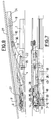
- the device is arranged on a pair of parallel guide rails 1, which are attached to the roof of a vehicle.
- a sliding element 2 slidably mounted, the rear end of the hinge pin 35 to one end a lever 3 is articulated.
- the lever 3 is at its other end at the hinge pin 36 articulated to a rod 10 which is slidable in a Guide track 24 of an upper guide 8 is mounted, which on the underside of a Cover 27 is attached.
- the pin 22 is slidably mounted in a slide track 23, which in one with the Guide rail 1 fixed link 4 is provided.
- the guideway 23 has a first sloping portion 23a and a second sloping portion inclined portion 23b.
- the front end of the rod 10 is pivotable at the hinge pin 37 to a first Front sliding element 9 articulated, which is also within the guide rail 1st is displaceable and which is flanked by a second front sliding element 5.
- the second sliding element 5 is also slidably mounted in the guide rail 1. It is also articulated by means of a lever 6 on a linkage 7, which with the top guide 8 is connected.
- the sliding elements 5 and 9 are by means of a T-shaped locking element 14 connected to each other.
- the locking element 14 is pivoted about a hinge pin 38 on the front sliding element 9 and engages with its lower end 15 in a corresponding recess 16 on the second front Sliding element 5 a.
- the upper end 30 of the locking element 14 is in sliding Contact on a wall of the guide rail 1.
- the front sliding elements 5 and 9 are in this position with the Guide rail 1 locked via a locking element 18, which is a first pivotable has mounted end which is articulated with a hinge pin 39 on the sliding element 5 is, and which has a second opposite end, which in a savings 19 engages in the guide rail 1.
- the locking element 18 is also with a bolt 40 provided which engages in an inclined slot 26 on a drive carriage 13.
- the drive carriage 13 is made in a conventional manner by means of a flexible spiral cable 12 moves, which is either manually or electrically driven.
- Movement of the drive cable 12 causes movement of the drive carriage 13.
- the drive carriage 13 is with the sliding element 2 through a locking element 20th (Fig. 1 and 4) connected, which is pivotable about a pivot axis 42 on Sliding element 2 is mounted and engages in a recess 21 on the drive carriage 13.
- a locking element 20th (Fig. 1 and 4) connected, which is pivotable about a pivot axis 42 on Sliding element 2 is mounted and engages in a recess 21 on the drive carriage 13.
- the drive carriage 13 moves to the right, it takes the locking element 20 and accordingly the sliding element 2 with it.
- an upper tongue 20a of the locking element 20 in sliding contact against a wall of the Guide rail 1 held because the force acting on the drive carriage 13 extends eccentrically with respect to the pivot axis 42 of the locking element 20.
- the upper end of the opening lever 3 lowers slightly while the pin 22 moves the downward sloping portion 23b of FIG Scenery path 23 passes.
- the sliding elements 5 and 9 continue to move towards the rear and the cover 27 is actuated further in the opening direction. If the pen 22 reaches the end of the slide track 23 (FIGS. 7 + 8), the locking element 20, the hitherto has coupled the sliding element 2 to the drive carriage 13, in engagement with a recess 28 of the guide rail and thereby comes from the recess 21 disengaged from the drive carriage 13.
Landscapes
- Engineering & Computer Science (AREA)
- Mechanical Engineering (AREA)
- Power-Operated Mechanisms For Wings (AREA)
- Support Devices For Sliding Doors (AREA)
- Body Structure For Vehicles (AREA)
- Seal Device For Vehicle (AREA)
Description
- Fig. 1
- eine Draufsicht einer erfindungsgemaßen Einrichtung, wie sie zu beiden Seiten einer Dachöffnung in einem Fahrzeugdach verwendet wird, in Schließposition,
- Fig. 2
- eine Seitenansicht der Einrichtung gemäß Pfeil A der Figur 1,
- Fig. 3
- einen Längsschnitt gemäß der Linie III-III der Fig. 1,
- Fig. 4
- eine Draufsicht auf die Einrichtung in einer ersten Öffnungsphase,
- Fig. 5
- eine Seitenansicht der Einrichtung gemäß dem Pfeil B der Fig. 4,
- Fig. 6
- einen Teillängsschnitt durch die Einrichtung gemäß der Linie VI-VI in Fig. 4,
- Fig. 7 + 8
- eine Draufsicht und eine Seitenansicht der Einrichtung in einer auf die Fig. 4 folgenden Öffnungsphase,
- Fig. 9 + 10
- eine Draufsicht und eine Seitenansicht der Einrichtung in der vollständigen Öffnungsposition und
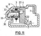
- Fig. 11
- einen Querschnitt gemäß der Linie C-C in den Fig. 2 und 3.
- 1
- Führungsschiene
- 2
- Gleitelement
- 3
- Ausstellhebel
- 4
- Kulisse (an 1)
- 5
- (zweites) Gleitelement
- 6
- Hebel (zwischen 5 und 7)
- 7
- Gestänge (an 8)
- 8
- Führung (am Deckel 27)
- 9
- (erstes) Gleitelement (vorderstes)
- 10
- Stange
- 12
- Antriebskabel
- 13
- Antriebsschlitten
- 14
- Riegelelement (zwischen 5 und 9)
- 15
- unteres Ende (von 14)
- 16
- Aussparung (an 5)
- 18
- Riegelelement
- 19
- Aussparung (in 1)
- 20
- Riegelelement
- 20A
- obere Zunge (von 20)
- 21
- Aussparung (an 13)
- 22
- Stift (an 3)
- 23
- Kulissenbahn
- 23a, b
- Kulissenbahn-Abschnitte
- 24
- Führungsbahn (an 8)
- 26
- Schlitz (an 13)
- 27
- Deckel
- 28
- Öffnung (in 1)
- 30
- oberes Ende (von 14)
- 31
- Aussparung (in 1)
- 32
- Gleitschuh (an 10)
- 33
- Nut (in 8)
- 35
- Gelenkbolzen (zwischen 2 und 3)
- 36
- Gelenkbolzen (zwischen 3 und 10)
- 37
- Gelenkbolzen (zwischen 9 und 10)
- 38
- Gelenkbolzen (für Riegelelement 14)
- 39
- Gelenkbolzen (für Riegelelement 18)
- 40
- Bolzen (an 18)
- 41
- Verzahnung (an 26)
- 42
- Schwenkachse (von 20)
Claims (9)
- Einrichtung zum Schließen oder wenigstens teilweisen Öffnen eines Deckels (27) eines Hebe-Schiebedachesmit einem Antriebsschlitten (13), der verschiebbar an dachfesten Führungsschienen (1) gelagert ist, der mit einem Ausstellhebel (3) zum Anheben oder Absenken des Deckels (27) in Verbindung steht und der mit Betätigungsmitteln (12) verbunden ist, dadurch gekennzeichnet,daß die Einrichtung wenigstens zwei Gleitelemente (2,5,9) umfaßt, die verschiebbar in den Führungsschienen (1) geführt sind und von denen wenigstens zwei Gleitelemente (2,5,9) mit Verriegelungsteilen (20,20A; 14,15,30; 18) zur Herstellung einer zeitweisen Verriegelung mit Aussparungen (28,31,19) an der Führungsschiene (1) oder zur zumindestens mittelbaren Verriegelung mit dem Antriebsschlitten (13) versehen sind unddaß an einem der Gleitelemente (9) ein Führungsorgan (Stange 10) angelenkt ist, an dem der Deckel (27) verschiebbar geführt ist.
- Einrichtung nach Anspruch 1, dadurch gekennzeichnet, daß die Gleitelemente (2,5,9) bei geschlossenem Deckel (27) einander benachbart im vorderen Teil der Führungsschienen (1) angeordnet sind.
- Einrichtung nach einem der vorhergehenden Ansprüche, dadurch gekennzeichnet, daß der Deckel (27) nahe seiner Vorderkante mit einem der Gleitelemente (5) schwenkbar verbunden ist.
- Einrichtung nach Anspruch 3, dadurch gekennzeichnet, daß die Verbindung zwischen dem Deckel (27) und dem Gleitelement (5) mittels eines Hebels (6) erfolgt.
- Einrichtung nach einem der vorhergehenden Ansprüche, dadurch gekennzeichnet, daß zwei in Schließposition des Deckels (27) vorn liegende Gleitelemente (5,9) während eines Teils der Verschiebebewegung des Deckels mittels eines Riegelelements (20) miteinander sowie zusätzlich mit dem Antriebsschlitten (13) gekoppelt sind.
- Einrichtung nach Anspruch 5, dadurch gekennzeichnet, daß vor Beendigung der Verschiebebewegung des Deckels (27) in Öffnungsrichtung eine Entkoppelung der Gleitelemente (5,9) erfolgt mit einer anschließenden Verriegelung des einen Gleitelements (9) mit der Führungsschiene.
- Einrichtung nach einem der vorhergehenden Ansprüche, dadurch gekennzeichnet, daß der Ausstellhebel (3) über einen Stift (22) mit einer dachfesten Kulisse (4) in Eingriff steht.
- Einrichtung nach Anspruch 7, dadurch gekennzeichnet, daß der Ausstellhebel (3) mit seinem unteren Ende (35) an ein zu Anfang der Verschiebebewegung des Deckels (27) in Öffnungsrichtung mit dem Antriebsschlitten (13) koppelbares Gleitelement (2) angelenkt ist und mit seinem oberen Ende (36) schwenkbar und längsverschiebbar am Führungsorgan (10) befestigt ist.
- Einrichtung gemäß wenigstens einem der vorhergehenden Ansprüche,
dadurch gekennzeichnet, daß die Einrichtung drei Gleitelemente (2, 5, 9) umfaßt, von denenein hinteres Gleitelement (2) mit dem unteren Ende des Ausstellhebels (3) verbunden ist und über ein Verriegelungsteil (20) während der Ausstellbewegung des Deckels (27) mit einer Aussparung (21) am Antriebsschlitten (13) und während der letzten Phasen der Verschiebebewegung des Deckels (27) mit einer Aussparung (28) der Führungsschiene (1) im Eingriff steht,ein erstes vorderes Gleitelement (9), an dem ein Führungsorgan (10) für den Deckel (27) angelenkt ist, und ein zweites vorderes Gleitelement (5) während der Ausstellbewegung des Deckels (27) mittels eines an einem der Gleitelemente (5) angeordneten Riegelelements (18) mit einer Aussparung (19) der Führungsschiene (1) im Eingriff stehen, ferner während dieser Ausstellphase und einem ersten Teil der Verschiebebewegung des Deckels (27) mittels eines Riegelelements (14) miteinander gekoppelt sind, sowie mit einem weiteren Riegelelement (40) mit dem Antriebsschlitten (13) in Verbindung stehen,das erste vordere Gleitelement (9) während der letzten Phase der Verschiebebewegung des Deckels (27) vom zweiten vorderen Gleitelement (5) abgekoppelt und gleichzeitig mittels des Riegelelements (14) mit einer Aussparung (31) der Führungsschiene (1) verriegelt wird, wobei das mit einem deckelfesten Teil (7) gekoppelte zweite Gleitelement (5) mit dem Antriebsschlitten (13) gekoppelt bleibt.
Applications Claiming Priority (2)
| Application Number | Priority Date | Filing Date | Title |
|---|---|---|---|
| ITTO930609 | 1993-08-11 | ||
| ITTO930609A IT1261560B (it) | 1993-08-11 | 1993-08-11 | Dispositivo per l'apertura e la chiusura di un tettuccio di automobile |
Publications (2)
| Publication Number | Publication Date |
|---|---|
| EP0638452A1 EP0638452A1 (de) | 1995-02-15 |
| EP0638452B1 true EP0638452B1 (de) | 1998-03-04 |
Family
ID=11411688
Family Applications (1)
| Application Number | Title | Priority Date | Filing Date |
|---|---|---|---|
| EP94112589A Expired - Lifetime EP0638452B1 (de) | 1993-08-11 | 1994-08-11 | Einrichtung zum Schliessen oder wenigstens teilweisen Öffnen eines Deckels eines Hebe-Schiebedaches |
Country Status (4)
| Country | Link |
|---|---|
| EP (1) | EP0638452B1 (de) |
| JP (1) | JP3410826B2 (de) |
| DE (1) | DE59405350D1 (de) |
| IT (1) | IT1261560B (de) |
Families Citing this family (21)
| Publication number | Priority date | Publication date | Assignee | Title |
|---|---|---|---|---|
| DE19828464C1 (de) * | 1998-06-26 | 1999-12-16 | Webasto Karosseriesysteme | Vorrichtung zur Betätigung eines Hebe-Schiebedaches |
| NL1011251C2 (nl) * | 1999-02-09 | 2000-08-10 | Inalfa Ind Bv | Open-dakcontructie voor een voertuig. |
| DE19940520C1 (de) * | 1999-08-26 | 2001-02-01 | Webasto Vehicle Sys Int Gmbh | Fahrzeugdach mit in eine geräuschoptimierte Ausstellposition betätigbarem Deckel |
| DE10140389C2 (de) * | 2001-08-23 | 2003-11-27 | Webasto Vehicle Sys Int Gmbh | Fahrzeugdach |
| DE10240636A1 (de) | 2002-09-03 | 2004-03-11 | Arvinmeritor Gmbh | Führungsmechanik für einen Deckel eines Schiebehebedachs |
| DE10354832A1 (de) | 2003-11-24 | 2005-06-23 | Arvinmeritor Gmbh | Verstellmechanik für ein Schiebe-/Hub-Dach |
| EP1741588B1 (de) * | 2005-07-08 | 2010-11-17 | Inalfa Roof Systems Group B.V. | Öffnungsfähige Dachkonstruktion für ein Fahrzeug |
| DE102005059287B4 (de) * | 2005-12-12 | 2007-10-18 | Webasto Ag | Fahrzeugdach mit wenigstens einem oberhalb eines festen Fahrzeugdachs verschiebbaren Deckel |
| DE602007009974D1 (de) * | 2007-08-09 | 2010-12-02 | Inalfa Roof Sys Group Bv | Schiebedachkonstruktion |
| DE102007061091A1 (de) | 2007-12-19 | 2009-06-25 | Arvinmeritor Gmbh | Schiebedachsystem für ein Kraftfahrzeug |
| DE102011015833B4 (de) * | 2011-04-01 | 2018-07-05 | Daimler Ag | Schiebedachsystem, insbesondere für ein Kraftfahrzeug |
| EP3176017B8 (de) * | 2015-12-04 | 2020-04-01 | Inalfa Roof Systems Group B.V. | Offene dachkonstruktion für ein fahrzeug |
| NL2018307B1 (en) * | 2017-02-03 | 2018-08-28 | Tenderworks B V | tiltable sliding roof for a vehicle |
| EP3552853B1 (de) | 2018-04-12 | 2021-01-27 | Inalfa Roof Systems Group B.V. | Sonnendach system für ein fahrzeug mit rotierendem schlitten |
| EP3647094B1 (de) | 2018-11-05 | 2022-10-26 | Inalfa Roof Systems Group B.V. | Dachsystem für ein fahrzeug |
| DE102019200264A1 (de) * | 2019-01-11 | 2020-07-16 | Bos Gmbh & Co. Kg | Antriebssystem für ein Spoilerdachsystem eines Kraftfahrzeugs |
| US10946732B2 (en) | 2019-03-18 | 2021-03-16 | AISIN Technical Center of America, Inc. | Tilt and outer slide system for panoramic sunroofs |
| EP3792091B1 (de) | 2019-09-10 | 2022-06-15 | Inalfa Roof Systems Group B.V. | Dachanordnung für ein fahrzeug und verfahren zur montage |
| DE102019135699B4 (de) * | 2019-12-23 | 2026-03-05 | Webasto SE | Fahrzeugdach, umfassend ein Dachöffnungssystem mit zwei Kinematikeinheiten |
| EP4019306B1 (de) * | 2020-12-22 | 2024-03-13 | Inalfa Roof Systems Group B.V. | Offene dachkonstruktion für ein fahrzeug |
| DE102022130019A1 (de) * | 2022-11-14 | 2024-05-16 | Webasto SE | Anordnung für ein Fahrzeugdach und Fahrzeugdach |
Family Cites Families (3)
| Publication number | Priority date | Publication date | Assignee | Title |
|---|---|---|---|---|
| JPS596127A (ja) * | 1982-07-02 | 1984-01-13 | Honda Motor Co Ltd | 車両用摺動式屋根構造 |
| FR2587657B1 (fr) * | 1985-09-26 | 1989-09-29 | Farnier & Penin | Dispositif de toit ouvrant pour pavillon de vehicule automobile |
| DE3735686C1 (de) * | 1987-10-22 | 1988-12-08 | Webasto Ag Fahrzeugtechnik | Fahrzeugdach |
-
1993
- 1993-08-11 IT ITTO930609A patent/IT1261560B/it active IP Right Grant
-
1994
- 1994-07-21 JP JP16981994A patent/JP3410826B2/ja not_active Expired - Fee Related
- 1994-08-11 DE DE59405350T patent/DE59405350D1/de not_active Expired - Fee Related
- 1994-08-11 EP EP94112589A patent/EP0638452B1/de not_active Expired - Lifetime
Also Published As
| Publication number | Publication date |
|---|---|
| ITTO930609A0 (it) | 1993-08-11 |
| ITTO930609A1 (it) | 1995-02-11 |
| DE59405350D1 (de) | 1998-04-09 |
| JP3410826B2 (ja) | 2003-05-26 |
| JPH07149152A (ja) | 1995-06-13 |
| IT1261560B (it) | 1996-05-23 |
| EP0638452A1 (de) | 1995-02-15 |
Similar Documents
| Publication | Publication Date | Title |
|---|---|---|
| EP0638452B1 (de) | Einrichtung zum Schliessen oder wenigstens teilweisen Öffnen eines Deckels eines Hebe-Schiebedaches | |
| EP1172243B1 (de) | Fahrzeugdach mit wenigstens einem oberhalb des festen Fahrzeugsdachs verschiebbaren Deckel | |
| DE3442631C2 (de) | ||
| EP0727331B1 (de) | Fahrzeugdach mit zwei Deckelelementen | |
| DE3735686C1 (de) | Fahrzeugdach | |
| DE3816977C2 (de) | ||
| DE102005007031B4 (de) | Fahrzeugdach mit einem oberhalb des Daches verschiebbaren Dachteil | |
| DE3416176A1 (de) | Fahrzeugschiebedach | |
| DE4407286C1 (de) | Fahrzeugdach mit einer Folge von Lamellen | |
| DE19700165C2 (de) | Schiebehebedach | |
| DE69915122T2 (de) | Konstruktion eines öffnungsfähigen fahrzeugdaches | |
| EP1223065A1 (de) | Fahrzeugdach | |
| DE10333781B4 (de) | Öffnungsfähiges Fahrzeugdach | |
| EP0747251A1 (de) | Windabweiser | |
| DE4127624C1 (de) | ||
| DE10046068A1 (de) | Öffnungsfähiges Fahrzeugdach | |
| DE102006062543B4 (de) | Fahrzeugdach mit einem oberhalb des Daches verschiebbaren Dachteil | |
| EP0967099A2 (de) | Vorrichtung zur Bestätigung eines Hebe-Schiebedaches | |
| DE60213202T2 (de) | Öffnungsfähige Dachkonstruktion für ein Fahrzeug und Verfahren für die Betätigung eines zugehörigen Schliesselementes | |
| DE3416485C2 (de) | Ausstelldach für ein Fahrzeug | |
| DE10158174B4 (de) | Schiebehebedach für Fahrzeuge | |
| DE10065947C2 (de) | Öffnungsfähiges Fahrzeugdach | |
| DE19634324C2 (de) | Fahrzeugdach | |
| DE4001759C1 (en) | Sun roof for motor vehicles - has lever pivoting at end of sliding guide to actuate roof panel | |
| DE4329580C1 (de) | Fahrzeugdach mit einer Folge von Lamellen |
Legal Events
| Date | Code | Title | Description |
|---|---|---|---|
| PUAI | Public reference made under article 153(3) epc to a published international application that has entered the european phase |
Free format text: ORIGINAL CODE: 0009012 |
|
| AK | Designated contracting states |
Kind code of ref document: A1 Designated state(s): DE FR GB NL |
|
| 17P | Request for examination filed |
Effective date: 19950607 |
|
| 17Q | First examination report despatched |
Effective date: 19960917 |
|
| GRAG | Despatch of communication of intention to grant |
Free format text: ORIGINAL CODE: EPIDOS AGRA |
|
| GRAH | Despatch of communication of intention to grant a patent |
Free format text: ORIGINAL CODE: EPIDOS IGRA |
|
| GRAH | Despatch of communication of intention to grant a patent |
Free format text: ORIGINAL CODE: EPIDOS IGRA |
|
| GRAA | (expected) grant |
Free format text: ORIGINAL CODE: 0009210 |
|
| AK | Designated contracting states |
Kind code of ref document: B1 Designated state(s): DE FR GB NL |
|
| GBT | Gb: translation of ep patent filed (gb section 77(6)(a)/1977) |
Effective date: 19980305 |
|
| REF | Corresponds to: |
Ref document number: 59405350 Country of ref document: DE Date of ref document: 19980409 |
|
| ET | Fr: translation filed | ||
| PLBE | No opposition filed within time limit |
Free format text: ORIGINAL CODE: 0009261 |
|
| STAA | Information on the status of an ep patent application or granted ep patent |
Free format text: STATUS: NO OPPOSITION FILED WITHIN TIME LIMIT |
|
| 26N | No opposition filed | ||
| REG | Reference to a national code |
Ref country code: GB Ref legal event code: IF02 |
|
| PGFP | Annual fee paid to national office [announced via postgrant information from national office to epo] |
Ref country code: GB Payment date: 20030806 Year of fee payment: 10 |
|
| PGFP | Annual fee paid to national office [announced via postgrant information from national office to epo] |
Ref country code: FR Payment date: 20030808 Year of fee payment: 10 |
|
| PGFP | Annual fee paid to national office [announced via postgrant information from national office to epo] |
Ref country code: NL Payment date: 20030831 Year of fee payment: 10 |
|
| PG25 | Lapsed in a contracting state [announced via postgrant information from national office to epo] |
Ref country code: GB Free format text: LAPSE BECAUSE OF NON-PAYMENT OF DUE FEES Effective date: 20040811 |
|
| PG25 | Lapsed in a contracting state [announced via postgrant information from national office to epo] |
Ref country code: NL Free format text: LAPSE BECAUSE OF NON-PAYMENT OF DUE FEES Effective date: 20050301 |
|
| GBPC | Gb: european patent ceased through non-payment of renewal fee |
Effective date: 20040811 |
|
| PG25 | Lapsed in a contracting state [announced via postgrant information from national office to epo] |
Ref country code: FR Free format text: LAPSE BECAUSE OF NON-PAYMENT OF DUE FEES Effective date: 20050429 |
|
| NLV4 | Nl: lapsed or anulled due to non-payment of the annual fee |
Effective date: 20050301 |
|
| REG | Reference to a national code |
Ref country code: FR Ref legal event code: ST |
|
| PGFP | Annual fee paid to national office [announced via postgrant information from national office to epo] |
Ref country code: DE Payment date: 20080821 Year of fee payment: 15 |
|
| PG25 | Lapsed in a contracting state [announced via postgrant information from national office to epo] |
Ref country code: DE Free format text: LAPSE BECAUSE OF NON-PAYMENT OF DUE FEES Effective date: 20100302 |