EP0638682B1 - Machine à broder à navettes avec un dispositif coupe-fil - Google Patents
Machine à broder à navettes avec un dispositif coupe-fil Download PDFInfo
- Publication number
- EP0638682B1 EP0638682B1 EP94810462A EP94810462A EP0638682B1 EP 0638682 B1 EP0638682 B1 EP 0638682B1 EP 94810462 A EP94810462 A EP 94810462A EP 94810462 A EP94810462 A EP 94810462A EP 0638682 B1 EP0638682 B1 EP 0638682B1
- Authority
- EP
- European Patent Office
- Prior art keywords
- embroidering machine
- knife
- thread
- rails
- lever
- Prior art date
- Legal status (The legal status is an assumption and is not a legal conclusion. Google has not performed a legal analysis and makes no representation as to the accuracy of the status listed.)
- Expired - Lifetime
Links
- 238000005520 cutting process Methods 0.000 title claims abstract description 91
- 238000009956 embroidering Methods 0.000 title claims abstract description 19
- 239000004744 fabric Substances 0.000 claims description 6
- 238000006073 displacement reaction Methods 0.000 description 4
- 238000010276 construction Methods 0.000 description 3
- 230000000694 effects Effects 0.000 description 2
- 238000000034 method Methods 0.000 description 2
- 241000985128 Cladium mariscus Species 0.000 description 1
- 229910000639 Spring steel Inorganic materials 0.000 description 1
- 238000005299 abrasion Methods 0.000 description 1
- 230000008878 coupling Effects 0.000 description 1
- 238000010168 coupling process Methods 0.000 description 1
- 238000005859 coupling reaction Methods 0.000 description 1
- 210000005069 ears Anatomy 0.000 description 1
- 230000001771 impaired effect Effects 0.000 description 1
- 238000012423 maintenance Methods 0.000 description 1
- 239000000463 material Substances 0.000 description 1
- 239000002184 metal Substances 0.000 description 1
- 238000004080 punching Methods 0.000 description 1
- 238000009958 sewing Methods 0.000 description 1
- 239000004753 textile Substances 0.000 description 1
Images

Classifications
-
- D—TEXTILES; PAPER
- D05—SEWING; EMBROIDERING; TUFTING
- D05C—EMBROIDERING; TUFTING
- D05C11/00—Devices for guiding, feeding, handling, or treating the threads in embroidering machines; Machine needles; Operating or control mechanisms therefor
- D05C11/20—Arrangements for cutting the needle or lower threads
Definitions
- the present invention relates to a shuttle embroidery machine with shuttle tracks arranged on a profile, which are delimited on the fabric side by a stitch plate, and a thread cutting device for the rear thread with a knife, which can be positioned by a mechanism in front of the stitch plate for a cutting process.
- the Swiss patent specification CH 660 608 discloses an embroidery machine in which a coupling is provided at each individual embroidery point in the drive train for the driver rod for the switching on and off of the respective embroidery point which can be influenced independently.
- the thread is behind the needle plate automatically cut by a thread cutter.
- This device has the disadvantage that a separate drive is assigned to each individual thread clamping and cutting device and this requires a large amount of space. For this reason, this device cannot be used on every shuttle embroidery machine.
- the thread previously clamped for cutting can be released again after cutting, so that damage to the latter can occur during further operation.
- a thread clamping and cutting device for the back or under thread of an embroidery machine is disclosed, which is arranged in the area of the stitch hole and also cuts the thread behind the stitch plate.
- the clamping gap of the thread clamping device is arranged in alignment with the cutting device.
- This device is characterized in that an intermediate plate with slot-shaped recesses is mounted on the throat plate, into which a guide part can be inserted.
- the guide part has an inner recess in which an actuating slide is slidably guided.
- the actuating slide itself has a U-shaped profile, in which the guide part engages with a projection, so that the actuating slide is guided.
- the actuating slide is screwed to an actuating rod which can be moved back and forth by a sliding drive.
- Two keyhole-shaped recesses are aligned in the U-profile, which are at the height of the stitch hole when embroidering.
- the lower boundary of the front keyhole-shaped recess is designed as a cutting edge.
- the counter knife is clipped in place in the guide part above the tap hole.
- the clamping gap is formed by a resiliently mounted clamping finger in the guide part and a counter-clamping piece inserted in the guide part. Due to the construction described, the thread is first clamped in the clamping gap during the cutting process and then cut.
- Another advantage is that the thread remains clamped in the clamping gap even after the actuating slide has been retracted, and only then is relieved by sufficient tension from the nip when re-stitching.
- the cutting and clamping device described also clamps the thread after the cutting process and is extremely space-saving.
- the cutting and clamping device is relatively complex, complicated and therefore expensive.
- the sliding mechanism is contaminated by external influences or by abrasion and this can lead to longer downtimes.
- GB-A-12 185 discloses a thread clamping and cutting device for the rear thread of a shuttle embroidery machine which is arranged during embroidery below the carrier rail which carries the shuttle and the associated drive.
- This device has a shaft which is rotatable and displaceable in the longitudinal direction.
- a crank is arranged on the shaft, which carries a rail which can extend along the entire embroidery machine.
- a plate is also attached to the rail, which has cutting surfaces on the upper edge.
- the carrier rail with the shuttle is pulled back a little to create a space between the embroidered fabric and the needle plate. Then the shaft of the thread clamping and cutting device is shifted and rotated in the longitudinal direction, whereby the plate is pivoted in front of the needle plate and strikes it.
- the plate During the upward movement, the plate hits the rear thread, clamps it onto the needle plate and cuts it off.
- the thread is clamped during the cutting process and remains clamped even after cutting so that it can be sewn on again.
- the device described has the disadvantage that it is not possible to cut the rear thread without prior clamping, since otherwise the thread would be pulled out of the shuttle by the simple knife movement.
- the needle hole cannot act as a counter knife, since the edges of the needle hole must be rounded in order to avoid inadvertent chafing or cutting off of the rear thread during embroidery.
- the cutting device should be robust, easily accessible, easy to service and insensitive to dirt. It would also be an advantage if embroidery or sewing machines already in use could also be inexpensively retrofitted with the cutting device.
- the knife has a guide element and that the mechanism ensures a relative movement of the knife and guide element for cutting the thread.
- the knife and the guide element virtually perform a scissor movement when cutting, i.e. the cutting surface of the knife crosses or intersects with an edge of the guide element.
- This type of cutting movement of the knife and guide element means that the thread is not stressed during cutting and there is no danger that it would be pulled out of the shuttle. For this reason, thread clamping can be dispensed with, e.g. is necessary if the thread is to be cut off at the tap hole (see GB-A-12 185). In contrast to DE-OS-2 065 264, no gripper is needed to grasp the thread to be cut.
- the solution according to the invention is therefore simple, robust and inexpensive.
- Another advantage is that the thread cutting device works independently, i.e. that these e.g. is not coupled with the decommissioning of boats as described in CH 660 608. As a result, the rear thread can be cut off without the associated shuttle being shut down for further operation at the same time. Moving the knife enables the thread to be cut in front of the stitch plate and close to the embroidery site.
- An edge of the guide element is expediently designed as a cutting edge, which can interact with the cutting edge of the knife. Because the thread is cut by two intersecting cutting surfaces, thin ones can also be cut Threads of whatever material are reliably cut.
- the knives and the guide elements are advantageously detachably attached to rails. This is particularly advantageous because the actuating mechanism then only has to ensure a relative movement of the rails. As a result, a large number of knives can be actuated with just one drive, which considerably simplifies the construction. It is also advantageous if the knives and the guide elements are formed in blocks on a knife rail or. are combined into a guide plate. These can be changed quickly if necessary, for example to sharpen the cutting edges.
- the knives are expediently connected to the mechanism in such a way that when the same is actuated, both a displacement of the knives along at least one axis and a relative movement of the same results.
- This can e.g. by means of a suitable eccentric device or a lever arrangement which positions the knives in front of the throat plate and at the same time ensures a scissor movement of the knives.
- the cutting device can be arranged below the angle profile or at another location on the embroidery machine.
- the mechanism advantageously has at least one pivotable lever which connects the rails in an articulated manner.
- the two rails can be moved apart like scissors by the lever.
- Another advantageous construction provides that the rails are connected to one another by means of two levers arranged one behind the other, a lever which is articulated on one rail and an angle lever which is articulated at its angle on the other rail.
- the angle lever can have two arms of different lengths, so that a large lever effect can be generated.
- the actuating mechanism advantageously has a drive shaft which is connected in a rotationally fixed manner to a further lever. The free end of this lever is articulated to a lever already described above, which is required for the relative movement of the two rails.
- the rotation of the drive shaft can a vertical displacement of the rails can be effected at the same time.
- the drive shaft in order to generate a feed movement, is connected in a rotationally fixed manner to a link having a curve, the link interacting with a stationary part.
- a translatory movement of the shaft can be generated simultaneously by a rotary movement.
- the knife can thus be moved when cutting onto the fabric stretched on the creel, and the thread can be cut off directly at the embroidery site.
- the backdrop is advantageously cylindrical and has a curved channel milled into the lateral surface. A stationary bolt can protrude into this channel, so that when the link is rotated it is moved in the longitudinal direction.
- the knife expediently has a hook-shaped cutting edge which cooperates with the upper edge of the guide plate designed as a counter knife during thread cutting. Thanks to the two cutting edges, the thread can be cut cleanly.
- the knife has a straight cutting edge which is at an angle to the upper edge of the guide part.
- the angle between the cutting edge and the upper edge of the guide plate can be between approximately 4 and 45 °, preferably approximately 5 to 25 °.
- the thread to be cut can be easily positioned under the cutting edge and the result is a scissor movement that promotes cutting.
- Another advantage is that the deflection of the knife needs to be less than e.g. when using hook-shaped cutting edges.
- Guides are preferably provided on the guide plate, which connect the knife bar and the guide plate. This ensures tight guidance of the knives on the guide plates.
- the knives and the guide plates can be pretensioned, ie slightly curved. This feature ensures that the cutting edge of the knife the upper edge of the guide plate, which is designed as a counter knife, can interact optimally.
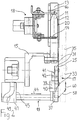
- Figures 1 and 2 show a thread cutting device 17 and upwardly projecting shuttle webs 13 of a shuttle embroidery machine.
- the shuttle tracks 13 are screwed to an angular profile 15, the so-called Stöcklilineal.
- the shuttle lanes 13 are each delimited by the throat plate 12.
- the shuttle 11 move up and down during the embroidery process.
- the boats 11 are held or driven by the driver nails 14, 16, which are arranged on the movable oscillating beam 18.
- the shuttle 11 are looped through the upper or front thread carried out, which is brought by means of the embroidery needle through the tap hole 20 in the shuttle 13.
- the thread cutting device 17 already mentioned, which is shown in FIG. 1 in two different positions.
- the representation at the edge of the drawing shows the thread cutting device 17 in the rest position; the other illustration shows the thread cutting device 17 in the cutting position.
- the cutting position is shown in dashed lines in FIG.
- the cutting device can be displaced along two axes (arrows 58, 60).
- the thread cutting device 17 is in the rest position approximately in the plane of the needle plate 12.
- the device in front of the needle plate 12 or. positioned on the embroidered fabric so that the thread can be cut as close as possible to the embroidery site.
- the thread cutting device 17 comprises an actuating mechanism 19 and a plurality of knives 21 arranged at a distance from the stitch holes 20.
- a plurality of knives 21 can be formed on a single sheet and form a knife rail 31 (FIG. 1).
- the knives 21 are guided by a guide plate 25.
- the guide plate 25 has punched-out ears 27 projecting from the surface, by means of which the shank of the knives 21 is guided in each case.
- a large number of knife rails 31 and guide plates 25 each work in pairs and are detachably fastened to rails 33, 35.
- the rails 33, 35 can be moved relative to one another by the mechanism 19 and can be positioned in front of the throat plate 12.
- the knife rails 31 and guide plates 25 shown can be produced simply, for example by punching them out of a metal sheet. They advantageously consist of a thin spring steel sheet.
- the knives 21 run parallel to the shuttle tracks 13 and have a hook-shaped cutting edge 23.
- the upper edge 29 of the guide element 25 is also designed as a cutting edge, which is each provided with a knife 21 cooperates.
- the knife rails 31 and / or the guide plates 25 are expediently prestressed against one another, ie are slightly concave. This ensures that the cutting edges 23, 29 run closely together.
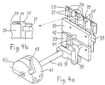
- the knives 21 ′ according to FIG. 4 have approximately straight cutting edges 24 instead of the hook-shaped cutting edges 23, which are at a certain angle to the upper edges of the guide plates 25.
- This design of the cutting edges 24 has the advantage that the thread to be cut can be positioned particularly easily under the cutting edge 24. It has proven to be advantageous if the cutting edges 24 are at an angle between approximately 5 and 25 ° to the upper edge 29 of the guide plate 25.
- the knives 21, 21 ' can be positioned in front of the throat plate 12 for cutting.
- the structural details of a preferred embodiment, which can cause the displacement and the actual cutting movement of the knives, are discussed in more detail below.
- the rails 33, 35 carrying the knife rails 31 and the guide plates 25 must be moved relative to one another in such a way that the cutting edges of the knives 21 and the upper edge 29 of the guide plate 25 can overlap.
- the knife rail 31 is releasably attached to the rail 35.
- the guide plate 25, however, is releasably attached to the rail 33.
- the rails 33, 35 are articulated to one another with two levers 39, 41.
- the lever 41 is articulated at one end to a pin 42 arranged on the rail 35.
- the lever 39 is designed as an angle lever and is articulated at an angle on a pin 40 of the rail 33.
- a pivoting of the angle lever 39 has the effect that the two rails 33, 35, which are perpendicular to their longitudinal extension (not shown), are deflected relative to one another (FIG. 1).
- a drive shaft 43 is provided, which is connected in a rotationally fixed manner to a lever 37.
- the lever 37 is articulated on the angle lever 39 at the other end.
- the guided rails 33, 35 are moved upward, as shown in FIG.
- This arrangement therefore has the advantage that not only is a relative movement of the rails 33, 35 produced by rotating the drive shaft 43, but they are simultaneously displaced a certain distance.
- the rails 33, 35 can be raised to approximately the height of the tap hole 20 (FIG. 1).
- a cylindrical link 45 is provided in order to move the cutting device 17, which in a preferred embodiment is in the plane of the throat plate 12 (FIG. 2) or behind it, in front of the throat plate 12, a cylindrical link 45 is provided. This is firmly connected to the drive shaft 43. A curved channel 49 is milled out in the lateral surface 47 of the backdrop 45. A fixed pin (not shown), which can be arranged on the profile 15, engages in this channel 49.
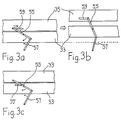
- FIG. 3 Further possible designs for generating the deflection of the rails 33, 35 and the relative movement thereof are shown schematically in FIG. 3.
- a straight lever 55 is articulated on the rail 33 approximately in the middle.
- One end of the lever 55 is guided in a slot 59 in the rail 35, the other end of the lever 55 is articulated on a lever 57.
- the rails 33, 35 are inevitably shifted upward.
- the rails 33, 35 perform a scissor movement (FIG. 3b).
- the rails 33, 35 are guided by suitable means in such a way that they can only be displaced perpendicularly to their longitudinal extent.
- 3 c shows a further exemplary embodiment for generating the deflection of the rails 33, 35 and the cutting movement.
- the lever 55 has a pin approximately in the middle, which is slidably guided in a slot 59 'in the rail 33. Furthermore, one end of the lever 55 is articulated on the rail 35, the other end on the lever 57. Analogously to the example of FIGS. 3 a, b, the rails 33, 35 can be deflected by pivoting the lever 57 and moved relative to one another.
- the thread cutting works as follows: When the shaft 43 is rotated by drive means (not shown in more detail), the entire drive shaft 43 moves with the rails 33, 35 as a function of the curve 49 of the link 45 along its longitudinal axis (FIG. 1: arrow 44). At the same time, the rails 33, 35 are moved up and apart due to the lever arrangement 37, 39, 41. The movement of the rails 33, 35 takes place along the arrows 58, 60 (FIG. 2). The last part of the movement is only in one direction (vertical). During this last part of the movement, the rails 33, 35 move apart, so that the cutting edges 23 of the knives 21 are moved beyond the upper edge 29 of the guide plate 25, i.e.
- Figure 2 position shown in dashed lines.
- the knife 21 is located in front of the stitch plate 12 in the area of the stitch hole 20.
- the gate with the stretched fabric is then moved so that the thread, which extends from the last embroidery point through the stitch hole 20 to the boat, comes to rest under the cutting edge 23.
- the link 45 is turned back until the cutting edges 23 and the edge 29 intersect and cut the thread (Fig. 2: movement of the rails against arrow 60). This cutting movement can be repeated by rotating the shaft 43 back and forth two or three times. This can ensure that all threads are cut.
- the length of the thread to be cut can be selected so that it can just be re-stitched on, but after the stitching there is no annoying thread at the new embroidery site.
- This has the advantage of being an additional one Device for clamping the thread, as mentioned, for example, in the writings cited at the beginning, can be dispensed with.
Landscapes
- Engineering & Computer Science (AREA)
- Textile Engineering (AREA)
- Sewing Machines And Sewing (AREA)
Claims (15)
- Machine à broder à navettes, comportant des coursières de navette qui sont disposées sur un profilé (15) et qui sont limitées du côté du tissu par une plaque à aiguilles, et un dispositif coupe-fil (17) pour le fil de derrière, avec un couteau (21) qui peut être place devant la plaque à aiguilles par un mécanisme (19) pour un processus de coupe, caractérisée en ce que le couteau (21) comporte un élément de guidage (25) et en ce que, pour la coupe du fil, le mécanisme (19) produit un mouvement relatif du couteau (21) et de l'élément de guidage (25).
- Machine à broder selon la revendication 1, caractérisée en ce qu'un bord (29) de l'élément de guidage (25) est réalisé sous forme de tranchant qui coopère avec le tranchant (23) du couteau (21).
- Machine à broder selon la revendication 1 ou 2, caractérisée en ce que les couteaux (21) et les éléments de guidage (25) sont fixés de façon amovible à des rails (35,33).
- Machine à broder selon l'une quelconque des revendications 1 à 3, caractérisée en ce que plusieurs couteaux (21) et plusieurs éléments de guidage sont respectivement réalisés sous forme de bloc sur un rail porte-couteaux (31) et réunis en une plaque de guidage (25).
- Machine à broder selon l'une quelconque des revendications 1 à 4, caractérisée en ce que les couteaux (21) sont reliés au mécanisme (19) de telle sorte que, lors de l'actionnement de celui-ci, il se produise à la fois un déplacement des couteaux (21) le long d'un axe (60) au moins et un mouvement relatif de ces derniers.
- Machine à broder selon la revendication 5, caractérisé en ce que le mécanisme comporte au moins un levier (55) qui relie les rails (33,35) de façon articulée et qui peut pivoter.
- Machine à broder selon la revendication 5 ou 6, caractérisée en ce que les rails (33,35) sont reliés l'un à l'autre au moyen de deux leviers (41,39) disposés à la suite l'un de l'autre, à savoir un levier (41) qui est articulé sur le rail (35) et un levier coudé (39) qui est articulé sur le rail (33) à l'endroit de son coude.
- Machine à broder selon l'une quelconque des revendications 5 à 7, caractérisée en ce que le mécanisme d'actionnement (19) comporte un arbre d'entraînement (43) qui est raccordé rigidement à un levier (57) de façon à ce qu'ils soient solidaires en rotation, levier dont l'autre extrémité est articulée sur le levier (39,55).
- Machine à broder selon l'une quelconque des revendications 5 à 8, caractérisée en ce que, pour la création d'un mouvement d'avance, l'arbre d'entraînement (43) est raccordé rigidement à une coulisse (45) de façon à ce qu'ils soient solidaires en rotation, laquelle coulisse présente une came (49), et en ce que la coulisse (45) coopère avec une pièce fixe.
- Machine à broder selon la revendication 9, caractérisée en ce que la coulisse (45) est cylindrique et présente une rainure courbe (49) qui est fraisée dans sa surface périphérique (47) et dans laquelle s'engage une cheville fixe (51).
- Machine à broder selon l'une quelconque des revendications 1 à 10, caractérisée en ce que le couteau (21) présente un tranchant (23) en forme de crochet.
- Machine à broder selon l'une quelconque des revendications 1 à 10, caractérisée en ce que le couteau (21) présente un tranchant rectiligne (24) qui forme un angle avec le bord supérieur (29).
- Machine à broder selon l'une quelconque des revendications 4 à 12, caractérisée en ce qu'il est prévu, sur la plaque de guidage (25), des guides (27) qui unissent le rail porte-couteaux (31) et la plaque de guidage (25).
- Machine à broder selon l'une quelconque des revendications 4 à 13, caractérisée en ce que le rail porte-couteaux (31) et la plaque de guidage (25) sont précontraints.
- Machine à broder selon l'une quelconque des revendications 1 à 14, caractérisée en ce que le dispositif coupe-fil (17) est monté sur le profilé (15).
Applications Claiming Priority (2)
| Application Number | Priority Date | Filing Date | Title |
|---|---|---|---|
| CH2452/93 | 1993-08-10 | ||
| CH245293 | 1993-08-10 |
Publications (2)
| Publication Number | Publication Date |
|---|---|
| EP0638682A1 EP0638682A1 (fr) | 1995-02-15 |
| EP0638682B1 true EP0638682B1 (fr) | 1995-09-20 |
Family
ID=4234151
Family Applications (1)
| Application Number | Title | Priority Date | Filing Date |
|---|---|---|---|
| EP94810462A Expired - Lifetime EP0638682B1 (fr) | 1993-08-10 | 1994-08-09 | Machine à broder à navettes avec un dispositif coupe-fil |
Country Status (3)
| Country | Link |
|---|---|
| EP (1) | EP0638682B1 (fr) |
| AT (1) | ATE128198T1 (fr) |
| DE (1) | DE59400017D1 (fr) |
Cited By (1)
| Publication number | Priority date | Publication date | Assignee | Title |
|---|---|---|---|---|
| WO2017190862A1 (fr) | 2016-05-03 | 2017-11-09 | Lässer Ag | Procédé d'actionnement d'un dispositif de coupe de fil et de serrage de fil pour la coupe du fil de navette sur une machine à broder de grande taille, et dispositif d'actionnement de l'ensemble de coupe de fil pour la mise en oeuvre de ce procédé |
Families Citing this family (4)
| Publication number | Priority date | Publication date | Assignee | Title |
|---|---|---|---|---|
| JP4530526B2 (ja) * | 2000-12-07 | 2010-08-25 | Juki株式会社 | 糸切り装置 |
| EP1460161B1 (fr) * | 2003-03-21 | 2008-04-09 | Franz Lässer AG | Dispositif pour couper le fil arrière dans des machines à broder à navette |
| DE102009060603B4 (de) * | 2009-12-23 | 2014-05-22 | Saurer Ag | Vorrichtung zur Einstellung der Wagenweite an einer Stickmaschine |
| CN115385485B (zh) * | 2022-09-19 | 2023-12-12 | 四川发展环境科学技术研究院有限公司 | 一种煤化工废水环保处理系统及处理方法 |
Family Cites Families (3)
| Publication number | Priority date | Publication date | Assignee | Title |
|---|---|---|---|---|
| DE2065264C3 (de) * | 1970-04-10 | 1975-09-25 | Rudolf 5450 Neuwied Reich | Fadenfang- und Schneidvorrichtung für den Schiffchenfaden einer Schiffchen-Stickmaschine |
| DE3133333C2 (de) * | 1981-08-22 | 1986-08-14 | Aktiengesellschaft Adolph Saurer, Arbon | Schiffchenstickmaschine |
| DE4202891A1 (de) * | 1991-11-08 | 1993-05-19 | Saurer Sticksysteme Ag | Fadenklemm- und schneideinrichtung fuer den hinten- oder unterfaden einer stickmaschine |
-
1994
- 1994-08-09 AT AT94810462T patent/ATE128198T1/de active
- 1994-08-09 EP EP94810462A patent/EP0638682B1/fr not_active Expired - Lifetime
- 1994-08-09 DE DE59400017T patent/DE59400017D1/de not_active Expired - Lifetime
Cited By (1)
| Publication number | Priority date | Publication date | Assignee | Title |
|---|---|---|---|---|
| WO2017190862A1 (fr) | 2016-05-03 | 2017-11-09 | Lässer Ag | Procédé d'actionnement d'un dispositif de coupe de fil et de serrage de fil pour la coupe du fil de navette sur une machine à broder de grande taille, et dispositif d'actionnement de l'ensemble de coupe de fil pour la mise en oeuvre de ce procédé |
Also Published As
| Publication number | Publication date |
|---|---|
| ATE128198T1 (de) | 1995-10-15 |
| EP0638682A1 (fr) | 1995-02-15 |
| DE59400017D1 (de) | 1995-10-26 |
Similar Documents
| Publication | Publication Date | Title |
|---|---|---|
| EP0082538B1 (fr) | Métier à tricoter pour la fabrication de peluche à poil coupé | |
| EP2336413B1 (fr) | Machine à broder à blocs à aiguilles multiples, bloc à aiguilles multiples pour cette machine, ainsi qu'élément coupe fil et coupe-fil pour cette machine | |
| DE19722504C1 (de) | Nähmaschine, insbesondere Knopfloch-Nähmaschine, mit einer Nadelfaden-Klemm- und- Schneid-Einrichtung | |
| DE2130642B2 (fr) | ||
| DE102007014547B4 (de) | Einfassmaschine | |
| DE19916660C1 (de) | Knopfloch-Nähmaschine | |
| EP0638682B1 (fr) | Machine à broder à navettes avec un dispositif coupe-fil | |
| DE7525743U (de) | Einrichtung zum herstellen von paspeloeffnungen in zuschnitteilen von bekleidungsstuecken | |
| EP0541923B1 (fr) | Coupe-fil avec pince-fil pour le fil arrière ou le fil du dessous d'une machine à broder | |
| EP0768418B1 (fr) | Machine à broder, en particulier de type Schiffli, avec un dispositif pour sectionner et pincer le fil de face | |
| EP0606585B1 (fr) | Dispositif pour sectionner et pincer le fil de face dans des machines à broder | |
| EP0638681B1 (fr) | Machine à broder à navettes | |
| DE4436613C1 (de) | Fadenabschneidvorrichtung | |
| DE1945310A1 (de) | Vorrichtung zum Durchtrennen der Fadenkette an Naehmaschinen | |
| EP3452653B1 (fr) | Procédé d'actionnement d'un dispositif coupe-fil et blocage du fil pour couper le fil de navette d'une grande machine à broder et dispositif d'actionnement du dispositif de coupe pour la mise en oeuvre du procédé | |
| DE3020279A1 (de) | Fadenabschneidvorrichtung fuer eine zweinadelnaehmaschine | |
| EP2360305B1 (fr) | Procédé de commande d'une machine à coudre et machine à coudre | |
| DE1585487C (de) | Flache Kulierwirkmaschine System Cotton | |
| DE2154361C2 (de) | Vielnadeldoppelkettenstichmaschine | |
| EP1460161B1 (fr) | Dispositif pour couper le fil arrière dans des machines à broder à navette | |
| DE2357605A1 (de) | Stoffbeschneidvorrichtung fuer naehmaschinen | |
| DE47033C (de) | Nähmaschine mit Vorrichtung zum Abschneiden überstehender Stoffkanten | |
| CH702471A1 (de) | Mehrnadelkopf-Stickmaschine, Mehrnadelkopf für eine solche, sowie Fadenschneiderelement und Fadenschneider für eine solche. | |
| DE1217017B (de) | Flache Raenderwirkmaschine | |
| CH677805A5 (en) | Shuttle embroidery machine - has shuttle drive needle which may retract clear of shuttle |
Legal Events
| Date | Code | Title | Description |
|---|---|---|---|
| PUAI | Public reference made under article 153(3) epc to a published international application that has entered the european phase |
Free format text: ORIGINAL CODE: 0009012 |
|
| 17P | Request for examination filed |
Effective date: 19941214 |
|
| AK | Designated contracting states |
Kind code of ref document: A1 Designated state(s): AT CH DE FR IT LI |
|
| 17Q | First examination report despatched |
Effective date: 19950306 |
|
| GRAA | (expected) grant |
Free format text: ORIGINAL CODE: 0009210 |
|
| AK | Designated contracting states |
Kind code of ref document: B1 Designated state(s): AT CH DE FR IT LI |
|
| PG25 | Lapsed in a contracting state [announced via postgrant information from national office to epo] |
Ref country code: FR Effective date: 19950920 |
|
| REF | Corresponds to: |
Ref document number: 128198 Country of ref document: AT Date of ref document: 19951015 Kind code of ref document: T |
|
| ITF | It: translation for a ep patent filed | ||
| REF | Corresponds to: |
Ref document number: 59400017 Country of ref document: DE Date of ref document: 19951026 |
|
| EN | Fr: translation not filed | ||
| PLBE | No opposition filed within time limit |
Free format text: ORIGINAL CODE: 0009261 |
|
| STAA | Information on the status of an ep patent application or granted ep patent |
Free format text: STATUS: NO OPPOSITION FILED WITHIN TIME LIMIT |
|
| 26N | No opposition filed | ||
| PGFP | Annual fee paid to national office [announced via postgrant information from national office to epo] |
Ref country code: IT Payment date: 20060831 Year of fee payment: 13 |
|
| REG | Reference to a national code |
Ref country code: CH Ref legal event code: NV Representative=s name: RIEDERER HASLER & PARTNER PATENTANWAELTE AG |
|
| PG25 | Lapsed in a contracting state [announced via postgrant information from national office to epo] |
Ref country code: IT Free format text: LAPSE BECAUSE OF NON-PAYMENT OF DUE FEES Effective date: 20070809 |
|
| PGFP | Annual fee paid to national office [announced via postgrant information from national office to epo] |
Ref country code: AT Payment date: 20130813 Year of fee payment: 20 Ref country code: CH Payment date: 20130829 Year of fee payment: 20 Ref country code: DE Payment date: 20130821 Year of fee payment: 20 |
|
| REG | Reference to a national code |
Ref country code: DE Ref legal event code: R071 Ref document number: 59400017 Country of ref document: DE |
|
| REG | Reference to a national code |
Ref country code: CH Ref legal event code: PL |
|
| REG | Reference to a national code |
Ref country code: AT Ref legal event code: MK07 Ref document number: 128198 Country of ref document: AT Kind code of ref document: T Effective date: 20140809 |
|
| PG25 | Lapsed in a contracting state [announced via postgrant information from national office to epo] |
Ref country code: DE Free format text: LAPSE BECAUSE OF EXPIRATION OF PROTECTION Effective date: 20140812 |