EP0638683A2 - Breithalter für Nachbehandlungvorrichtungen von Geweben - Google Patents
Breithalter für Nachbehandlungvorrichtungen von Geweben Download PDFInfo
- Publication number
- EP0638683A2 EP0638683A2 EP94440044A EP94440044A EP0638683A2 EP 0638683 A2 EP0638683 A2 EP 0638683A2 EP 94440044 A EP94440044 A EP 94440044A EP 94440044 A EP94440044 A EP 94440044A EP 0638683 A2 EP0638683 A2 EP 0638683A2
- Authority
- EP
- European Patent Office
- Prior art keywords
- shaft
- expander according
- fabric
- bearing
- rollers
- Prior art date
- Legal status (The legal status is an assumption and is not a legal conclusion. Google has not performed a legal analysis and makes no representation as to the accuracy of the status listed.)
- Withdrawn
Links
Images

Classifications
-
- D—TEXTILES; PAPER
- D06—TREATMENT OF TEXTILES OR THE LIKE; LAUNDERING; FLEXIBLE MATERIALS NOT OTHERWISE PROVIDED FOR
- D06C—FINISHING, DRESSING, TENTERING OR STRETCHING TEXTILE FABRICS
- D06C3/00—Stretching, tentering or spreading textile fabrics; Producing elasticity in textile fabrics
- D06C3/06—Stretching, tentering or spreading textile fabrics; Producing elasticity in textile fabrics by rotary disc, roller, or like apparatus
- D06C3/067—Stretching, tentering or spreading textile fabrics; Producing elasticity in textile fabrics by rotary disc, roller, or like apparatus by curved rollers
Definitions
- the present invention relates to a fabric expander for a finishing and processing machine, in particular for dyeing by immersion in a bath of dye liquid, comprising a fixed shaft with a curved or polygonal longitudinal profile, a row of rotary rollers substantially coaxial with said shaft and mounted by means of bearings to form a rotary tubular support, a flexible and watertight tubular casing surrounding the tubular support, and two watertight rotary end caps fixed at the two ends of the tubular casing and supported by the shaft, each rotary end cap being provided with 'at least one bearing and sealing means.
- an important function of the two rotary nozzles is to seal at both ends of the tubular casing flexible, which is usually rubber. This is to avoid that the treatment liquids can penetrate inside the envelope and reach the steel elements which it contains, in particular the shaft, the rollers and especially the ball bearings, because the liquids in question are generally hot and aggressive.
- These include acid dye liquids, solvents, soda solutions, etc.
- the ends of a fabric expander have a rotary body of metal or synthetic material, fitted into the tubular rubber casing, the end of which is fixed around the body of the end piece by tightening by means of a necklace.
- This method of attachment tends to create folds in the envelope and in addition the rubber tends to slide little by little in the collar, because of the alternating traction due to the longitudinal curvature of the expander.
- the seal along the fixed shaft is ensured, inside the nozzle, by an O-ring which turns while sliding on the shaft. This sealing device degrades fairly quickly under the harsh conditions in which the expander works and ends up allowing liquid to ooze inside, even when the expander does not work in immersion.
- the object of the present invention is to improve a widener of this kind and to save on the operating costs of the machine, by providing the widener with end caps which ensure better sealing and have a longer duration. than traditional tips, with maintenance operations that are simple and inexpensive.
- each rotary end piece comprise a cable gland, located between the bearing and an outer end of the end piece, and a crown of fins disposed on said outer end near the shaft for expelling radially by centrifugal effect any fluid in contact with said outer end.
- each of the fins may advantageously have rectilinear generators parallel to the shaft, so that they are easy to manufacture.
- each of the fins has a radial profile inclined relative to a radial direction of the crown of fins.
- the crown of fins is arranged on an external front face of a gland nut.
- This gland nut may comprise, facing the shaft, a cylindrical sealing surface, provided with at least one annular groove containing an O-ring applied to the shaft.
- each end piece has an annular body in which are mounted its bearing and its cable gland, said body having a peripheral sealing surface on which the corresponding end of the flexible tubular casing is pressed by clamping means.
- said peripheral sealing surface is divergent towards the outer end of the end piece, so that the end of the flexible tubular casing is flared by said surface.
- the clamping means may comprise a clamping sleeve arranged to be screwed axially on a peripheral thread of the body and provided with an internal bearing surface or with a ring having such a surface, opposite said peripheral sealing surface. from the body.
- said peripheral sealing surface and said bearing surface are conical and substantially parallel to each other.
- the body of the end piece comprises two concentric annular elements assembled by screwing in an axial direction from one element to the other, said elements comprising an internal element in which the bearing and the gland are mounted. , and an external element having said peripheral sealing surface and supporting the clamping sleeve.
- a lubrication duct may extend through the body of the end piece, between an external front surface of the end piece and the bearing.
- the rotary tubular support may include intermediate junction elements, each of which is mounted on the shaft by a bearing and supports a respective end of two adjacent rollers, and each of said intermediate elements and said ends of the rollers which it supports have complementary interlocking shapes which make them integral in rotation and allow axial play.
- each roller is a cylindrical tubular element, each end of which is fitted with an axial clearance on one of the intermediate elements or on one of the end pieces, each intermediate element has a cylindrical external surface substantially of the same external diameter as the rollers.
- said complementary interlocking shapes comprise substantially rectangular recesses, formed in said outer surface of each intermediate element, and corresponding teeth formed by cutting out said end of the rollers and fitted respectively in said recesses.
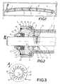
- the fabric expander shown schematically in Figure 1 comprises a fixed cylindrical shaft 1 curved longitudinally and mounted by supports 2 on a frame 3 of an enclosure 4 of a dyeing machine. Rollers 5 are rotatably mounted on the shaft 1, by means of intermediate bearing elements 6 and two rotary end pieces 7. These rollers form a tubular support with a polygonal longitudinal profile, which is coated with an envelope flexible tubular 8 whose ends are fixed to the end pieces 7 in a sealed manner.
- the fabric to be treated passes over the convex side of the expander, which it drives in rotation by friction on the envelope 8.
- FIG. 2 represents one of the end pieces 7 of the fabric expander according to the invention.
- This end piece comprises a metallic annular body 11 crossed by a straight end of the fixed shaft 1 and supported by the latter by a ball bearing 12.
- the bearing 12 is mounted on a bush 13 and wedged between a shoulder 14 of this sleeve and a retaining ring 15, the sleeve and the ring being locked by means of one or more screws 16 engaged in the shaft 1.
- the body 11 has a beveled end 17 on which is fitted the corresponding end of the first roller 5 surrounded by the tubular rubber casing 8.
- the end 18 of this casing is flared by application to a conical sealing surface 19 of the body 11, where it is pressed by means of an outer threaded sleeve 20 provided with an inner ring 21 having a conical surface 22 parallel to the surface 19.
- the tightening is effected by axial displacement of the sleeve 20 on a peripheral thread 23 of the body 11.
- stuffing box 25 This stuffing box comprises for example two disc-shaped packings 26, housed in a cylindrical bore of the body 11, and a tightening nut 27 engaged in a thread 28 of said bore.
- Blind holes 29 ( Figure 3) are provided on the outer front face 30 of the nut 27 to be able to rotate it by means of an appropriate key.
- this face 30 of the nut 27 carries a ring of axial fins 31 which are arranged at an angle with respect to the radial planes of the nut, preferably at an angle of approximately 35 °, to have an effect of centrifugal impeller when the nozzle 7 rotates around the shaft 1 in the direction of arrow A in the figure 3.
- Each fin 31 has a beveled front edge 32 near the shaft 1.
- the cable gland 25 When the expander does not rotate, the cable gland 25 provides sufficient sealing.
- one or more O-rings 33 can be provided on the inner cylindrical surface of the nut 27. The presence of these seals, as well as that of the fins 31, makes it possible to reduce the tightening force of the packings 26 of the cable gland and therefore extend their service life, without loss of tightness.
- An O-ring 11 ′ is also provided at the entry of the thread 23 to seal between the sleeve 20 and the body 11.
- FIG. 2 it can be seen that it is possible to easily change the linings 26 of the cable gland 25 if they are worn, by simply unscrewing the nut 27, without it being necessary to dismantle any other element of the tip 7. This saves not only the cost of the parts to be changed, but also the labor for maintenance work and the downtime of the expander. Tests have shown that the service life of such a tip is much greater than that of an O-ring tip according to the prior art. In particular, the bearing 12 is much better protected against corrosion, thanks to a more effective seal.
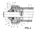
- FIG. 4 illustrates a variant in which the annular body 11 of the end piece 7 shown in FIG. 2 is made in two parts concentric, namely an inner annular element 11a and an outer annular element 11b which is screwed axially on an external thread 35 of the element 11a.
- the internal element 11a assures the fitting 7 on the shaft 1, by means of the bearing 12 and the sealing means, and it supports the first roller 5, as in the case of FIG. 2.
- the element exterior 11b ensures, in cooperation with the threaded sleeve 20, the fixing of the end 18 of the tubular rubber casing 8, pressed between the conical surfaces 19 of the body and 22 of the sleeve.
- This embodiment of the body in two elements has the advantage of facilitating the positioning of the sleeve 20 and the tightening of the end 18 of the tubular casing. It is further provided, through the elements 11a and 11b, a lubrication conduit 36 between the outer end of the body and the bearing 12, which makes it possible to lubricate the bearing without dismantling the end piece.
- a conventional lubricator (not shown) can be screwed into the external outlet 37 of the conduit 36.
- This lubrication conduit could also be provided through the body 11 of FIG. 2. The seal at the threads 23 and 35 is ensured by O-rings 11a 'and 11b'.
- FIGS. 5 and 6 illustrate a preferred embodiment of the rollers 5 and the intermediate elements 6 forming the rotary tubular support which supports the flexible tubular casing 8 of the fabric expander.
- the envelope and its support are rotated by the friction of the fabric passing under tension on the expander.
- the flexible envelope 8, which is free between these two ends held in the end pieces 7, then tends to slide in the circumferential direction on the rollers 5, so that it is subjected to torsional forces which may cause in the long run rubber cracks and breaks. Even when these breaks are minimal, this results in a leak which can lead to rapid deterioration of the metallic members of the expander.
- This drawback is avoided with the construction illustrated in FIGS. 5 and 6, which makes the rollers 5 integral in rotation with one another and thus reduces the relative sliding of the casing 8 on some of these rollers, in particular those which are distant from the end caps 7 where the casing is fixed.
- coupling means are provided between the rollers 5, so as to make them integral in rotation, while leaving sufficient axial play for the slight angular deviation existing between two adjacent rollers 5 because of the slight curvature. of the axis 40 of the shaft 1, as can be seen in FIG. 1.
- These means are produced by axial interlocking of the ends of the rollers 5 on the intermediate elements 6 which support them and each of which is mounted on the shaft at by means of a bearing 41.
- Each intermediate element 6 has a cylindrical outer surface 42 of the same diameter as the rollers 5, to support with them the flexible envelope 8.
- An orifice 43 may be formed in the surface 42 to give access to a bearing fixing screw 41.
- each roller 5 consisting simply of a metallic tubular element, is cut at each end to form two rectangular teeth 45 engaging in the corresponding recesses 44 of the intermediate element 6, where they are supported in the radial and circumferential direction, but benefit from the desired axial play.
- the present invention is not limited to the embodiment described above, but extends to any modification or variant obvious to a person skilled in the art.
- the method of fixing the flexible envelope 8 to the end piece 7 could be different and the sealing surface 19 between these two elements could have another configuration, for example with annular beads which "bite" in the envelope rubber.
- the invention also makes it possible to use a known method of fixing the flexible casing 8 where each end of the latter almost entirely surrounds the body of the endpiece and is folded inwards by a clamping ring, instead of being flared as described here.
Landscapes
- Engineering & Computer Science (AREA)
- Textile Engineering (AREA)
- Treatment Of Fiber Materials (AREA)
- Sealing Devices (AREA)
Applications Claiming Priority (2)
| Application Number | Priority Date | Filing Date | Title |
|---|---|---|---|
| FR9308447A FR2707306B1 (fr) | 1993-07-06 | 1993-07-06 | Elargisseur de tissu pour machine d'ennoblissement et de traitement. |
| FR9308447 | 1993-07-06 |
Publications (2)
| Publication Number | Publication Date |
|---|---|
| EP0638683A2 true EP0638683A2 (de) | 1995-02-15 |
| EP0638683A3 EP0638683A3 (de) | 1996-06-19 |
Family
ID=9449092
Family Applications (1)
| Application Number | Title | Priority Date | Filing Date |
|---|---|---|---|
| EP94440044A Withdrawn EP0638683A3 (de) | 1993-07-06 | 1994-07-04 | Breithalter für Nachbehandlungvorrichtungen von Geweben. |
Country Status (2)
| Country | Link |
|---|---|
| EP (1) | EP0638683A3 (de) |
| FR (1) | FR2707306B1 (de) |
Cited By (3)
| Publication number | Priority date | Publication date | Assignee | Title |
|---|---|---|---|---|
| WO2001049916A1 (en) * | 1999-12-29 | 2001-07-12 | Owens Corning | Applicator roll |
| CN106811887A (zh) * | 2017-04-05 | 2017-06-09 | 刘运华 | 一种服装生产用无纺布染色装置 |
| CN119873133A (zh) * | 2025-01-22 | 2025-04-25 | 江苏华越毛纺有限公司 | 纺织品存储组件 |
Family Cites Families (4)
| Publication number | Priority date | Publication date | Assignee | Title |
|---|---|---|---|---|
| US1953177A (en) * | 1933-10-18 | 1934-04-03 | Isherwood Arthur | Cloth spreader or expander |
| US3357073A (en) * | 1965-05-10 | 1967-12-12 | American Cloth Strait Company | Curved roll |
| BE758850A (fr) * | 1969-11-12 | 1971-04-16 | H Wittler & Co Fa | Cylindre calendreur pour nappes de textile, papier ou matieres plastiques souples |
| US3666049A (en) * | 1970-10-12 | 1972-05-30 | Kern Roll And Rubber Co | Expander roll assembly with oil-mist lubrication |
-
1993
- 1993-07-06 FR FR9308447A patent/FR2707306B1/fr not_active Expired - Fee Related
-
1994
- 1994-07-04 EP EP94440044A patent/EP0638683A3/de not_active Withdrawn
Cited By (4)
| Publication number | Priority date | Publication date | Assignee | Title |
|---|---|---|---|---|
| WO2001049916A1 (en) * | 1999-12-29 | 2001-07-12 | Owens Corning | Applicator roll |
| US6358317B1 (en) | 1999-12-29 | 2002-03-19 | Owens Corning Fiberglas Technology, Inc. | Radial contact applicator roll |
| CN106811887A (zh) * | 2017-04-05 | 2017-06-09 | 刘运华 | 一种服装生产用无纺布染色装置 |
| CN119873133A (zh) * | 2025-01-22 | 2025-04-25 | 江苏华越毛纺有限公司 | 纺织品存储组件 |
Also Published As
| Publication number | Publication date |
|---|---|
| EP0638683A3 (de) | 1996-06-19 |
| FR2707306B1 (fr) | 1995-11-10 |
| FR2707306A1 (fr) | 1995-01-13 |
Similar Documents
| Publication | Publication Date | Title |
|---|---|---|
| FR2576383A1 (fr) | Joint d'etancheite a monter sur le troncon conique d'un tourillon de cylindre de laminoir | |
| FR3032765A1 (fr) | Dispositif d'etancheite pour paliers a roulement, en particulier pour un palier de moyeu de vehicules, et roulement de moyeu associe. | |
| FR2642815A1 (fr) | Procede de fixation d'un tuyau souple a un raccord filete et raccordement de tuyau souple obtenu grace a ce procede | |
| FR2568970A1 (fr) | Dispositif d'etancheite aux fluides, notamment pour arbres | |
| FR2657655A1 (fr) | Pompe a vide avec des cylindres filetes helicouidalement. | |
| CA2646976A1 (fr) | Etancheite de fixation de support de palier dans une turbomachine | |
| FR2704617A1 (fr) | Garniture d'étanchéité pour arbre tournant. | |
| FR2535815A1 (fr) | Joint d'etancheite exempt de contact | |
| CH341038A (fr) | Dispositif d'étanchéité | |
| EP0638683A2 (de) | Breithalter für Nachbehandlungvorrichtungen von Geweben | |
| FR2540213A1 (fr) | Dispositif d'etanchement d'un arbre rotatif, ensemble a arbre rotatif equipe de ce dispositif et turbocompresseur dont le rotor est muni dudit dispositif | |
| FR2464402A1 (fr) | Palier a rouleaux du type ayant une bague d'etancheite capable de faire circuler de force le lubrifiant | |
| FR2967748A1 (fr) | Systeme d'etancheite a joint annulaire a brosse | |
| FR2604226A1 (fr) | Dispositif pour rendre etanches des paliers d'arbre ou des carters de palier d'arbre. | |
| EP3111116B1 (de) | Reduzierung der leckageflussrate einer bürstendichtung durch flexible geometrische blockierung | |
| FR2650130A1 (fr) | Joint d'etancheite, dispositif d'etancheite et machine dynamoelectrique ainsi equipes, et ensemble de composants s'y rapportant | |
| FR2482878A1 (de) | ||
| EP1591714A1 (de) | Vorrichtung zum Schmieren eines Teils in einem Zusammenbau | |
| FR2828921A1 (fr) | Dispositif d'etancheite entre deux elements de machine, notamment entre un carter et un arbre | |
| FR2473671A1 (fr) | Vanne a bille demontable | |
| FR2525320A1 (fr) | Joint pour assurer l'etancheite avec la surface peripherique d'un objet cylindrique tel qu'un pointeau de valve | |
| FR2711205A1 (fr) | Dispositif d'étanchéité pour arbre tournant. | |
| FR2458489A1 (fr) | Dispositif de graissage pour les paliers de montage du tambour a chaines d'un convoyeur a raclettes a chaines | |
| FR2693774A1 (fr) | Dispositif de fixation étanche à vis. | |
| CH343728A (fr) | Dispositif d'étanchéité aux fluides entre un arbre rotatif et un logement entourant cet arbre |
Legal Events
| Date | Code | Title | Description |
|---|---|---|---|
| PUAI | Public reference made under article 153(3) epc to a published international application that has entered the european phase |
Free format text: ORIGINAL CODE: 0009012 |
|
| AK | Designated contracting states |
Kind code of ref document: A2 Designated state(s): AT BE CH DE DK ES FR GB IT LI NL SE |
|
| 17P | Request for examination filed |
Effective date: 19950807 |
|
| PUAL | Search report despatched |
Free format text: ORIGINAL CODE: 0009013 |
|
| AK | Designated contracting states |
Kind code of ref document: A3 Designated state(s): AT BE CH DE DK ES FR GB IT LI NL SE |
|
| RBV | Designated contracting states (corrected) |
Designated state(s): AT BE CH DE DK ES FR GB IT LI NL SE |
|
| GRAG | Despatch of communication of intention to grant |
Free format text: ORIGINAL CODE: EPIDOS AGRA |
|
| 17Q | First examination report despatched |
Effective date: 19971124 |
|
| STAA | Information on the status of an ep patent application or granted ep patent |
Free format text: STATUS: THE APPLICATION IS DEEMED TO BE WITHDRAWN |
|
| 18D | Application deemed to be withdrawn |
Effective date: 19980202 |