EP0638691A1 - Cisaille à grand rendement - Google Patents
Cisaille à grand rendement Download PDFInfo
- Publication number
- EP0638691A1 EP0638691A1 EP93112962A EP93112962A EP0638691A1 EP 0638691 A1 EP0638691 A1 EP 0638691A1 EP 93112962 A EP93112962 A EP 93112962A EP 93112962 A EP93112962 A EP 93112962A EP 0638691 A1 EP0638691 A1 EP 0638691A1
- Authority
- EP
- European Patent Office
- Prior art keywords
- lower jaw
- jaw
- shear
- upper jaw
- cutter
- Prior art date
- Legal status (The legal status is an assumption and is not a legal conclusion. Google has not performed a legal analysis and makes no representation as to the accuracy of the status listed.)
- Granted
Links
- 238000010276 construction Methods 0.000 claims abstract description 6
- 238000006073 displacement reaction Methods 0.000 abstract description 6
- 238000010008 shearing Methods 0.000 abstract description 5
- 239000000126 substance Substances 0.000 description 2
- 229910000851 Alloy steel Inorganic materials 0.000 description 1
- 229910001209 Low-carbon steel Inorganic materials 0.000 description 1
- 229910000831 Steel Inorganic materials 0.000 description 1
- 230000000295 complement effect Effects 0.000 description 1
- 230000000694 effects Effects 0.000 description 1
- 239000011150 reinforced concrete Substances 0.000 description 1
- 239000010959 steel Substances 0.000 description 1
Images


Classifications
-
- E—FIXED CONSTRUCTIONS
- E02—HYDRAULIC ENGINEERING; FOUNDATIONS; SOIL SHIFTING
- E02F—DREDGING; SOIL-SHIFTING
- E02F3/00—Dredgers; Soil-shifting machines
- E02F3/04—Dredgers; Soil-shifting machines mechanically-driven
- E02F3/28—Dredgers; Soil-shifting machines mechanically-driven with digging tools mounted on a dipper- or bucket-arm, i.e. there is either one arm or a pair of arms, e.g. dippers, buckets
- E02F3/36—Component parts
- E02F3/3604—Devices to connect tools to arms, booms or the like
- E02F3/3677—Devices to connect tools to arms, booms or the like allowing movement, e.g. rotation or translation, of the tool around or along another axis as the movement implied by the boom or arms, e.g. for tilting buckets
- E02F3/3681—Rotators
-
- B—PERFORMING OPERATIONS; TRANSPORTING
- B23—MACHINE TOOLS; METAL-WORKING NOT OTHERWISE PROVIDED FOR
- B23D—PLANING; SLOTTING; SHEARING; BROACHING; SAWING; FILING; SCRAPING; LIKE OPERATIONS FOR WORKING METAL BY REMOVING MATERIAL, NOT OTHERWISE PROVIDED FOR
- B23D17/00—Shearing machines or shearing devices cutting by blades pivoted on a single axis
-
- E—FIXED CONSTRUCTIONS
- E02—HYDRAULIC ENGINEERING; FOUNDATIONS; SOIL SHIFTING
- E02F—DREDGING; SOIL-SHIFTING
- E02F3/00—Dredgers; Soil-shifting machines
- E02F3/04—Dredgers; Soil-shifting machines mechanically-driven
- E02F3/96—Dredgers; Soil-shifting machines mechanically-driven with arrangements for alternate or simultaneous use of different digging elements
- E02F3/965—Dredgers; Soil-shifting machines mechanically-driven with arrangements for alternate or simultaneous use of different digging elements of metal-cutting or concrete-crushing implements
Definitions
- the present invention relates to a heavy duty shear for use in the demolition of buildings and other structures.
- each of the jaws is recessed away from the other so as to prevent a forward slide of the gripped load.
- the upper jaw 4 is constituted as a single-row element and the lower jaw 1 as an element formed in a couple of rows in such a manner that the forward part of the upper jaw 4 may swing down into the space between the two rows of lower jaw 1.
- the members of lower jaw 1 corresponding to said two rows are provided with a front cross member 6 interconnecting the forward ends of said lower jaw members to preclude a lateral expansion of the space between the rows.
- the lateral sides of upper and lower jaws 1,4 which are to face each other are provided with a plurality of cutters 7, 7a, 8, 9, respectively. Further disposed on the lateral sides of upper jaw 4 and lower jaw 1 which are opposite to the sides provided with said cutters 7, 7a, 8, 9 are wear plates 10 and 11, respectively, for precluding a lateral displacement of the upper jaw 4 in shearing.
- Japanese Tokkyo Kokai Koho S-56-49273 discloses a heavy duty shear comprising a cylinder housing dismountably secured to a power shovel arm through a swivel device and a pair of cutter bodies rotatably supported about a pivotal shaft on said cylinder housing, with each of said cutter bodies being formed in a single row.
- the above shear comprising a couple of cutter bodies (equivalent to jaws) each constituted in a single row is lightweight and compact but the forward parts of the cutter bodies tend to be displaced laterally in shearing a load.
- the present invention provides a heavy duty shear which can be rotatably mounted, as an attachment, at the free end of a construction machine arm, comprising a stationary lower jaw having a cutter means and a movable upper jaw having a cutter means, said lower jaw being a single-row member extending integrally from a cylinder housing which is disposed in a generally vertical position and housing a hydraulic cylinder, said upper jaw being a single-row member with its intermediate portion supported by a pivotal shaft mounted on said cylinder housing and its rear end connected to said hydraulic cylinder, said lower jaw having a front end element disposed in parallel with said pivotal shaft and further having an engaging member extending some distance rearwardly thereof in parallel with the cutter means of said lower jaw to present a configuration generally conforming to the numeral 7 in such a manner that the forward part of said upper jaw is free to swing down into a space between said cutter and engaging member, with the inner lateral side of said lower jaw being defined by a smooth curved plane conjoining its inner
- the illustrated embodiment is particularly suited for use as a heavy duty shear mounted, as an attachment, on the free end of the arm of a construction machine, typically a power shovel. It is also suited as a specialty demolishing equipment for chemical plant pipelines, motor vehicles, railroad coaches and so on.
- the shear of the invention preferably weighs about 3800 kg and has a front opening about 600 mm wide and a cutter length of about 800 mm.
- the shear according to this embodiment has a built-in hydraulic cylinder disposed in a generally vertical position for opening and closing the jaws. Moreover, its upper and lower jaws are formed each in a single row to realize a reduced overall weight and insure a smooth rotation with respect to the power shovel arm.
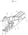
- a lower jaw 1 extends integrally from a cylinder housing 12, while an upper jaw 4 is rotatably supported, in an approximate center, by a pivotal shaft 3 mounted on said cylinder housing 12 in such a manner that it is free to swing in vertical directions to open and close with respect to the lower jaw 1.
- the lower jaw 1 has an intermediate recess 13 along its length extending from said pivotal shaft 3 toward its forward end and the upper jaw 4 also has an intermediate recess 14 corresponding to said recess 13 of lower jaw 1.
- these recesses 13, 14 of the upper and lower jaws 4, 1 constitute, therebetween, a free space which serves to prevent a forward slide of the gripped load.
- the side of the lower jaw 1 which confronts the upper jaw 4 has cutters 8, 9 removably secured thereto, along said recess 13, by bolts 15.
- the cutter 9 of lower jaw 1 and the cutter 7a of upper jaw 4 form a shear angle between them.
- a mild steel load is shorn at a shear angle of less than 55°, the load does not slide forward.
- the above-mentioned cylinder housing 12 is formed with a cylinder boss 12a at its bottom and the end of a rod 16 of a hydraulic cylinder 5a is rotatably supported by the boss 12a.
- This hydraulic cylinder 5a is disposed in a generally vertical position within the cylinder housing 12 and connected to the rear portion of said upper jaw 4. Therefore, when the hydraulic cylinder 5a is actuated, the upper jaw 4 is rotated to open or close with respect to the lower jaw 1.
- This arrangement also is conducive to the compact design of the whole shear.
- This swing end plate 17 is rigidly secured to said rear face of cylinder housing 12, while the mounting end plate 18 is rigidly secured to a bracket 19.
- This bracket 19 is provided with an arm pin 20 for connection to the arm of a power shovel (not shown) and a cylinder pin 21 for connection to a booming hydraulic cylinder (not shown) disposed in parallel with the power shovel arm.
- the above-mentioned swing end plate 17 carries a bearing 28 having an internal gear and said mounting end plate 18 has, as built therein, a hydraulic motor equipped with a pinion (not shown) or a swing brake device having a pinion and a swivel joint for free rotation.
- the swing end plate 20 is swung to allow the whole shear to rotate through 360° with respect to the power shovel arm.
- the following lateral stop means is provided to preclude a lateral displacement of the upper jaw 4.
- the forward end of the lower jaw 1 has a front element 6 disposed in parallel with the pivotal shaft 3 and extending beyound the lateral width of the forward end of the upper jaw 4 and this front element 6 is formed with a short rearwardly extending engaging member 23 in parallel with the cutter 8 of the lower jaw 1.
- the lower jaw 1 is generally configured in the manner of the numeral 7 in plan view so that the upper jaw 4 is prevented by the engaging member 23 against lateral displacement.
- the lower jaw 1 is configured, in plan view, in such a manner that the side of its base and the forward inner side thereof are conjoined by a smooth gently curved surface 24. Moreover, the forward side of said front element 6 is provided with a projection (not shown) for free rotation.
- the forward end of said front element 6 is chamfered at 25, 25 for reduced weight and the inner surface 22 of said front element 6 is inclined along a plane complementary to the forward end of the upper jaw 4.
- a bolt hole for said bolt 15 is shown at 26 and a mounting recess for said cutters 8, 9 is shown at 27.
- the stationary lower jaw is formed with a front end element having an engaging member extending some distance rearwardly in parallel with the cutter of the lower jaw, with the result that when the forward part of the upper jaw swings down into the space between said cutter and engaging member of the lower jaw to shear the load, displacement of the upper jaw in shearing is prevented by said engaging member.
- the curved surface of the lower jaw which is formed in a single row, provides for a large space, the load can be easily gripped in the space. Moreover, the whole shear can be reduced in weight so that it can freely rotate at the tip of a construction machine arm.
Landscapes
- Engineering & Computer Science (AREA)
- Mechanical Engineering (AREA)
- Structural Engineering (AREA)
- Mining & Mineral Resources (AREA)
- Civil Engineering (AREA)
- General Engineering & Computer Science (AREA)
- Working Measures On Existing Buildindgs (AREA)
- Shovels (AREA)
Priority Applications (3)
| Application Number | Priority Date | Filing Date | Title |
|---|---|---|---|
| US08/103,364 US5375329A (en) | 1993-08-09 | 1993-08-09 | Heavy duty shear |
| EP93112962A EP0638691B1 (fr) | 1993-08-09 | 1993-08-12 | Cisaille à grand rendement |
| DE1993619339 DE69319339T2 (de) | 1993-08-12 | 1993-08-12 | Hochleistungsschere |
Applications Claiming Priority (2)
| Application Number | Priority Date | Filing Date | Title |
|---|---|---|---|
| US08/103,364 US5375329A (en) | 1993-08-09 | 1993-08-09 | Heavy duty shear |
| EP93112962A EP0638691B1 (fr) | 1993-08-09 | 1993-08-12 | Cisaille à grand rendement |
Publications (2)
| Publication Number | Publication Date |
|---|---|
| EP0638691A1 true EP0638691A1 (fr) | 1995-02-15 |
| EP0638691B1 EP0638691B1 (fr) | 1998-06-24 |
Family
ID=26133364
Family Applications (1)
| Application Number | Title | Priority Date | Filing Date |
|---|---|---|---|
| EP93112962A Expired - Lifetime EP0638691B1 (fr) | 1993-08-09 | 1993-08-12 | Cisaille à grand rendement |
Country Status (2)
| Country | Link |
|---|---|
| US (1) | US5375329A (fr) |
| EP (1) | EP0638691B1 (fr) |
Families Citing this family (7)
| Publication number | Priority date | Publication date | Assignee | Title |
|---|---|---|---|---|
| JP3058247B2 (ja) * | 1995-08-24 | 2000-07-04 | 大淀ヂ−ゼル株式会社 | 鎌型剪断機 |
| AT403491B (de) * | 1996-02-15 | 1998-02-25 | Wimmer Alois Ing | Betonbrechzange mit schneidschere |
| EP1361322B1 (fr) * | 2001-02-07 | 2013-04-03 | Okada Aiyon Corporation | Dispositif de pulverisation |
| CA2353239A1 (fr) * | 2001-07-18 | 2003-01-18 | Rotobec Inc. | Rotor a moteur monte sur bras |
| DK174322B1 (da) * | 2001-09-27 | 2002-12-09 | Keld Noergaard | Kilepar til opklodsning og fiksering af vinduer og døre |
| US8146256B2 (en) | 2003-10-31 | 2012-04-03 | Stanley Black & Decker, Inc. | Metal demolition shears with indexable, integrated wear plate/piercing tip |
| US20070145171A1 (en) * | 2005-12-23 | 2007-06-28 | The Stanley Works | Rebar cutting shears |
Citations (3)
| Publication number | Priority date | Publication date | Assignee | Title |
|---|---|---|---|---|
| US4403431A (en) * | 1982-07-19 | 1983-09-13 | Michael Ramun | Self-contained material handling and shearing attachment for a backhoe |
| US4519135A (en) * | 1982-09-13 | 1985-05-28 | Labounty Roy E | Metal demolition shear |
| US5187868A (en) * | 1992-06-16 | 1993-02-23 | Hall Charlie R | Metal demolition shear |
Family Cites Families (4)
| Publication number | Priority date | Publication date | Assignee | Title |
|---|---|---|---|---|
| JPS5826470B2 (ja) * | 1979-09-05 | 1983-06-02 | 鹿島建設株式会社 | 避難通路を有する建築物 |
| US4847921A (en) * | 1986-04-28 | 1989-07-18 | Eye Mask, Inc. | Protective headgear |
| JPH079970Y2 (ja) * | 1991-05-20 | 1995-03-08 | 大淀小松株式会社 | 鉄骨切断機 |
| US5230151A (en) * | 1992-02-26 | 1993-07-27 | N.P.K. Construction Equipment, Inc. | Heavy duty shear head and mounting support |
-
1993
- 1993-08-09 US US08/103,364 patent/US5375329A/en not_active Expired - Fee Related
- 1993-08-12 EP EP93112962A patent/EP0638691B1/fr not_active Expired - Lifetime
Patent Citations (3)
| Publication number | Priority date | Publication date | Assignee | Title |
|---|---|---|---|---|
| US4403431A (en) * | 1982-07-19 | 1983-09-13 | Michael Ramun | Self-contained material handling and shearing attachment for a backhoe |
| US4519135A (en) * | 1982-09-13 | 1985-05-28 | Labounty Roy E | Metal demolition shear |
| US5187868A (en) * | 1992-06-16 | 1993-02-23 | Hall Charlie R | Metal demolition shear |
Also Published As
| Publication number | Publication date |
|---|---|
| EP0638691B1 (fr) | 1998-06-24 |
| US5375329A (en) | 1994-12-27 |
Similar Documents
| Publication | Publication Date | Title |
|---|---|---|
| US5146683A (en) | Reinforcement cutter | |
| CA1204657A (fr) | Dispositif aroseur | |
| US5339525A (en) | Reinforcing steel shear | |
| US4686767A (en) | Metal cutting shear for a backhoe | |
| US4480955A (en) | Coupling for earth moving tools etc. | |
| EP1163079B1 (fr) | Appareil de demolition a usage industriel dote d'une pointe de broyage et de cisaillement remplacable | |
| US5108252A (en) | Quick-disconnect coupling for a machine having a boom and a stick | |
| US5384962A (en) | Apparatus for shearing a material mass | |
| EP1218600B1 (fr) | Appareil de coupe ou de broyage | |
| US20140217219A1 (en) | Multiple Tool Attachment System | |
| US6718663B1 (en) | Assembly for coupling implements to excavating machines | |
| US6158950A (en) | Excavator coupling | |
| JPH0321283B2 (fr) | ||
| US8491251B2 (en) | Gripping device of working machine and working machine with the same | |
| US4196862A (en) | Apparatus for crushing building materials | |
| JPH0617438A (ja) | 半自動カップリング装置 | |
| US5375329A (en) | Heavy duty shear | |
| JPS6055170A (ja) | 鉄骨切断装置 | |
| GB2122125A (en) | Shear apparatus | |
| GB2157215A (en) | Shear apparatus | |
| CN117967341A (zh) | 一种三臂拱锚台车 | |
| JPH073121B2 (ja) | 鋼材剪断機 | |
| JPH05169309A (ja) | 鋼剪断機 | |
| EP0500843A1 (fr) | Dispositif de redressement pour carrosserie de voiture. | |
| JPH0732765Y2 (ja) | 鋼等剪断機 |
Legal Events
| Date | Code | Title | Description |
|---|---|---|---|
| PUAI | Public reference made under article 153(3) epc to a published international application that has entered the european phase |
Free format text: ORIGINAL CODE: 0009012 |
|
| AK | Designated contracting states |
Kind code of ref document: A1 Designated state(s): DE FR GB IT NL |
|
| 17P | Request for examination filed |
Effective date: 19950309 |
|
| 17Q | First examination report despatched |
Effective date: 19960404 |
|
| GRAG | Despatch of communication of intention to grant |
Free format text: ORIGINAL CODE: EPIDOS AGRA |
|
| GRAG | Despatch of communication of intention to grant |
Free format text: ORIGINAL CODE: EPIDOS AGRA |
|
| GRAG | Despatch of communication of intention to grant |
Free format text: ORIGINAL CODE: EPIDOS AGRA |
|
| GRAH | Despatch of communication of intention to grant a patent |
Free format text: ORIGINAL CODE: EPIDOS IGRA |
|
| GRAH | Despatch of communication of intention to grant a patent |
Free format text: ORIGINAL CODE: EPIDOS IGRA |
|
| GRAA | (expected) grant |
Free format text: ORIGINAL CODE: 0009210 |
|
| AK | Designated contracting states |
Kind code of ref document: B1 Designated state(s): DE FR GB IT NL |
|
| ITF | It: translation for a ep patent filed | ||
| REF | Corresponds to: |
Ref document number: 69319339 Country of ref document: DE Date of ref document: 19980730 |
|
| ET | Fr: translation filed | ||
| PLBE | No opposition filed within time limit |
Free format text: ORIGINAL CODE: 0009261 |
|
| STAA | Information on the status of an ep patent application or granted ep patent |
Free format text: STATUS: NO OPPOSITION FILED WITHIN TIME LIMIT |
|
| 26N | No opposition filed | ||
| PGFP | Annual fee paid to national office [announced via postgrant information from national office to epo] |
Ref country code: GB Payment date: 20010809 Year of fee payment: 9 |
|
| PGFP | Annual fee paid to national office [announced via postgrant information from national office to epo] |
Ref country code: NL Payment date: 20010831 Year of fee payment: 9 |
|
| PGFP | Annual fee paid to national office [announced via postgrant information from national office to epo] |
Ref country code: DE Payment date: 20011029 Year of fee payment: 9 |
|
| REG | Reference to a national code |
Ref country code: GB Ref legal event code: IF02 |
|
| PGFP | Annual fee paid to national office [announced via postgrant information from national office to epo] |
Ref country code: FR Payment date: 20020626 Year of fee payment: 10 |
|
| PG25 | Lapsed in a contracting state [announced via postgrant information from national office to epo] |
Ref country code: GB Free format text: LAPSE BECAUSE OF NON-PAYMENT OF DUE FEES Effective date: 20020812 |
|
| PG25 | Lapsed in a contracting state [announced via postgrant information from national office to epo] |
Ref country code: NL Free format text: LAPSE BECAUSE OF NON-PAYMENT OF DUE FEES Effective date: 20030301 Ref country code: DE Free format text: LAPSE BECAUSE OF NON-PAYMENT OF DUE FEES Effective date: 20030301 |
|
| GBPC | Gb: european patent ceased through non-payment of renewal fee |
Effective date: 20020812 |
|
| NLV4 | Nl: lapsed or anulled due to non-payment of the annual fee |
Effective date: 20030301 |
|
| PG25 | Lapsed in a contracting state [announced via postgrant information from national office to epo] |
Ref country code: FR Free format text: LAPSE BECAUSE OF NON-PAYMENT OF DUE FEES Effective date: 20040430 |
|
| REG | Reference to a national code |
Ref country code: FR Ref legal event code: ST |
|
| PG25 | Lapsed in a contracting state [announced via postgrant information from national office to epo] |
Ref country code: IT Free format text: LAPSE BECAUSE OF NON-PAYMENT OF DUE FEES;WARNING: LAPSES OF ITALIAN PATENTS WITH EFFECTIVE DATE BEFORE 2007 MAY HAVE OCCURRED AT ANY TIME BEFORE 2007. THE CORRECT EFFECTIVE DATE MAY BE DIFFERENT FROM THE ONE RECORDED. Effective date: 20050812 |