EP0638875B1 - Appareil et méthode pour génération d'animation en 3 dimensions - Google Patents
Appareil et méthode pour génération d'animation en 3 dimensions Download PDFInfo
- Publication number
- EP0638875B1 EP0638875B1 EP94112059A EP94112059A EP0638875B1 EP 0638875 B1 EP0638875 B1 EP 0638875B1 EP 94112059 A EP94112059 A EP 94112059A EP 94112059 A EP94112059 A EP 94112059A EP 0638875 B1 EP0638875 B1 EP 0638875B1
- Authority
- EP
- European Patent Office
- Prior art keywords
- image data
- view point
- dimensional
- observing
- vertexes
- Prior art date
- Legal status (The legal status is an assumption and is not a legal conclusion. Google has not performed a legal analysis and makes no representation as to the accuracy of the status listed.)
- Expired - Lifetime
Links
Images



Classifications
-
- G—PHYSICS
- G06—COMPUTING OR CALCULATING; COUNTING
- G06T—IMAGE DATA PROCESSING OR GENERATION, IN GENERAL
- G06T13/00—Animation
- G06T13/20—Three-dimensional [3D] animation
Definitions
- the present invention relates to a 3-dimensional animation generating apparatus and a method using such apparatus according to the technical field of claim 1 and claim 10 of the present invention.
- a computer controlled digital imaging system which operates to compose and construct a sequential stream of scenes for a display from a library of images of objects.
- the system is suitable for two dimensional applications such as a helicopter simulator where a perspective mapping process is provided for mapping images of objects which appear in the field of windshield-view from the corresponding images in the library to the face of the monitor screen.
- animation is often generated by a method called key-frame interpolation.
- key frames some reference frames (hereinafter referred to as key frames) along the time axis are selected, and frame images between respective key frames are interpolated by utilizing the similarities between the frame images in the key frames. More specifically, the interpolation is performed by detecting or estimating a motion vector originating from the key frame for each of pixels which constitute an object existing in a frame.
- the quality of generated images is necessarily deteriorated.
- the thus generated image is said to be "3-dimensional", it is actually a pseudo 3-dimensional image which is projected on a 2-dimensional plane. It should precisely be called a 2.5-dimensional image.
- the image data stored in the image data storing means are background image data and part image data of the respective parts with respect to a plurality of projected images which are respectively obtained by projecting the object onto a plurality of project surfaces from a plurality of reference view points
- the image data storing means stores the image data in a hierarchical structure, the image data being stored in association with 3-dimensional coordinates in a world coordinate system of respective vertexes of a figure existing in the respective projected images and being attached with an identification code indicative of additional information on the image data.
- the image data selecting means judges a positional relationship between the observing view point and the image data through a positional relationship between the 3-dimensional coordinates of the vertexes and 3-dimensional coordinates of the observing view point, and searches the image data by utilizing the identification code.
- the view point coordinate transforming means determines one vertex of the part in the image data to be processed as a reference vertex, and the coordinate transformation is performed with respect to vectors connecting the reference vertex and other vertexes of the part.
- the view point coordinate transforming means removes a hidden surface formed by overlapping a plurality of transformed part image data for a plain produced by the vertexes of the part image data as a minimum unit, and processes interpolation for pixels excluding the vertexes in the part image data based on the original image data before the coordinate transformation.
- the apparatus further includes a motion addressing means for providing motion data on a motion of the object, wherein the image data selecting means searches a specific part image data among the part image data stored in the image data storing means, the specific part image data corresponding to a specific part to be moved in relation to the motion of the object, and the view point coordinate transforming means transforms the searched part image data into a transformed part image data in a moved condition, the transformed part image data being drawn on the drawing area.
- the apparatus further includes: a shadow area detecting means for detecting an area to be a shadow area by using the 3-dimensional coordinates of the vertexes of the parts in the stored part image data and the 3-dimensional coordinates of a light source; and a shadow area supervising means for supervising image data of the shadow area, wherein a movement of the shadow area corresponding a movement of the observing view point is calculated by view point coordinate transformation of the part image data which provides the shadow area, the shadow area being drawn in the drawing area by decreasing luminance values of pixels included in the shadow area.
- the image data storing means stores the image data in a plurality of hierarchical structures arranged sequentially along a time axis.
- the method for generating a 3-dimensional animation in which a scene including an object having a 3-dimensional shape is drawn includes the steps of: representing the object in approximation with one or more parts and storing image data relating to the respective parts, the respective parts being a group of polygons, the polygons representing a surface of the object; supervising and searching the image data for each part as a minimum unit; providing information on an observing view point from which the object is observed; selecting a visible image data which is visible from the observing view point among the stored image data by using the information on the observing view point provided; performing a coordinate transformation of the image data with respect to coordinates of the observing view point by using the information on the observing view point; and drawing the transformed image data on a drawing area.
- the polygons included in the respective parts are adjacent to each other and respective directions of respective normal vectors of the respective polygons fall within a predetermined range.
- the image data stored are background image data and part image data of the respective parts with respect to a plurality of projected images which are respectively obtained by projecting the object onto a plurality of project surfaces from a plurality of reference view points, and the image data is stored in a hierarchical structure and in association with 3-dimensional coordinates in a world coordinate system of respective vertexes of a figure existing in the respective projected images and being attached with an identification code indicative of additional information on the image data.
- a positional relationship between the observing view point and the image data is judged through a positional relationship between the 3-dimensional coordinates of the vertexes and 3-dimensional coordinates of the observing view point, and the image data is searched by utilizing the identification code.
- the step of performing the coordinate transformation further includes the step of determining one vertex of the part in the image data to be processed as a reference vertex, wherein the coordinate transformation is performed with respect to vectors connecting the reference vertex and other vertexes of the part.
- the method further includes the steps of: removing a hidden surface formed by overlapping a plurality of transformed part image data for a plain produced by the vertexes of the part image data as a minimum unit; and processing interpolation for pixels excluding the vertexes in the part image data based on the original image data before the coordinate transformation.
- the method further includes the steps of: providing a motion data on a motion of the object; searching a specific part image data among the stored part image data, the specific part image data corresponding to a specific part to be moved in relation to the motion of the object; transforming the searched part image data into a transformed part image data in a moved condition; and drawing the transformed part image data being drawn on the drawing area.
- the method further includes the steps of: detecting an area to be a shadow area by using the 3-dimensional coordinates of the vertexes of the parts in the stored part image data and the 3-dimensional coordinates of a light source; supervising image data of the shadow area; calculating a movement of the shadow area corresponding a movement of the observing view point by view point coordinate transformation of the part image data which provides the shadow area; and drawing the shadow area in the drawing area by decreasing luminance values of pixels included in the shadow area.
- the image data is stored in a plurality of hierarchical structures arranged in a sequential manner along a time axis.
- the invention described herein makes possible the advantage of providing an apparatus and a method for generating 3-dimensional animation by which 3-dimensional animation with a high image quality is easily generated in real time.
- Figure 1 is a block diagram for illustrating a construction of a 3-dimensional animation generating apparatus in one embodiment of the invention.
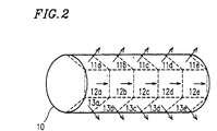
- Figure 2 is a schematic diagram for illustrating a method for representing a shape of an object in approximation.
- Figures 3A to 3C are schematic diagrams showing the relationships between an object and stored image data.
- Figure 4 is a diagram for illustrating a hierarchy used for storing and supervising the image data.
- Figure 5 is a schematic diagram for illustrating a method for detecting a visible area.
- Figures 6A and 6B are schematic diagrams for illustrating view point coordinate transformation.
- Figure 7 is a schematic diagram for illustrating hidden surface removal.
- Figures 8A and 8B are schematic diagrams for illustrating a shadow area and view point coordinate transformation for the shadow area.
- Figure 9 is a schematic diagram for illustrating another embodiment of the invention which utilizes a sphere for obtaining part image data.
- Figure 10 is a diagram for illustrating another hierarchy used for storing and supervising the part image data.
- Figure 1 schematically shows the construction of the 3-dimensional animation generating apparatus in this embodiment.
- the apparatus includes an image data storing section 1 , a view point information input section 2 , an image supervising section 3 , an image data selecting section 4 , a view point coordinate transforming section 5 , an output image drawing section 6 , a motion addressing section 7 , a shadow area detecting section 8 , and a shadow area supervising section 9 .
- Functions of the respective sections 1 to 9 and the operation of the 3-dimensional animation generating apparatus as a whole will be described below.
- the image data storing section 1 stores image data of an object existing in a scene to be generated and image data of background (hereinafter referred to as background image data).
- background image data image data of background
- the image data of an object is obtained in the following manner.
- Each object is represented using "parts", and each part is observed from a plurality of reference view points.
- the observed resultant image is regarded as image data for each part of the object (hereinafter referred to as part image data).
- CG for example as schematically shown in Figure 2
- the shape of an object 10 existing in the scene is generally represented in approximation by using a plurality of polygons 11a - 11e, 12a - 12e, and 13a - 13e .
- the directions of the respective polygons 11a - 11e, 12a - 12e , and 13a - 13e are indicated by normal vectors shown as arrows in Figure 2 .
- the ones which are adjacent to each other and of which the directions of normal vectors fall within a predetermined range are regarded as a group and treated as one part.
- the polygons 11a - 11e constitute a first part, in which the respective polygons 11a - 11e included therein have the normal vector in the direction perpendicular to the drawing surface.
- the polygons 12a - 12e constitute a second part
- the polygons 13a - 13e constitute a third part.
- the 3-dimensional coordinates of an object in the scene are known parameters.
- the image data storing section 1 actually stores vertex coordinates (3 dimensions) in the world coordinate system of the vertexes of each of the parts which are viewed from a plurality of arbitrarily selected reference view points.
- the images obtained by viewing the object from the plurality of reference view points are images of respective parts when the scene is parallel-projected onto an imaginary surface.
- the positions of the plurality of reference view points are determined so that parts in the scene can be viewed, based on the positions of the view points actually selected by a user for observing the generated scene (hereinafter referred to as observing view points).
- the number, the positions, and the directions of the reference view points can be desirably selected.
- FIG. 3A For example, consider a scene Scene1 in which three objects (rectangular parallelepipeds) O 1 , O 2 , and O 3 exist as shown in Figure 3A.
- three reference view points 15 , 16 , and 17 are typically selected.
- the case shown in these figures is exemplarily described. If the scene Scene1 shown in Figures 3A and 3B is observed from the back side (i.e., in the reverse directions from those of the reference view points 15 - 17 ), it is necessary to use image data obtained from other reference view points.
- a boundary box 14 having an imaginary rectangular parallelepiped shape is set.
- image data groups A - C as shown in Figure 3C are obtained.
- the image data group A is obtained for the reference view point 15 .
- the objects O 1 - O 3 are represented as parts P 1 - P 3 .
- the image data groups B and C are obtained for the reference view points 16 and 17 , respectively.
- shadow areas 18 and 19 are drawn for the object O 2 , respectively.
- the part image data includes the 3-dimensional coordinates of the vertexes of the respective parts P 1 - P 3 in the image data groups A - C (for example, for the part P 1 in the image data group A in Figure 3C, the vertexes are represented by V 1 - V 4 ). Using the 3-dimensional coordinates of the vertexes, the positions of the respective parts P 1 - P 3 are defined.
- the background image data A' - C' are the images obtained by removing the parts P1 - P3 from the image data groups A - C shown in Figure 3C .
- the background image data A' - C' and the respective part image data are stored in association with the image data groups A - C in the image data storing section 1 .
- the image data storing section 1 functions as a data area, so that it can be provided in a DRAM area or on a CD-ROM which can be referred from a CPU of a computer.
- the number of objects existing in-the scene Scenel is set to be 3, so that in each of the image data groups A - C , three parts P 1 - P 3 are included. It may be possible that each of the image data groups A - C can be regarded as part image data.
- the above-described background image data A' - C' and the part image data P 1 - P 3 are supervised in the hierarchy shown in Figure 4 .
- the reference relationships of the image data are searched in accordance with the hierarchical data structure. These hierarchical relationships among the image data are preferably set depending on the complicatedness of the image, the required image quality level to be displayed, and the generation rate.
- a scene ( Scene1 ) serves as a root.
- the image data groups A - C from the plurality of reference view points, and the part image data P 1 - P 3 are positioned, respectively.
- each of the part image data P 1 - P 3 is supervised so that the part image data includes the 3-dimensional coordinates (X, Y, Z) in the world coordinate system of the four vertexes of the corresponding part.
- these 3-dimensional coordinates are used, for example, for removing the background image, removing the hidden surface caused by overlapping of the part image data, and performing the view point coordinate transformation.
- Each of the part image data is attached with an identification code (ID) indicative of additional information as described later, so that the part image data can be rapidly searched.
- ID identification code
- the view point information input section 2 generates information related to the observing view points for observing the given scene Scene1 , in accordance with the instruction from the user.
- the information related to the observing view points includes the positions of the observing view points in the world coordinate system, the direction vectors of the view directions, the view angles, the focal distances, and the like, and all of the coordinates are given in three dimensions.
- the information related to the observing view points input by the user at a certain time is converted into a required data format, such as in a matrix form, in the view point information input section 2 , and then fed to the image data selecting section 4 .
- the image data selecting section 4 judges a positional relationship between the observing view point and the image data through a positional relationship between the 3-dimensional coordinates of the vertexes and 3-dimensional coordinates of the observing view point. More specifically, in the image data selecting section 4 , based on the received information on the observing view points from which position the scene Scene1 in Figure 3A is observed, which part image data or which background image data can be viewed (in other words, which image data is visible) is calculated and searched. The search utilizes the background image data A' - C' and the 3-dimensional coordinates (X, Y, Z) of the vertexes of the part image data P 1 - P 3 , which are supervised by the image supervising section 3 , as well as the information on the observing view points.
- the view volume 52 is a range, which has a clipping plain such as a plain 54 , defined depending on the information related to the selected observing view point 51 , i.e., the coordinates thereof, the direction vector 53 of the view direction, the view angle, and the like, and the parts included in the view volume 52 can be viewed.
- the search is first performed using the direction vector of the view direction.
- the direction vector of the view direction For example, in the case of Figure 3B , when viewed from a plane perpendicular to the image data group A , only the part image data included in the image data group A can be viewed. In this way, the background image data and the part image data which are visible from the selected observing view point 51 are searched.
- utilizing the identification code attached to the respective image data facilitates the searching procedure.
- the view point coordinate transforming section 5 sequentially performs the view point coordinate transformation.
- a reference vertex P is determined for the part image data 61 to which the transformation is to be performed.
- three vectors l , m , and n toward the remaining three vertexes Q , R , and S are assumed.
- the view point coordinate transformation based on the selected view point position is performed, so that the vertex positions Q' , R' , and S' of the transformed part image data 62 projected on a screen (on the 2-dimensional coordinate system) can be obtained.
- the view point coordinate transformation is realized by multiplying the 3-dimensional coordinates ( X, Y, Z ) of the respective four vertexes P, Q, R, and S of the part image data 61 by a predetermined view point coordinated transforming matrix (3 rows x 3 columns). The operation is performed for all of the background image data and the part image data which are visible from the selected observing view point.
- the hidden surface is removed in such a manner as shown in Figure 7 .
- one of the overlapped part image data is removed.
- the hidden surface removal in this example is performed for a plane defined by three vectors of the above-mentioned part image data as a minimum unit.
- An interpolating operation for pixels excluding the four vertexes is then performed based on the original image data before the coordinate transformation, for example, along lines indicated in Figures 6A and 6B by arrows.
- the interpolation of pixels excluding the vertexes is a one-to-one mapping from a closed plane (the original image data before the coordinate transformation) to another closed plane (the transformed image data).
- the interpolation can be rapidly implemented in hardware by a general method such as a DDA (Digital Differential Analyze) method.
- DDA Digital Differential Analyze
- the output image drawing section 6 all of the visible part image data, which have been subjected to the view point coordinate transformation and the hidden surface removal in the view point coordinate transforming section 5 , are drawn in a common drawing area.
- the common drawing area can be set in a DRAM area or a frame memory which can be rapidly referred from the CPU.
- the hidden surface removal may not be required. In such a case, it is sufficient to add a predetermined Z value (determined by the results of the view point coordinated transformation for four vertexes) to the part image data, and to draw an image with the Z value included.
- a predetermined Z value determined by the results of the view point coordinated transformation for four vertexes
- the motion addressing section 7 converts the information as to which an object in the scene moves and how the object moves in the scene at a certain time in the series of animation, into the format of motion data based on the instruction from the user.
- the format of motion data can be, for example, in a motion matrix formed with respect to the four vertexes of the part image data.
- the motion data is delivered to the image data selecting section 4 , so that the specific part image data corresponding to the part representing the moving object is searched.
- the motion data is also delivered to the view point coordinate transforming section 5 .
- the view point coordinate transforming section 5 calculates, by a matrix multiply, the moved part image data of the part to be moved at the currently selected observing view point position. Then, the view point coordinate transformation of the moved part image data is performed.
- the background image data is subjected to the view point coordinate transformation and then drawn.
- the part image data of the parts which have no relation to the moving object, is subjected to the view point coordinate transformation and then drawn under the conditions before the movement.
- the transformed part image data of the parts, to be moved with respect to new observing view points is drawn in an overlapping manner under the conditions after the movement.
- a shadow area 81 is produced by irradiating a part in a scene which generates one part image data 82 with light from a light source 83 .
- the shadow area 81 is detected by the shadow area detecting section 8 in the following manner.
- the shadow area detecting section 8 first sets threshold values for luminance RGB values of a specified pixel in the image, by which the pixel is judged whether or not it is included in the shadow area 81 . If all of the luminance RGB values of a pixel in the image are lower than the threshold values, the pixel is judged to be included in the shadow area 81 . For the area which is determined to be the shadow area 81 , by using the 3-dimensional position of the part (the vertex coordinate data included in the part image data 82 ) and the positional information of the light source 83 , the part image data, which may provide a shadow as the shadow area 81 (i.e., which may cause the shadow area 81 ), is searched.
- the searched light source and part image data are addressed using an identification code for each shadow area 81 and supervised by the shadow area supervising section 9 as a part of image data for the shadow areas.
- a hierarchy which is the same as that used in the supervision of the image data described with reference to Figure 4 , is used.
- the following process is performed.
- the part image data 82 which can provide a shadow as the shadow area 81 , is searched. Using the identification code, the search can be rapidly performed.
- the shape of the shadow area viewed from the new observation view point is calculated using the positional information of the light source 83 and the 3-dimensional coordinates of the four vertexes of the part included in the part image data 82 which can provide a shadow.
- the transformation method is shown in Figure 8B .
- the part image data 82 which can provide a shadow and the light source 83 are being registered in the shadow area supervising section 9 .
- the shape of the shadow area 81 is a 2-dimensionally deformed shape of the part image data 82 which can provide a shadow. That is, the shape of the shadow area 81 and the 2-dimensionally deformed shape of the part image data 82 are associated with each other, for example, by means of affine transformation.
- the shape of the shadow area 81 is determined by the coordinates of the vertexes P, Q, R, and S of the part image data 82 which can provide a shadow, the coordinates of the light source 83 , and the position of the observing view point.
- the shadow area, viewed from the view point 84 can be calculated by using the shape of the new part image data 86 which is obtained by performing the view point coordinate transformation of the four vertexes of the original part image data 82 (i.e., using a polygon including the vertexes P 1 , Q 1 , R 1 , and S 1 ).
- the shape of the shadow area viewed from the observing view point 85 can be calculated by using the part image data 87 (a polygon including the vertexes P 2 , Q 2 , R 2 , and S 2 ) at the observing view point 85 obtained by performing the view point coordinate transformation of the original part image data 82 .
- the output image drawing section 6 may further include a drawing mechanism which lowers the luminance values of all pixels in the part image data 82 (i.e., makes up a shadow) during the interpolation.
- the mechanism may be realized, for example, by providing a mechanism which lowers the luminance values of a pixel by a predetermined amount if predetermined values (luminance values) are set in the form of a look up table (LUT).
- An area which is not shaded and an area which has no relation with the motion are drawn on the basis of the information of the part image data before the movement.
- the background for the moved shadow area 81 is previously drawn in the common area by previously performing the view point coordinate transformation of the background image data A' - C' before drawing the moved image.
- a boundary box 14 having a rectangular parallelepiped shape has been set so as to surround the object, while setting the reference view points in three directions which are perpendicular to each other.
- the object is parallel-projected onto the surface of the boundary box 14 so as to obtain the image data. It is appreciated that the number of reference view points and the positional relationship among the view points are not limited to those described in the embodiment.
- an imaginary sphere 91 as shown in Figure 9 may be employed.
- a point on the sphere 91 is defined by using a spherical coordinate system. Any remote points surrounding the sphere 91 are selected as view points.
- an image 95 obtained by projecting the part 93 onto each divided surface area of the sphere 91 from the center 94 thereof, is stored.
- the image 95 for each area is the image data when the part 93 is viewed from various view points.
- the image data at a certain time in the series of animation is recorded in the hierarchy shown in Figure 4 .
- the information related to the motion of the image is not recorded in the hierarchy, so that it is necessary to perform the above-described operation.
- a supervising mechanism for such a case can be constructed, for example, in such a manner as schematically shown in Figure 10 so that the hierarchies at respective times are stored sequentially along a time axis.
- the components of this invention include a mechanism for storing the background image data and the part image data when a 3-dimensional object in the scene is viewed from a plurality of reference view points as the vertex coordinate (3-dimensional) data in the image, and for searching the image data for each part.
- the components of this invention include a mechanism for, when the information related to the observing view point is input, determining which part image data exists in the visible area, for transforming the visible part image data when it is observed from the observing view point by view point coordinate transformation, and for drawing it in a common drawing area.
- the part which can provide a shadow as a shadow area and the position of the light source related with the specific shadow area are searched and supervised.
- the components of this invention include a mechanism for transforming, when a new view point is selected, the shadow by view point coordinate transformation and for drawing it.
- the part image data of the image which is visible from the observing view point, is rapidly searched from the stored part image data viewed from a plurality of reference view points. Then, the searched part image data is transformed into the specified view point coordinates, whereby an image, which is deformed and pursed on a 2-dimensional screen, can be produced.
- the scene generation can be performed at a high speed.
- the shadow area can be rapidly moved by deforming the shadow area even in the case where the view point is changed.
- the background image data, the part image data, and the vertex coordinates of the figure included in the image, which are obtained by viewing the scene from a plurality of reference positions are stored, supervised and searched. Accordingly, the data amount required for generating the scene viewed from the specified observing view point can be efficiently reduced.
- visible part image data is searched and the view point coordinate transformation is performed only. for the searched data. Accordingly, the calculation amount can be greatly reduced, and it becomes possible to easily generate animation in real time.
- the searching mechanism is provided for the shadow area, so that a part which has an influence on the shadow area and the related light source are rapidly searched and specified. Accordingly, even the change of observing view point or the motion of an object is involved, it is possible to move and draw the shadow area at a high speed.
- the video data in the scene is stored as 3-dimensional data, so that a high quality image can be obtained, and the change of observing view point can be flexibly handled.
Landscapes
- Physics & Mathematics (AREA)
- General Physics & Mathematics (AREA)
- Engineering & Computer Science (AREA)
- Theoretical Computer Science (AREA)
- Processing Or Creating Images (AREA)
Claims (18)
- Appareil pour génération d'animation en trois dimensions qui dessine une scène incluant un objet (10 ; O1 à O3) présentant une forme en trois dimensions, l'appareil comprenant :a) un moyen de mémorisation de données d'image (1) destiné à :a1) représenter l'objet (10, O1 à 03) approximativement avec une ou plusieurs parties (P1 à P3) et mémoriser les données d'image se rapportant aux parties respectives (P1 à P3), les parties respectives (P1 à P3) étant un groupe de polygones (11, 12, 13), les polygones (11, 12, 13) représentant une surface de l'objet (10, O1 à O3) ; dans lequel parmi les polygones (11, 12, 13), ceux qui sont adjacents les uns aux autres et dont les directions de vecteurs normaux tombent à l'intérieur d'une plage prédéterminée sont considérés comme un groupe et traités comme une partie ;a2) mémoriser les données d'image d'arrière-plan ; eta3) mémoriser des coordonnées de sommets en trois dimensions utilisées pour générer une animation, dans lesquelles une section de mémorisation de données d'image (1) mémorise des coordonnées de sommets en trois dimensions de chacune des parties (P1 à P3) qui sont vues à partir d'une pluralité de points de vue de référence sélectionnés arbitrairement (15, 16, 17) ;b) un moyen de supervision d'image (3) destiné à superviser et à chercher les données d'image tout en traitant chacune des parties (P1 à P3) comme une unité minimale ;c) un moyen d'entrée d'informations de point de vue (2) destiné à délivrer des informations sur un point de vue d'observation (15, 16, 17) à partir duquel l'objet (10, O1 à O3) est observé ;d) un moyen de sélection de données d'image (4) destiné à sélectionner des données d'image visibles qui sont visibles à partir du point de vue d'observation (15, 16, 17) parmi les données d'image mémorisées en utilisant les informations sur le point de vue d'observation (15, 16, 17) délivrées à partir du moyen d'entrée d'informations de point de vue (2) ;e) un moyen de transformation de coordonnées de point de vue (5) destiné à réaliser une transformation de coordonnées des données d'image par rapport aux coordonnées du point de vue d'observation (15, 16, 17) en utilisant les informations sur le point de vue d'observation (15, 16, 17) ; etf) un moyen de dessin d'image de sortie (6) destiné à dessiner les données d'image transformées sur une zone de dessin.
- Appareil pour génération d'animation en trois dimensions selon la revendication 1, dans lequel le moyen de mémorisation de données d'image (1) mémorise les données d'image dans une structure hiérarchique, les données d'image étant mémorisées et associées à un code d'identification.
- Appareil pour génération d'animation en trois dimensions selon la revendication 2, dans lequel le moyen de sélection de données d'image (4) juge si chacune des données d'image est comprise dans un volume de vue du point de vue d'observation (15, 16, 17) par calcul en utilisant les coordonnées en trois dimensions des coordonnées de sommets et en trois dimensions du point de vue d'observation (15, 16, 17) et cherche les données d'image qui sont jugées devoir être comprises dans le volume de vue comme données d'image visibles.
- Appareil pour génération d'animation en trois dimensions selon la revendication 3, dans lequel le moyen de sélection de données d'image (4) utilise le code d'identification associé aux données d'image mémorisées pour la recherche.
- Appareil pour génération d'animation en trois dimensions selon la revendication 2, dans lequel le moyen de transformation de coordonnées de point de vue (5) détermine un sommet d'une partie spécifique (P1 à P3) comprise dans les données d'image visibles sélectionnées comme sommet de référence, et la transformation des coordonnées est réalisée par rapport aux vecteurs raccordant le sommet de référence et les autres sommets de la partie spécifique (P1 à P3).
- Appareil pour génération d'animation en trois . dimensions selon la revendication 5, dans lequel le moyen de transformation de coordonnées de point de vue (5) supprime une surface cachée formée par chevauchement d'une pluralité de données d'image de partie transformée tout en traitant un plan produit par les sommets des données d'image de partie comme une unité minimale pour la suppression et réalise le calcul d'interpolation par rapport aux pixels compris dans les données d'image de partie en excluant ses sommets sur la base des données d'image de base obtenues avant la transformation des coordonnées.
- Appareil pour génération d'animation en trois dimensions selon la revendication 2, comprenant de plus un moyen d'adressage de déplacement (7) destiné à délivrer des données de déplacement sur un déplacement de l'objet (10, O1 à O3), dans lequelle moyen de sélection de données d'image (4) cherche des données d'image de partie spécifique parmi les données d'image de partie mémorisées dans le moyen de mémorisation de données d'image (1), les données d'image de partie spécifique correspondant à une partie spécifique (P1 à P3) devant être déplacée en relation avec le déplacement de l'objet, etle moyen de transformation de coordonnées de point de vue (5) transforme les données d'image de partie recherchées en données d'image de partie transformées dans une condition déplacée, les données d'image de partie transformées étant dessinées sur la zone de dessin.
- Appareil pour génération d'animation en trois dimensions selon la revendication 2, comprenant de plus :un moyen de détection de zone d'ombre (8) destiné à détecter une ou plusieurs zones chacune devant être une zone d'ombre en utilisant les coordonnées en trois dimensions des sommets des parties dans les données d'image de partie mémorisées et les coordonnées en trois dimensions d'une source lumineuse ; etun moyen de supervision de zone d'ombre (9) destiné à superviser les données d'image de chacune des zones d'ombre,dans lequel un mouvement d'une zone d'ombre spécifique sélectionnée à partir d'une ou de plusieurs zones d'ombre détectées correspondant à un mouvement du point de vue d'observation (15, 16, 17) est calculé par la transformation de coordonnées de point de vue des données d'image de partie qui délivrent la zone d'ombre spécifique, la zone d'ombre spécifique étant dessinée dans la zone de dessin en diminuant les valeurs de luminance de pixels compris dans la zone d'ombre spécifique à partir de ses valeurs de luminance de base.
- Appareil pour génération d'animation en trois dimensions selon la revendication 1, dans lequel le moyen de mémorisation de données d'image (1) mémorise les données d'image dans une pluralité de structures hiérarchiques disposées séquentiellement le long d'un axe de temps.
- Procédé pour la génération d'une animation en trois dimensions dans lequel une scène incluant un objet présentant une forme en trois dimensions est dessinée, le procédé comprenant les étapes consistant à :représenter l'objet approximativement avec une ou plusieurs parties (P1 à P3) et mémoriser les données d'image se rapportant aux parties respectives (P1 à P3), les parties respectives (P1 à P3) étant un groupe de polygones (11, 12, 13), les polygones représentant une surface de l'objet (10, O1 à O3), dans lequel parmi les polygones (11, 12, 13), ceux qui sont adjacents les uns aux autres et dont les directions des vecteurs normaux tombent à l'intérieur d'une plage prédéterminée sont considérés comme un groupe et traités comme une partie,utiliser des coordonnées de sommets en trois dimensions pour générer une animation,mémoriser les coordonnées de sommets en trois dimensions de chacune des parties (P1 à P3) qui sont vues à partir d'une pluralité de points de vue de référence sélectionnés arbitrairement (15, 16, 17) dans une section de mémorisation de données d'image (1),superviser et chercher les données d'image pour chaque partie comme une unité minimale ;délivrer des informations sur un point de vue d'observation (15, 16, 17) à partir duquel l'objet (10, O1 à O3) est observé ;sélectionner des données d'image visibles qui sont visibles à partir du point de vue d'observation (15, 16, 17) parmi les données d'image mémorisées en utilisant les informations sur le point de vue d'observation (15, 16, 17) fournies ;réaliser une transformation de coordonnées de données d'image par rapport aux coordonnées du point de vue d'observation (15, 16, 17) en utilisant les informations sur le point de vue d'observation (15, 16, 17) ; etdessiner les données d'image transformées sur une zone de dessin.
- Procédé pour génération d'une animation en trois dimensions selon la revendication 10, dans lequel des données d'image sont mémorisées dans une structure hiérarchique et associées à un code d'identification.
- Procédé pour génération d'une animation en trois dimensions selon la revendication 11, dans lequel les étapes consistant à sélectionner les données d'image visibles comprennent de plus les étapes consistant à juger si oui ou non chacune des données d'image est comprise dans le volume de vue du point de vue d'observation (15, 16, 17) par calcul en utilisant les coordonnées en trois dimensions des sommets et les coordonnées en trois dimensions du point de vue d'observation (15, 16, 17) et en cherchant les données d'image qui sont jugées devoir être comprises dans le volume de vue des données d'image visibles.
- Procédé pour génération d'une animation en trois dimensions selon la revendication 12, dans lequel dans les étapes consistant à chercher les données d'image le code d'identification associé aux données d'image mémorisées est utilisé pour la recherche.
- Procédé pour génération d'une animation en trois dimensions selon la revendication 11, dans lequel les étapes consistant à réaliser la transformation de coordonnées comprennent de plus l'étape consistant à déterminer un sommet d'une partie spécifique (11, 12, 13) compris dans les données d'image visibles sélectionnées comme un sommet de référence, dans lequel la transformation de coordonnées est réalisée par rapport aux vecteurs raccordant le sommet de référence et d'autres sommets de la partie spécifique (11, 12, 13).
- Procédé pour génération d'une animation en trois dimensions selon la revendication 14, comprenant de plus les étapes consistant àsupprimer une surface cachée formée par chevauchement d'une pluralité de données d'image de partie transformées tout en traitant un plan produit par les sommets des données d'image comme une unité minimale pour la suppression ; etréaliser un calcul d'interpolation par rapport aux pixels compris dans les données d'image de partie en excluant les sommets dans les données d'image de partie basées sur les données d'image de base obtenus avant la transformation de coordonnées.
- Procédé pour génération d'une animation en trois dimensions selon la revendication 11, comprenant de plus les étapes consistant à :fournir des données de déplacement sur un déplacement de l'objet ;chercher des données d'image de partie spécifique parmi les données d'image de partie mémorisées, les données d'image de partie spécifique correspondant à une partie spécifique (P1 à P3) devant être déplacée en relation avec le déplacement de l'objet (10, O1 à O3) ;transformer les données d'image de partie recherchée en données d'image de partie transformées dans une condition déplacée ; etdessiner les données d'image de partie transformées étant dessinées dans la zone de dessin.
- Procédé pour génération d'une animation en trois dimensions selon la revendication 11, comprenant de plus les étapes consistant à :détecter une ou plusieurs zones chacune devant être une zone d'ombre en utilisant les coordonnées en trois dimensions des sommets des parties (P1 à P3) dans les données d'image de partie mémorisées et les coordonnées en trois dimensions d'une source lumineuse ;superviser des données d'image de chacune des zones d'ombre ;calculer un mouvement d'une ombre spécifique sélectionnée à partir d'une ou plusieurs zones d'ombre détectées correspondant à un mouvement d'un point de vue d'observation spécifique par la transformation de coordonnées de point de vue des données d'image de partie qui délivrent la zone d'ombre spécifique ; etdessiner la zone d'ombre spécifique dans la zone de dessin en diminuant les valeurs de luminance des pixels compris dans la zone d'ombre spécifique à partir de ses valeurs de luminance de base.
- Procédé pour génération d'une animation en trois dimensions selon la revendication 10, dans lequel les données d'image sont mémorisées dans une pluralité de structures hiérarchiques disposées d'une manière séquentielle le long d'un axe de temps.
Applications Claiming Priority (3)
| Application Number | Priority Date | Filing Date | Title |
|---|---|---|---|
| JP195867/93 | 1993-08-06 | ||
| JP19586793 | 1993-08-06 | ||
| JP5195867A JP3052681B2 (ja) | 1993-08-06 | 1993-08-06 | 3次元動画像生成装置 |
Publications (3)
| Publication Number | Publication Date |
|---|---|
| EP0638875A2 EP0638875A2 (fr) | 1995-02-15 |
| EP0638875A3 EP0638875A3 (fr) | 1995-07-12 |
| EP0638875B1 true EP0638875B1 (fr) | 2001-05-16 |
Family
ID=16348313
Family Applications (1)
| Application Number | Title | Priority Date | Filing Date |
|---|---|---|---|
| EP94112059A Expired - Lifetime EP0638875B1 (fr) | 1993-08-06 | 1994-08-02 | Appareil et méthode pour génération d'animation en 3 dimensions |
Country Status (4)
| Country | Link |
|---|---|
| US (1) | US5577175A (fr) |
| EP (1) | EP0638875B1 (fr) |
| JP (1) | JP3052681B2 (fr) |
| DE (1) | DE69427210T2 (fr) |
Families Citing this family (37)
| Publication number | Priority date | Publication date | Assignee | Title |
|---|---|---|---|---|
| US5751829A (en) * | 1994-08-18 | 1998-05-12 | Autodesk, Inc. | Spectrally coordinated pattern search-imaging system and method |
| FR2724033B1 (fr) * | 1994-08-30 | 1997-01-03 | Thomson Broadband Systems | Procede de generation d'image de synthese |
| JP3267463B2 (ja) * | 1995-01-23 | 2002-03-18 | 松下電器産業株式会社 | 景色表示装置 |
| US5768415A (en) * | 1995-09-08 | 1998-06-16 | Lucent Technologies Inc. | Apparatus and methods for performing electronic scene analysis and enhancement |
| JPH09153146A (ja) * | 1995-09-28 | 1997-06-10 | Toshiba Corp | 仮想空間表示方法 |
| JP3138423B2 (ja) * | 1996-02-20 | 2001-02-26 | 株式会社ナムコ | シミュレーション装置 |
| JP3231618B2 (ja) * | 1996-04-23 | 2001-11-26 | 日本電気株式会社 | 3次元画像符号化復号方式 |
| US5909218A (en) | 1996-04-25 | 1999-06-01 | Matsushita Electric Industrial Co., Ltd. | Transmitter-receiver of three-dimensional skeleton structure motions and method thereof |
| US6184892B1 (en) * | 1996-11-14 | 2001-02-06 | Fujitsu Limited | Image production processing apparatus and structural data generating apparatus for generating structural data used in the image production processing apparatus |
| JP3677924B2 (ja) * | 1997-02-17 | 2005-08-03 | 株式会社セガ | ビデオゲーム装置の表示方法及び制御方法 |
| US6208356B1 (en) * | 1997-03-24 | 2001-03-27 | British Telecommunications Public Limited Company | Image synthesis |
| JP4105788B2 (ja) * | 1997-11-14 | 2008-06-25 | 任天堂株式会社 | ビデオゲーム装置およびその記憶媒体 |
| EP1040450A4 (fr) * | 1997-12-22 | 2001-04-11 | Eimar M Boesjes | Acquisition et animation d'images de details de surface |
| US6353437B1 (en) * | 1998-05-29 | 2002-03-05 | Avid Technology, Inc. | Animation system and method for defining and using rule-based groups of objects |
| JP3063998U (ja) | 1999-05-19 | 1999-12-10 | 船井電機株式会社 | Ff/rew制御装置 |
| US6404426B1 (en) * | 1999-06-11 | 2002-06-11 | Zenimax Media, Inc. | Method and system for a computer-rendered three-dimensional mannequin |
| GB9926131D0 (en) * | 1999-11-05 | 2000-01-12 | Superscape Limited | Image enhancement |
| JP2001252463A (ja) * | 2000-03-10 | 2001-09-18 | Konami Co Ltd | ゲーム装置、指定位置の判定方法、及び記録媒体並びにプログラム |
| JP2001276420A (ja) * | 2000-03-30 | 2001-10-09 | Namco Ltd | ゲーム装置および情報記憶媒体 |
| JP4443012B2 (ja) * | 2000-07-27 | 2010-03-31 | 株式会社バンダイナムコゲームス | 画像生成装置、方法および記録媒体 |
| JP2003223649A (ja) * | 2002-01-31 | 2003-08-08 | Denso Corp | アニメーション作成装置 |
| JP4001227B2 (ja) * | 2002-05-16 | 2007-10-31 | 任天堂株式会社 | ゲーム装置及びゲームプログラム |
| JP4082937B2 (ja) * | 2002-06-07 | 2008-04-30 | 任天堂株式会社 | ゲームシステム及びゲームプログラム |
| US7260426B2 (en) * | 2002-11-12 | 2007-08-21 | Accuray Incorporated | Method and apparatus for tracking an internal target region without an implanted fiducial |
| US20040161727A1 (en) * | 2003-02-05 | 2004-08-19 | Brodine Michael L. | System and method for selecting colors and patterns for desing using a virtual environment |
| JP4193979B2 (ja) * | 2003-03-17 | 2008-12-10 | 任天堂株式会社 | シャドウボリューム生成プログラム及びゲーム装置 |
| JP2005339444A (ja) * | 2004-05-31 | 2005-12-08 | Toshiba Matsushita Display Technology Co Ltd | 表示装置 |
| EP1871105A4 (fr) * | 2005-03-29 | 2008-04-16 | Fujitsu Ltd | Systeme de gestion de videos |
| US7952581B2 (en) * | 2007-03-26 | 2011-05-31 | Microsoft Corporation | Realistic transformation of 3D lighting models |
| JP5762015B2 (ja) * | 2011-01-27 | 2015-08-12 | キヤノン株式会社 | 画像処理装置、画像処理方法、及びプログラム |
| WO2013032441A1 (fr) * | 2011-08-30 | 2013-03-07 | Hewlett-Packard Development Company, L.P. | Insertion d'un objet dans une image |
| CN106599119B (zh) * | 2016-11-30 | 2020-06-09 | 广州极飞科技有限公司 | 一种影像数据的存储方法和装置 |
| JP6273342B2 (ja) * | 2016-12-26 | 2018-01-31 | 日本電信電話株式会社 | 映像生成装置、映像生成方法、プログラム |
| CN108736993B (zh) * | 2017-04-17 | 2022-01-25 | 中兴通讯股份有限公司 | 一种可见面判定方法、反向射线追踪方法及装置 |
| CN110826357B (zh) * | 2018-08-07 | 2022-07-26 | 北京市商汤科技开发有限公司 | 对象三维检测及智能驾驶控制的方法、装置、介质及设备 |
| CN112255869B (zh) * | 2020-11-03 | 2021-09-14 | 成都景中教育软件有限公司 | 一种基于参数的三维图形动态投影实现方法 |
| CN113438541B (zh) * | 2021-07-21 | 2022-10-11 | 北京优锘科技有限公司 | 一种视点动画生成方法、装置、设备和存储介质 |
Family Cites Families (10)
| Publication number | Priority date | Publication date | Assignee | Title |
|---|---|---|---|---|
| US4616217A (en) * | 1981-05-22 | 1986-10-07 | The Marconi Company Limited | Visual simulators, computer generated imagery, and display systems |
| EP0315051A3 (fr) * | 1982-07-30 | 1989-12-06 | Honeywell Inc. | Mappage en perspective dans un système de formation d'image commandé par calculateur |
| US4600919A (en) * | 1982-08-03 | 1986-07-15 | New York Institute Of Technology | Three dimensional animation |
| US4752836A (en) * | 1984-09-07 | 1988-06-21 | Ivex Corporation | Method and apparatus for reproducing video images to simulate movement within a multi-dimensional space |
| US4952922A (en) * | 1985-07-18 | 1990-08-28 | Hughes Aircraft Company | Predictive look ahead memory management for computer image generation in simulators |
| US4845643A (en) * | 1986-04-14 | 1989-07-04 | Clapp Roy A | Simplified computer graphics perspectives |
| DE3662319D1 (en) * | 1986-06-07 | 1989-04-13 | Hewlett Packard Gmbh | Method for generating representations of 3-dimensional objects and system performing this method |
| GB8728836D0 (en) * | 1987-12-10 | 1988-01-27 | Quantel Ltd | Electronic image processing |
| JPH02184188A (ja) * | 1989-01-11 | 1990-07-18 | Hitachi Ltd | 動画像の信号処理装置 |
| US5261041A (en) * | 1990-12-28 | 1993-11-09 | Apple Computer, Inc. | Computer controlled animation system based on definitional animated objects and methods of manipulating same |
-
1993
- 1993-08-06 JP JP5195867A patent/JP3052681B2/ja not_active Expired - Lifetime
-
1994
- 1994-08-02 EP EP94112059A patent/EP0638875B1/fr not_active Expired - Lifetime
- 1994-08-02 DE DE69427210T patent/DE69427210T2/de not_active Expired - Fee Related
- 1994-08-04 US US08/285,967 patent/US5577175A/en not_active Expired - Lifetime
Also Published As
| Publication number | Publication date |
|---|---|
| DE69427210D1 (de) | 2001-06-21 |
| DE69427210T2 (de) | 2002-05-02 |
| US5577175A (en) | 1996-11-19 |
| EP0638875A3 (fr) | 1995-07-12 |
| EP0638875A2 (fr) | 1995-02-15 |
| JP3052681B2 (ja) | 2000-06-19 |
| JPH0749964A (ja) | 1995-02-21 |
Similar Documents
| Publication | Publication Date | Title |
|---|---|---|
| EP0638875B1 (fr) | Appareil et méthode pour génération d'animation en 3 dimensions | |
| US5613048A (en) | Three-dimensional image synthesis using view interpolation | |
| KR970003325B1 (ko) | 화소 영상 렌더링 방법 및 컴퓨터 그래픽 디스플레이 시스템 | |
| US6791540B1 (en) | Image processing apparatus | |
| US5903273A (en) | Apparatus and method for generating an image for 3-dimensional computer graphics | |
| US6778173B2 (en) | Hierarchical image-based representation of still and animated three-dimensional object, method and apparatus for using this representation for the object rendering | |
| US6621925B1 (en) | Image processing apparatus and method and information providing medium | |
| JPH0778267A (ja) | 陰影を表示する方法及びコンピュータ制御表示システム | |
| JPH0757117A (ja) | テクスチャマップへの索引を生成する方法及びコンピュータ制御表示システム | |
| EP0782105B1 (fr) | Traitement de données d'image | |
| EP1445736B1 (fr) | Procédé et système fournissant une représentation volumique d'un objet tridimensionel | |
| KR19990022627A (ko) | 텍스쳐 매핑을 위한 방법 및 장치 | |
| US5719598A (en) | Graphics processor for parallel processing a plurality of fields of view for multiple video displays | |
| US5793372A (en) | Methods and apparatus for rapidly rendering photo-realistic surfaces on 3-dimensional wire frames automatically using user defined points | |
| US5821942A (en) | Ray tracing through an ordered array | |
| US5619626A (en) | Processing image data | |
| JP2591337B2 (ja) | 動画像生成方法および動きベクトル算出方法 | |
| JP2666353B2 (ja) | レイトレーシングによる高速映像生成方式 | |
| JP2952585B1 (ja) | 画像生成方法 | |
| JP2688028B2 (ja) | 景観図生成処理方法 | |
| Lucas et al. | Time‐dependent 3D data sets rendering: an extension of the morphing technique | |
| EP0549185A2 (fr) | Système pour la conversion à balayage tri-dimensionnel d'un modèle polygonal dans un format "point et normale", affiché avec l'utilisation d'un circuit accélérateur | |
| RENDERING | EFFICIENT OCCLUSION CULLING | |
| JPH06203171A (ja) | 画像生成装置および方法 | |
| Meehan et al. | Depth quantization for polygonal consolidation from range data |
Legal Events
| Date | Code | Title | Description |
|---|---|---|---|
| PUAI | Public reference made under article 153(3) epc to a published international application that has entered the european phase |
Free format text: ORIGINAL CODE: 0009012 |
|
| AK | Designated contracting states |
Kind code of ref document: A2 Designated state(s): DE FR GB |
|
| 17P | Request for examination filed |
Effective date: 19950102 |
|
| RAP1 | Party data changed (applicant data changed or rights of an application transferred) |
Owner name: MATSUSHITA ELECTRIC INDUSTRIAL CO., LTD. |
|
| PUAL | Search report despatched |
Free format text: ORIGINAL CODE: 0009013 |
|
| AK | Designated contracting states |
Kind code of ref document: A3 Designated state(s): DE FR GB |
|
| 17Q | First examination report despatched |
Effective date: 19980806 |
|
| GRAG | Despatch of communication of intention to grant |
Free format text: ORIGINAL CODE: EPIDOS AGRA |
|
| GRAG | Despatch of communication of intention to grant |
Free format text: ORIGINAL CODE: EPIDOS AGRA |
|
| GRAH | Despatch of communication of intention to grant a patent |
Free format text: ORIGINAL CODE: EPIDOS IGRA |
|
| GRAH | Despatch of communication of intention to grant a patent |
Free format text: ORIGINAL CODE: EPIDOS IGRA |
|
| GRAA | (expected) grant |
Free format text: ORIGINAL CODE: 0009210 |
|
| AK | Designated contracting states |
Kind code of ref document: B1 Designated state(s): DE FR GB |
|
| REF | Corresponds to: |
Ref document number: 69427210 Country of ref document: DE Date of ref document: 20010621 |
|
| ET | Fr: translation filed | ||
| REG | Reference to a national code |
Ref country code: GB Ref legal event code: IF02 |
|
| PLBE | No opposition filed within time limit |
Free format text: ORIGINAL CODE: 0009261 |
|
| STAA | Information on the status of an ep patent application or granted ep patent |
Free format text: STATUS: NO OPPOSITION FILED WITHIN TIME LIMIT |
|
| 26N | No opposition filed | ||
| PGFP | Annual fee paid to national office [announced via postgrant information from national office to epo] |
Ref country code: DE Payment date: 20060727 Year of fee payment: 13 |
|
| PGFP | Annual fee paid to national office [announced via postgrant information from national office to epo] |
Ref country code: GB Payment date: 20060802 Year of fee payment: 13 |
|
| PGFP | Annual fee paid to national office [announced via postgrant information from national office to epo] |
Ref country code: FR Payment date: 20060808 Year of fee payment: 13 |
|
| GBPC | Gb: european patent ceased through non-payment of renewal fee |
Effective date: 20070802 |
|
| REG | Reference to a national code |
Ref country code: FR Ref legal event code: ST Effective date: 20080430 |
|
| PG25 | Lapsed in a contracting state [announced via postgrant information from national office to epo] |
Ref country code: DE Free format text: LAPSE BECAUSE OF NON-PAYMENT OF DUE FEES Effective date: 20080301 |
|
| PG25 | Lapsed in a contracting state [announced via postgrant information from national office to epo] |
Ref country code: FR Free format text: LAPSE BECAUSE OF NON-PAYMENT OF DUE FEES Effective date: 20070831 |
|
| PG25 | Lapsed in a contracting state [announced via postgrant information from national office to epo] |
Ref country code: GB Free format text: LAPSE BECAUSE OF NON-PAYMENT OF DUE FEES Effective date: 20070802 |