EP0638963B1 - Aufnahmebehälter für wenigstens eine Batterie - Google Patents
Aufnahmebehälter für wenigstens eine Batterie Download PDFInfo
- Publication number
- EP0638963B1 EP0638963B1 EP94110714A EP94110714A EP0638963B1 EP 0638963 B1 EP0638963 B1 EP 0638963B1 EP 94110714 A EP94110714 A EP 94110714A EP 94110714 A EP94110714 A EP 94110714A EP 0638963 B1 EP0638963 B1 EP 0638963B1
- Authority
- EP
- European Patent Office
- Prior art keywords
- container
- cover plate
- container according
- receiving container
- projections
- Prior art date
- Legal status (The legal status is an assumption and is not a legal conclusion. Google has not performed a legal analysis and makes no representation as to the accuracy of the status listed.)
- Expired - Lifetime
Links
- 230000006835 compression Effects 0.000 claims description 3
- 238000007906 compression Methods 0.000 claims description 3
- VNWKTOKETHGBQD-UHFFFAOYSA-N methane Chemical compound C VNWKTOKETHGBQD-UHFFFAOYSA-N 0.000 claims description 3
- 239000004020 conductor Substances 0.000 claims description 2
- 239000011810 insulating material Substances 0.000 claims description 2
- 238000006073 displacement reaction Methods 0.000 claims 1
- 238000004880 explosion Methods 0.000 claims 1
- 239000002360 explosive Substances 0.000 description 3
- 238000009434 installation Methods 0.000 description 1
- 230000000149 penetrating effect Effects 0.000 description 1
Images


Classifications
-
- F—MECHANICAL ENGINEERING; LIGHTING; HEATING; WEAPONS; BLASTING
- F21—LIGHTING
- F21V—FUNCTIONAL FEATURES OR DETAILS OF LIGHTING DEVICES OR SYSTEMS THEREOF; STRUCTURAL COMBINATIONS OF LIGHTING DEVICES WITH OTHER ARTICLES, NOT OTHERWISE PROVIDED FOR
- F21V23/00—Arrangement of electric circuit elements in or on lighting devices
- F21V23/06—Arrangement of electric circuit elements in or on lighting devices the elements being coupling devices, e.g. connectors
-
- F—MECHANICAL ENGINEERING; LIGHTING; HEATING; WEAPONS; BLASTING
- F21—LIGHTING
- F21S—NON-PORTABLE LIGHTING DEVICES; SYSTEMS THEREOF; VEHICLE LIGHTING DEVICES SPECIALLY ADAPTED FOR VEHICLE EXTERIORS
- F21S9/00—Lighting devices with a built-in power supply; Systems employing lighting devices with a built-in power supply
- F21S9/02—Lighting devices with a built-in power supply; Systems employing lighting devices with a built-in power supply the power supply being a battery or accumulator
-
- H—ELECTRICITY
- H01—ELECTRIC ELEMENTS
- H01M—PROCESSES OR MEANS, e.g. BATTERIES, FOR THE DIRECT CONVERSION OF CHEMICAL ENERGY INTO ELECTRICAL ENERGY
- H01M50/00—Constructional details or processes of manufacture of the non-active parts of electrochemical cells other than fuel cells, e.g. hybrid cells
- H01M50/20—Mountings; Secondary casings or frames; Racks, modules or packs; Suspension devices; Shock absorbers; Transport or carrying devices; Holders
- H01M50/204—Racks, modules or packs for multiple batteries or multiple cells
- H01M50/207—Racks, modules or packs for multiple batteries or multiple cells characterised by their shape
- H01M50/213—Racks, modules or packs for multiple batteries or multiple cells characterised by their shape adapted for cells having curved cross-section, e.g. round or elliptic
-
- H—ELECTRICITY
- H01—ELECTRIC ELEMENTS
- H01R—ELECTRICALLY-CONDUCTIVE CONNECTIONS; STRUCTURAL ASSOCIATIONS OF A PLURALITY OF MUTUALLY-INSULATED ELECTRICAL CONNECTING ELEMENTS; COUPLING DEVICES; CURRENT COLLECTORS
- H01R13/00—Details of coupling devices of the kinds covered by groups H01R12/70 or H01R24/00 - H01R33/00
- H01R13/44—Means for preventing access to live contacts
- H01R13/447—Shutter or cover plate
- H01R13/453—Shutter or cover plate opened by engagement of counterpart
- H01R13/4534—Laterally sliding shutter
-
- Y—GENERAL TAGGING OF NEW TECHNOLOGICAL DEVELOPMENTS; GENERAL TAGGING OF CROSS-SECTIONAL TECHNOLOGIES SPANNING OVER SEVERAL SECTIONS OF THE IPC; TECHNICAL SUBJECTS COVERED BY FORMER USPC CROSS-REFERENCE ART COLLECTIONS [XRACs] AND DIGESTS
- Y02—TECHNOLOGIES OR APPLICATIONS FOR MITIGATION OR ADAPTATION AGAINST CLIMATE CHANGE
- Y02E—REDUCTION OF GREENHOUSE GAS [GHG] EMISSIONS, RELATED TO ENERGY GENERATION, TRANSMISSION OR DISTRIBUTION
- Y02E60/00—Enabling technologies; Technologies with a potential or indirect contribution to GHG emissions mitigation
- Y02E60/10—Energy storage using batteries
Definitions
- the invention relates to a receptacle which can be fastened to a housing of an electrical device, in particular a lamp, for at least one battery for supplying power to the device, according to the preamble of claim 1.
- Certain electrical devices such as linear fluorescent lamps, are normally operated in network mode. Batteries, which take over the power supply of the lamp in the event of a power failure, are arranged in a control center and are switched on if necessary. With portable lights, however, it is common to place the batteries inside the device in a separate battery box.
- An electrical contacting device is known from EP-A-0 260 609, the cover of a plug being opened automatically when the hand-held device is placed on a charger.
- the object of the invention is to provide a receptacle of the type mentioned at the outset, which can be used for stationary devices, in particular for a linear luminaire, which is also operated in a potentially explosive or firedamp area.
- the container on a side wall has blind holes, open to the outside recesses, in which the connection elements are located, and that a cover plate is provided in the region of the recess, which is displaceable against the force of a spring arrangement, wherein it covers the depressions in a first position and releases them in a second position.
- a further embodiment of the invention can consist in that a stop is provided on the device, against which the cover plate abuts during the fastening of the battery container on the device and which moves the cover plate into the second position.
- connection elements are always covered, so that an undesired connection of the two elements and an undesired short circuit caused thereby are avoided.
- the cover plate is guided according to the characterizing features of claim 3 by projections arranged on the cover plate, which engage in guide recesses on the device and thereby guide the cover plate when displaced.
- the spring arrangement which always acts on the cover plate in the position in which the connection elements are covered, is located between the projections; if the spring is a helical compression spring, that's one End of the spring on a wall on the cover plate and the other end on a wall on the device.
- a particularly advantageous embodiment of the invention can be such that the cover plate has at least one nose on the side opposite the projections.
- the nose ensures that the connection elements that are located within the recesses , in any case can keep a safe distance from the floor or from an electrically conductive surface.
- connection elements are preferably designed on the battery container as plug pins, whereas socket elements are provided on the device.
- the socket elements are surrounded by a sleeve of insulating material which projects beyond them, in such a way that before the plug pins contact the socket elements between the sleeve and the plug pin, the Ex Firedamp regulations corresponding pressure-resistant air gap is formed.
- connection elements on the battery container can also be designed as socket elements and the connection elements on the device can also be designed as plug pins.
- Another advantageous embodiment of the invention can be that the penetrating the bottom of the recess Plug pin is fixed on the bottom on the inside of the container by means of a strip and on the outside or bottom of the container by means of a spring element.
- the spring element is preferably designed as an approximately plate-shaped ring, the inner edge of which has spring fingers which are snapped into a circumferential groove on the plug pin and seek to push the plug pin outwards and thereby press the bar against a recess on the inside of the container.
- a cable lug to which a connecting conductor to the at least one battery can be connected, can preferably be attached to the plug pin.
- the plug pin preferably has a region of reduced diameter at its free end which engages in the socket element. This ensures that the area that is to form the air gap with the sleeve is not damaged by the bushing element.
- a container 10 is formed from a lower container part 11 and a cover part 12 inserted into the lower container part, which, as can be seen, has two stages 13 and 14 which is adapted to the shape of a battery pack 16 consisting of a plurality of batteries 15.
- the container part 12 is designed as a bowl part; next to steps 13 and 14, it has a flat floor area 17 and a circumferential wall 18 which, as can be seen in FIG. 2, is enclosed by the wall 19 of the lower part 11.
- the plug pin 28 has a circumferential strip 29 which abuts the step 26.
- the plug pin In the region of the depression, the plug pin has a circumferential groove 30 located outside the bottom wall 25, into which the snap ring spring 31 engages. which has a conical or plate-like shape.
- the ring 31 has a plurality of fingers 32 on its inner radius, which are separated from one another by openings 33; these fingers 32 act as spring elements and press the bar 29 against the step 26, since the fingers 32 press against the corresponding wall of the groove 30 of the plug pin 28.
- the plug pin 28 has a portion 34 with a larger and a portion 35 with a smaller diameter in the area outside the ring 31; the reason for these two sections 34 and 35 is explained with reference to FIG. 4.
- an intermediate wall 36 which runs at a distance from the region 17 and runs parallel to it and has two slots 37 and 38, into which the projections 39 and 40 on the cover plate 20 engage and through which the cover plate is guided.
- the slot 38 can be seen in FIG. 1, in which a pair of projections 40 engages and is guided therein.
- the projection 40 is drawn in Figure 2 as a projection; in fact there are two projections one behind the other which serve to prevent the cover plate 20 from rotating.
- the free end of the projections 39 and 40 engages behind the intermediate wall 36 with lugs 41 and 42, so that removal and lifting of the cover plate is prevented.
- the part 12 is screwed to the lower housing part 11 with a plurality of screws 43 to 45, wherein, as can be seen from FIG. 2, channel-shaped grooves 46 are provided through which the screws 43 (see FIG. 2), 44 and 45 can be inserted; are in the lower part 11 Holes 47 into which the screws 43 to 45 can be screwed. 1 shows such a threaded hole 47.
- a cable lug 48 is screwed tight with a screw 49; it is also the case with the plug pin present in the recess 24.
- This cable lug 50 can be seen in FIG. 2.
- the lower part 11 has on its free flange edge a circumferential groove 51, into which a seal 52 is inserted, which cooperates with a corresponding seal on a device, not shown.
- the cover plate 20 is continuously urged by the spring 53 in the direction of the arrow P.
- the wall 55 is located in the region which is delimited by the intermediate wall 36 and the depressions 23 and 24.
- FIG. 4 shows the assembly of the battery container 10 on a lamp 60.
- a sleeve 62 is screwed onto the lamp 60 by means of screws 61 - one for each plug pin, ie a total of two - in which a connection socket 63 is received.
- a cable 64 connects to the connection socket 63, which leads to a fluorescent lamp, not shown.
- the sleeve 62 with a sleeve flange 65 includes a fixing piece 66, which partially engages inside the sleeve 62 and is fixed to the lamp 60 by means of the screws 61.
- the socket element 63 is located between the fixing piece 66 and the sleeve 62.
- a blind hole-like opening 67 is provided within the socket element 63, in which so-called multi-lamella contacts 68 are inserted.
- the region 35 of the plug pin with the reduced cross section engages in the socket or in the blind hole 67 and makes contact with the multi-lamella contacts 68.
- the free end of the sleeve 62 comprises the length 34 of the section 34 of the plug pin such that between the inner surface of the sleeve 62 and the outer surface of the plug pin 34, a puncture-proof air gap is formed, namely before an electrically conductive contacting of the socket 68 with the plug pin has taken place.
- the lugs 21 and 22 cooperate with an existing stop on the lamp, not shown in the drawing, such that this stop pushes back the cover plate 20 in the direction of arrow P 1 against the force of the spring; this exposes the connector pins and can be contacted with the socket elements.
- the assembly or installation of the battery container must then be carried out so that the lugs rest against the stop 21.
Landscapes
- Engineering & Computer Science (AREA)
- General Engineering & Computer Science (AREA)
- Chemical & Material Sciences (AREA)
- Chemical Kinetics & Catalysis (AREA)
- Electrochemistry (AREA)
- General Chemical & Material Sciences (AREA)
- Battery Mounting, Suspending (AREA)
- Primary Cells (AREA)
- Secondary Cells (AREA)
- Sealing Battery Cases Or Jackets (AREA)
- Connection Of Batteries Or Terminals (AREA)
- Packages (AREA)
Description
- Die Erfindung betrifft einen an einem Gehäuse eines elektrischen Gerätes, insbesonderer einer Leuchte, befestigbarer Aufnahmebehälter für wenigstens eine Batterie zur Stromversorgung des Gerätes, nach dem Oberbegriff des Anspruches 1.
- Bestimmte elektrische Geräte, beispielsweise Langfeldleuchtstofflampen, werden normalerweise im Netzbetrieb betrieben. Batterien, die bei Netzausfall die Stromversorgung der Leuchte übernehmen, sind in einer Zentrale angeordnet und werden bei Bedarf zugeschaltet. Bei tragbaren Leuchten allerdings ist es üblich, die Batterien innerhalb des Gerätes in einem eigenen Batteriekasten unterzubringen.
- Aus der EP-A-0 260 609 ist eine elektrische kontaktier-Vorrichtung, wobei die Abdeckung eines Steckers beim Auflegen des Handgerätes auf eine Ladegerät automatisch geöffnet wird, bekannt.
- Aufgabe der Erfindung ist es, einen Aufnahmebehälter der eingangs genannten Art zu schaffen, der für stationäre Geräte, insbesondere für eine Langfeldleuchte, die darüberhinaus auch im explosionsgefährdeten oder Schlagwettergefährdeten Bereich betrieben wird, zu schaffen.
- Diese Aufgabe wird erfindungsgemäß dadurch gelöst, daß der Behälter an einer Seitenwand sacklochartige, zur Außenseite hin offene Vertiefungen aufweist, in denen sich die Anschlußelemente befinden, und daß im Bereich der Vertiefung eine Abdeckplatte vorgesehen ist, die entgegen der Kraft einer Federanordnung verschiebbar ist, wobei sie in einer ersten Stellung die Vertiefungen abdeckt und in einer zweiten Stellung freigibt.
- Eine weitere Ausgestaltung der Erfindung kann darin bestehen, daß am Gerät ein Anschlag vorgesehen ist, gegen den die Abdeckplatte während des Befestigens des Batteriebehälters am Gerät anschlägt und der die Abdeckplatte in die zweite Stellung verschiebt.
- Mit der erfindungsgemäßen Ausgestaltung wird ein Behälter geschaffen, dessen Anschlußelemente im herausgenommenen Zustand, wenn also der Aufnahmebehälter nicht am Gerät montiert ist, abgedeckt ist, wogegen im montierten Zustand die Abdeckplatte von dem Anschlag in die zweite Stellung verschoben ist. Dadurch sind die Anschlußelemente immer abgedeckt, so daß eine ungewollte Verbindung der beiden Elemente und ein dadurch herbeigeführter ungewollter Kurzschluß vermieden sind.
- Die Führung der Abdeckplatte erfolgt gemäß kennzeichnenden Merkmalen des Anspruches 3 durch an der Abdeckplatte angeordnete Vorsprünge, die in Führungsausnehmungen am Gerät eingreifen und dadurch die Abdeckplatte beim Verschieben führen.
- Die Federanordnung, die die Abdeckplatte immer in die Stellung beaufschlagt, in der die Anschlußelemente abgedeckt sind, befindet sich zwischen den Vorsprüngen; wenn die Feder eine Schraubendruckfeder ist, liegt das eine Ende der Feder an einer Wandung an der Abdeckplatte und das andere Ende an einer Wandung an dem Gerät an.
- Eine besonders vorteilhafte Ausgestaltung der Erfindung kann dahin gehen, daß die Abdeckplatte wenigstens eine Nase auf der den Vorsprüngen entgegengesetzten Seite aufweist. Für den Fall, daß die Feder beschädigt ist und die Abdeckplatte auch nach Herausnehmen aus dem Gerät in der zweiten Stellung verbleibt und aus welchen Gründen auch immer beispielsweise auf den Boden fällt, sorgt die Nase dafür, daß die Anschlußelemente, die sich innerhalb der Vertiefungen befinden, in jedem Fall einen sicheren Abstand vom Boden oder von einer elektrisch leitenden Fläche einnehmen können.
- Die Anschlußelemente sind in bevorzugter Weise am Batteriebehälter als Steckerstifte ausgebildet, wogegen am Gerät Buchsenelemente vorgesehen sind.
- Damit die Anordnung auch in explosionsgefährdetem Bereich verwendet werden kann, d. h. der Aufnahmebehälter mit den Batterien auch in diesem explosionsgefährdeten Bereich ausgetauscht werden kann, sind die Buchsenelemente von einer diese überragenden Hülse aus isolierendem Material umgeben, dergestalt, daß vor dem Kontaktieren der Steckerstifte mit den Buchsenelementen zwischen der Hülse und dem Steckerstift ein den Ex- bzw. Schlagwettervorschriften entsprechender druckfester Luftspalt gebildet ist.
- Es ist natürlich selbstverständlich, daß die Anschlußelemente am Batteriebehälter auch als Buchsenelemente und die Anschlußelemente am Gerät auch als Steckerstifte ausgebildet sein können.
- Eine weitere vorteilhafte Ausgestaltung der Erfindung kann dahin gehen, daß der den Boden der Vertiefung durchgreifende Steckerstift am Boden auf der Behälterinnenseite mittels einer Leiste und auf der Behälteraußenseite oder Bodenseite mittels eines Federelementes fixiert ist.
- Dabei ist das Federelement in bevorzugter Weise als etwa tellerförmiger Ring ausgebildet, dessen Innenrand Federfinger aufweist, die in eine umlaufende Rille am Steckerstift eingeschnappt sind und den Steckerstift nach außen zu drücken suchen und dadurch die Leiste gegen einen Rücksprung an der Behälterinnenseite drücken.
- Im Behälterinneren kann am Steckerstift in bevorzugter Weise ein Kabelschuh befestigt sein, an dem ein Verbindungsleiter zu der wenigstens einen Batterie anschließbar ist.
- Der Steckerstift besitzt in bevorzugter Weise an seinem freien Ende einen Bereich verringerten Durchmessers, der in das Buchsenelement eingreift. Dadurch wird erreicht, daß der Bereich, der mit der Hülse den Luftspalt bilden soll, durch das Buchsenelement nicht beschädigt wird.
- Anhand der Zeichnung, in der ein Ausführungsbeispiel der Erfindung dargestellt ist, sollen die Erfindung sowie nähere Ausgestaltungen und Verbesserungen sowie weitere Vorteile der Erfindung näher erläutert und beschrieben werden.
- Es zeigen:
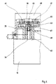
- Figur 1
- eine Aufsicht auf den Aufnahmebehälter, rechts der Mittellinie teilweise geschnitten,
- Figur 2
- eine Schnittansicht gemäß der Schnittlinie II-II der Figur 1,
- Figur 3
- eine Schnittansicht gemäß der Schnittlinie III-III der Figur 1,
- Figur 4
- eine Schnittansicht im Bereich einer Anschlußstelle des Batteriebehälters an einer Langfeldleuchte.
- Es sei Bezug genommen auf die Figur 3.
- Ein Behälter 10 ist gebildet aus einem Behälterunterteil 11 und einem in den Behälterunterteil eingefügten Abdeckteil 12, der, wie ersichtlich, zwei Stufen 13 und 14 aufweist, die der Form eines aus mehreren Batterien 15 bestehenden Batteriepacks 16 angepaßt ist. Das Behälterteil 12 ist als Napfteil ausgebildet; es besitzt anschließend an die Stufen 13 und 14 einen ebenen Bodenbereich 17 und eine umlaufende Wand 18, die wie aus Figur 2 ersichtlich, von der Wandung 19 des Unterteils 11 umfaßt wird. Auf der Oberfläche des ebenen Bereiches 17 befindet sich eine Abdeckplatte 20, an deren in der Zeichnung links dargestellten bzw. befindlichen Ende zwei Nasen 21 und 22 angeformt sind.
- Es nun Bezug genommen auf die Figur 2.
- In dem ebenen Bereich 17 befinden sich zwei nebeneinander liegende Vertiefungen 23 und 24, die eine Zylinderform aufweisen und an ihrem Bodenteil (nur bei der Vertiefung 23 dargestellt) 25 eine mit einer Stufe 26 versehene Öffnung 27 aufweisen, durch die ein an die Öffnung 27 angepaßter Steckerstift 28 hindurchgreift; der Steckerstift 28 besitzt eine umlaufende Leiste 29, die gegen die Stufung 26 anschlägt. Der Steckerstift besitzt im Bereich der Vertiefung ein außerhalb der Bodenwand 25 befindliche umlaufende Rille 30, in die Sprengringfeder 31 eingreift, die eine kegel- oder tellerförmige Form besitzt. Wie aus der Figur 1 ersichtlich, die einen Einblick in die Vertiefung 24 gestattet, besitzt der Ring 31 an seinem nenradius mehrere Finger 32, die durch Öffnungen 33 voneinander getrennt sind; diese Finger 32 wirken als Federelemente und drücken die Leiste 29 gegen die Stufung 26, da die Finger 32 an die entsprechende Wand der Rille 30 des Steckerstiftes 28 andrücken.
- Der Steckerstift 28 besitzt in dem Bereich außerhalb des Ringes 31 einen Abschnitt 34 mit größerem und einen Abschnitt 35 mit kleinerem Durchmesser; der Grund für diese beiden Abschnitte 34 und 35 wird anhand der Figur 4 erläutert.
- Zwischen den beiden Vertiefungen 23 und 24 befindet sich eine in Abstand zu dem Bereich 17 und parallel dazu verlaufende Zwischenwand 36, die zwei Schlitze 37 und 38 aufweist, in die Vorsprünge 39 und 40 an der Abdeckplatte 20 eingreifen und durch die die Abdeckplatte geführt ist. Man erkennt in der Figur 1 den Schlitz 38, in den ein Vorsprungpaar 40 eingreift und darin geführt ist. Der Vorsprung 40 ist in Figur 2 als ein Vorsprung gezeichnet; tatsächlich sind zwei Vorsprünge hintereinander vorhanden, die zu einem Verdrehschutz für die Abdeckplatte 20 dienen. Das freie Ende der Vorsprünge 39 und 40 hintergreift mit Nasen 41 und 42 die Zwischenwand 36, so daß ein Herausnehmen und Abheben der Abdeckplatte verhindert ist.
- Das Teil 12 ist mit mehreren Schrauben 43 bis 45 am Gehäuseunterteil 11 festgeschraubt, wobei, wie aus Figur 2 ersichtlich ist, kanalförmige Rillen 46 vorgesehen sind, durch die die Schrauben 43 (siehe Figur 2), 44 und 45 eingeführt werden können; im Unterteil 11 befinden sich Löcher 47, in die die Schrauben 43 bis 45 eingeschraubt werden können. Die Figur 1 ein solches Gewindeloch 47.
- Am freien inneren Ende des Steckerstiftes 28 ist ein Kabelschuh 48 mit einer Schraube 49 festgeschraubt; es ist auch bei dem in der Vertiefung 24 vorhandenen Steckerstift der Fall. Man erkennt diesen Kabelschuh 50 in der Figur 2.
- Das Unterteil 11 besitzt an seinem freien Flanschrand eine umlaufende Rille 51, in die eine Dichtung 52 eingesetzt ist, die mit einer entsprechenden Dichtung an einem nicht näher dargestellten Gerät zusammenwirkt.
- Zwischen den beiden Vorsprüngen bzw. Vorsprungpaare 39 und 40 befindet sich eine Schraubendruckfeder 53, die mit ihrem einen Ende an einer dem Abdeckteil 12 zugeordneten Wandung 54 und mit ihrem anderen Ende an einer der Abdeckplatte 20 angeformten Wandung 55 zum Anliegen kommt; dadurch wird die Abdeckplatte 20 von der Feder 53 dauernd in Pfeilrichtung P beaufschlagt. Die Wandung 55 befindet sich, wie aus Figur 2 ersichtlich, in dem Bereich, der von der Zwischenwandung 36 und den Vertiefungen 23 und 24 begrenzt ist.
- Die Figur 4 zeigt die Montage des Batteriebehälters 10 an einer Leuchte 60. An der Leuchte 60 ist mittels Schrauben 61 eine Hülse 62 festgeschraubt - für jeden Steckerstift je eine, insgesamt also zwei - in der eine Anschlußbuchse 63 aufgenommen ist. An der Anschlußbuchse 63 schließt ein Kabel 64 an, welches zu einer nicht näher dargestellten Leuchtstofflampe führt. Zu der Hülse 62 mit einem Hülsenflansch 65 gehört ein Fixierstück 66, welches ins Innere der Hülse 62 zum Teil eingreift und mittels der Schrauben 61 an der Leuchte 60 fixiert ist. Das Buchsenelement 63 befindet sich zwischen dem Fixierstück 66 und der Hülse 62. Innerhalb des Buchsenelementes 63 ist eine sacklochartige Öffnung 67 vorgesehen, in der sog. Multilamellenkontakte 68 eingesetzt sind. Der Bereich 35 des Steckerstiftes mit dem verringerten Querschnitt greift in die Buchse bzw. in das Sackloch 67 und kontaktiert mit den Multilamellenkontakten 68. Das freie Ende der Hülse 62 umfaßt auf einer Länge l den Abschnitt 34 des Steckerstiftes dergestalt, daß zwischen der Innenfläche der Hülse 62 und der Außenfläche des Steckerstiftes 34 ein durchschlagsicherer Luftspalt gebildet ist und zwar bevor eine elektrisch leitende Kontaktierung der Buchse 68 mit dem Steckerstift erfolgt ist.
- Die Nasen 21 und 22 wirken mit einem an der Leuchte vorhandenen, in der Zeichnung nicht dargestellten Anschlag zusammen, dergestalt, daß dieser Anschlag die Abdeckplatte 20 in Pfeilrichtung P1 entgegen der Kraft der Feder zurückschiebt; dadurch werden die Steckerstifte freigelegt und können mit den Buchsenelementen kontaktiert werden. Die Montage bzw. der Einbau des Batteriebehälters hat dann so zu erfolgen, daß die Nasen am Anschlag 21 anliegen.
Claims (12)
- An einem Gehäuse eines elektrischen Gerätes, insbesondere einer Langfeldleuchte, befestigbarer Aufnahmebehälter für wenigstens eine Batterie zur Stromversorgung des Gerätes, mit einem Behälterunterteil und einem -oberteil, die miteinander dicht verbunden sind, und mit Anschlußelementen, die mit korrespondierenden Anschlußelementen des Gerätes beim Befestigen verbindbar sind, dadurch gekennzeichnet, daß der Behälter (10) an einer Seitenwand sacklochartige Vertiefungen (23, 24), die zur Außenseite hin offen sind, aufweist, in denen sich Anschlußelemente (28) befinden, und daß im Bereich der Vertiefungen (23, 24) eine Abdeckplatte (20) vorgesehen ist, die entgegen der Kraft einer Federanordnung (53) verschiebbar ist, wobei sie in einer ersten Stellung die Vertiefungen (23, 24) abdeckt und in einer zweiten Stellung freigibt.
- Aufnahmebehälter nach Anspruch 1, dadurch gekennzeichnet, daß am Gerät ein Anschlag vorgesehen ist, gegen den die Abdeckplatte (20) während des Befestigens des Batteriebehälters (10) am Gerät anschlägt und der die Abdeckplatte (20) in die zweite Stellung verschiebt.
- Aufnahmebehälter nach einem der vorherigen Ansprüche, dadurch gekennzeichnet, daß senkrecht an der Abdeckplatte (20) und in Abstand zueinander zwei Vorsprünge (39, 40) oder zwei Vorsprungpaare (39, 40) angeformt sind, die in Führungsausnehmungen (37, 38) am Behälter (10) eingreifen und dadurch die Abdeckplatte (20) beim Verschieben führen.
- Aufnahmebehälter nach einem der vorherigen Ansprüche, dadurch gekennzeichnet, daß zwischen den Vorsprüngen oder Vorsprungpaaren (39, 40) die Federanordnung (53) vorgesehen ist, deren eines Ende an einer Wandung (55) an der Abdeckplatte und deren anderes Ende an einer Wandung (54) am Behälter anliegen.
- Aufnahmebehälter nach Anspruch 4, dadurch gekennzeichnet, daß die Feder eine Schraubendruckfeder ist.
- Aufnahmebehälter nach einem der vorherigen Ansprüche, dadurch gekennzeichnet, daß die Abdeckplatte (20) wenigstens eine Nase (21, 22) auf der den Vorsprüngen (39, 40) entgegengesetzten Seite aufweist.
- Aufnahmebehälter nach einem der vorherigen Ansprüche, dadurch gekennzeichnet, daß die Anschlußelemente am Batteriebehälter (10) Steckerstifte (28) oder Buchsenelemente sind, die in Buchsenelemente (63) oder Steckerstifte am Gerät einsteckbar sind.
- Aufnahmebehälter nach Anspruch 7, dadurch gekennzeichnet, daß die Buchsenelemente (63) von einer diese überragenden Hülse (62) aus isolierendem Material umgeben sind, dergestalt, daß vor dem Kontaktieren der Steckerstifte (34) mit den Buchsenelementen (63) zwischen der Hülse und dem Steckerstift ein dem Ex- bzw. Schlagwettervorschriften entsprechender druckfester Luftspalt gebildet ist.
- Aufnahmebehälter nach Anspruch 7, bei dem die Anschlußelemente Steckerstifte sind, dadurch gekennzeichnet, daß jeder der den Boden der Vertiefungen durchgreifende Steckerstifte (34) am Boden der Vertiefung (23, 24) auf der Behälterinnenseite mittels einer Leiste (29) und auf der Behälteraußenseite oder Bodenseite der Vertiefung mittels eines Federelementes (31) fixiert ist.
- Aufnahmebehälter nach Anspruch 9, dadurch gekennzeichnet, daß das Federelement (31) als etwa tellerförmiger Ring ausgebildet ist, dessen Innenrand Federfinger (32) aufweist, die in eine umlaufende Rille (30) am Steckerstift (28) eingeschnappt sind und den Steckerstift (28) nach außen beaufschlagen und dadurch die Leiste (29) gegen einen Rücksprung (26) an der Behälterinnenseite drücken.
- Aufnahmebehälter nach Anspruch 10, dadurch gekennzeichnet, daß im Behälterinneren an jedem Steckerstift (28) ein Kabelschuh (48, 50) befestigt ist, an dem ein Verbindungsleiter zu der wenigstens einen Batterie angeschlossen ist.
- Aufnahmebehälter nach einem der vorherigen Ansprüche, dadurch gekennzeichnet, daß der Steckerstift (28) an seinem freien Ende einen Bereich (35) verringerten Durchmessers aufweist, der in das Buchsenelement (63) einfügbar ist.
Applications Claiming Priority (2)
| Application Number | Priority Date | Filing Date | Title |
|---|---|---|---|
| DE4323891 | 1993-07-16 | ||
| DE4323891A DE4323891A1 (de) | 1993-07-16 | 1993-07-16 | Aufnahmebehälter für wenigstens eine Batterie |
Publications (2)
| Publication Number | Publication Date |
|---|---|
| EP0638963A1 EP0638963A1 (de) | 1995-02-15 |
| EP0638963B1 true EP0638963B1 (de) | 1997-03-05 |
Family
ID=6492986
Family Applications (1)
| Application Number | Title | Priority Date | Filing Date |
|---|---|---|---|
| EP94110714A Expired - Lifetime EP0638963B1 (de) | 1993-07-16 | 1994-07-09 | Aufnahmebehälter für wenigstens eine Batterie |
Country Status (4)
| Country | Link |
|---|---|
| EP (1) | EP0638963B1 (de) |
| AT (1) | ATE149747T1 (de) |
| DE (2) | DE4323891A1 (de) |
| NO (1) | NO311160B1 (de) |
Families Citing this family (1)
| Publication number | Priority date | Publication date | Assignee | Title |
|---|---|---|---|---|
| DE102010022530A1 (de) | 2010-06-02 | 2011-12-08 | Siemens Aktiengesellschaft | Feldgerät zur Prozessinstrumentierung |
Family Cites Families (12)
| Publication number | Priority date | Publication date | Assignee | Title |
|---|---|---|---|---|
| GB586039A (en) * | 1944-06-21 | 1947-03-05 | Oldham & Son Ltd | Improvements in or relating to a device for protecting electrical contacts against unauthorised access |
| DE1775271U (de) * | 1957-03-27 | 1958-10-09 | Kopp Fa Heinrich | Elektrischer installationsstecker. |
| SU546970A1 (ru) * | 1975-10-06 | 1977-02-15 | Куйбышевский Завод "Электрощит" | Шкаф комплексного распределительного устройства |
| SU851582A1 (ru) * | 1979-11-28 | 1981-07-30 | Предприятие П/Я А-1701 | Шкаф с выкатным элементом |
| DE8024588U1 (de) * | 1980-09-13 | 1981-01-22 | Deutsche Bundesbahn, Vertreten Durch Das Bundesbahn-Zentralamt Minden, 4950 Minden | Batterieblock fuer warnleuchten |
| DE3133986A1 (de) * | 1981-08-27 | 1983-03-10 | Eschweiler Bergwerks-Verein AG, 5120 Herzogenrath | Handleuchte |
| DE3248256C3 (de) * | 1982-12-28 | 1996-01-18 | Unimet Gmbh | Kontaktstift |
| DE8625125U1 (de) * | 1986-09-19 | 1986-11-20 | Siemens AG, 1000 Berlin und 8000 München | Elektrische Kontaktiervorrichtung mit Kontaktschutzeinrichtung |
| DE3810210A1 (de) * | 1988-03-25 | 1989-10-05 | Grote & Hartmann | Elektrische miniaturisierte rundsteckkontakte mit rundsteckhuelse und rundsteckstift |
| DE3833725A1 (de) * | 1988-10-04 | 1990-04-05 | Sachtler Kommunikationstech | Tragbares batteriegehaeuse fuer leuchten |
| US4880712A (en) * | 1989-03-08 | 1989-11-14 | Motorola, Inc. | Battery housing |
| DE9305901U1 (de) * | 1993-04-20 | 1993-07-08 | Bormann, Hans-Joachim, 86356 Neusäß | Kunststoffgehäuse |
-
1993
- 1993-07-16 DE DE4323891A patent/DE4323891A1/de not_active Withdrawn
-
1994
- 1994-07-09 DE DE59401892T patent/DE59401892D1/de not_active Expired - Lifetime
- 1994-07-09 EP EP94110714A patent/EP0638963B1/de not_active Expired - Lifetime
- 1994-07-09 AT AT94110714T patent/ATE149747T1/de not_active IP Right Cessation
- 1994-07-15 NO NO19942677A patent/NO311160B1/no not_active IP Right Cessation
Also Published As
| Publication number | Publication date |
|---|---|
| NO311160B1 (no) | 2001-10-15 |
| EP0638963A1 (de) | 1995-02-15 |
| NO942677L (no) | 1995-01-17 |
| DE59401892D1 (de) | 1997-04-10 |
| NO942677D0 (no) | 1994-07-15 |
| DE4323891A1 (de) | 1995-01-19 |
| ATE149747T1 (de) | 1997-03-15 |
Similar Documents
| Publication | Publication Date | Title |
|---|---|---|
| DE19738772B4 (de) | Steckvorrichtung | |
| WO2007006554A1 (de) | Explosionsgeschützter steckverbinder | |
| WO1994024725A1 (de) | Modul zum anschluss von aktoren und/oder sensoren | |
| DE19857087C2 (de) | Elektrischer Verbinder für Kraftfahrzeugleuchte | |
| DE10008932A1 (de) | Elektrischer Stecker | |
| EP0082469B1 (de) | Gehäuse zur Aufnahme der zur Beschaltung einer Magnetspule eines Hydraulikventils oder dgl. erforderlichen elektrischen Bauteile | |
| EP1139493A2 (de) | Elektrischer Verbinder zum Anschluss von elektrischen Leitern an ein elektrisches Gerät | |
| EP0638963B1 (de) | Aufnahmebehälter für wenigstens eine Batterie | |
| DE202018105607U1 (de) | Leuchtenanschluss und Leuchtenband | |
| DE9204291U1 (de) | Kabelverschraubung | |
| EP0399205B1 (de) | Stellungsgeber für eine schlagwettergeschützte, elektrische Steckverbindung | |
| DE69603884T2 (de) | Einrichtung zum Montieren einer Lampe | |
| EP0561317B1 (de) | Explosionsgeschütztes Gerät, insbesondere Leuchte | |
| EP0378065B1 (de) | Gehäuseteil mit angesetztem Stecker | |
| EP0344628A1 (de) | Explosionsgeschützte Fassung für Zweistift-Leuchtstofflampen | |
| DE3513504C2 (de) | ||
| EP0009769B1 (de) | Vorrichtung zum Anschliessen eines Abzweigleiters | |
| DE10210635B4 (de) | Explosionsgeschütztes Gehäuse mit modularem Vorsatzgehäuse | |
| DE3513502C2 (de) | ||
| DE29605165U1 (de) | Anschlußsystem für mehrere elektrische Bauteile | |
| EP0240882B1 (de) | Explosions- bwz. schlagwettergeschützte Kupplungssteckvorrichtung für Steuerleitungen | |
| DE3150651C1 (de) | Elektrische Mehrfach-Steckdose | |
| EP0111692B1 (de) | Steckerverbindung, insbesondere für elektrische und elektronische Geräte | |
| DE202025102463U1 (de) | Schutzkontaktsteckdose | |
| DE9007606U1 (de) | Fassung für eine Einstiftsockel-Kompaktleuchtstofflampe |
Legal Events
| Date | Code | Title | Description |
|---|---|---|---|
| PUAI | Public reference made under article 153(3) epc to a published international application that has entered the european phase |
Free format text: ORIGINAL CODE: 0009012 |
|
| AK | Designated contracting states |
Kind code of ref document: A1 Designated state(s): AT DE FR GB NL SE |
|
| 17P | Request for examination filed |
Effective date: 19950403 |
|
| GRAG | Despatch of communication of intention to grant |
Free format text: ORIGINAL CODE: EPIDOS AGRA |
|
| 17Q | First examination report despatched |
Effective date: 19960402 |
|
| RAP1 | Party data changed (applicant data changed or rights of an application transferred) |
Owner name: CEAG SICHERHEITSTECHNIK GMBH |
|
| GRAH | Despatch of communication of intention to grant a patent |
Free format text: ORIGINAL CODE: EPIDOS IGRA |
|
| GRAH | Despatch of communication of intention to grant a patent |
Free format text: ORIGINAL CODE: EPIDOS IGRA |
|
| GRAA | (expected) grant |
Free format text: ORIGINAL CODE: 0009210 |
|
| AK | Designated contracting states |
Kind code of ref document: B1 Designated state(s): AT DE FR GB NL SE |
|
| REF | Corresponds to: |
Ref document number: 149747 Country of ref document: AT Date of ref document: 19970315 Kind code of ref document: T |
|
| GBT | Gb: translation of ep patent filed (gb section 77(6)(a)/1977) |
Effective date: 19970305 |
|
| REF | Corresponds to: |
Ref document number: 59401892 Country of ref document: DE Date of ref document: 19970410 |
|
| ET | Fr: translation filed | ||
| PLBE | No opposition filed within time limit |
Free format text: ORIGINAL CODE: 0009261 |
|
| STAA | Information on the status of an ep patent application or granted ep patent |
Free format text: STATUS: NO OPPOSITION FILED WITHIN TIME LIMIT |
|
| 26N | No opposition filed | ||
| REG | Reference to a national code |
Ref country code: GB Ref legal event code: IF02 |
|
| PGFP | Annual fee paid to national office [announced via postgrant information from national office to epo] |
Ref country code: GB Payment date: 20030612 Year of fee payment: 10 |
|
| PGFP | Annual fee paid to national office [announced via postgrant information from national office to epo] |
Ref country code: AT Payment date: 20030613 Year of fee payment: 10 |
|
| PGFP | Annual fee paid to national office [announced via postgrant information from national office to epo] |
Ref country code: NL Payment date: 20030619 Year of fee payment: 10 |
|
| PGFP | Annual fee paid to national office [announced via postgrant information from national office to epo] |
Ref country code: FR Payment date: 20030702 Year of fee payment: 10 |
|
| PGFP | Annual fee paid to national office [announced via postgrant information from national office to epo] |
Ref country code: SE Payment date: 20030703 Year of fee payment: 10 |
|
| PG25 | Lapsed in a contracting state [announced via postgrant information from national office to epo] |
Ref country code: GB Free format text: LAPSE BECAUSE OF NON-PAYMENT OF DUE FEES Effective date: 20040709 Ref country code: AT Free format text: LAPSE BECAUSE OF NON-PAYMENT OF DUE FEES Effective date: 20040709 |
|
| PG25 | Lapsed in a contracting state [announced via postgrant information from national office to epo] |
Ref country code: SE Free format text: LAPSE BECAUSE OF NON-PAYMENT OF DUE FEES Effective date: 20040710 |
|
| PG25 | Lapsed in a contracting state [announced via postgrant information from national office to epo] |
Ref country code: NL Free format text: LAPSE BECAUSE OF NON-PAYMENT OF DUE FEES Effective date: 20050201 |
|
| EUG | Se: european patent has lapsed | ||
| GBPC | Gb: european patent ceased through non-payment of renewal fee |
Effective date: 20040709 |
|
| PG25 | Lapsed in a contracting state [announced via postgrant information from national office to epo] |
Ref country code: FR Free format text: LAPSE BECAUSE OF NON-PAYMENT OF DUE FEES Effective date: 20050331 |
|
| NLV4 | Nl: lapsed or anulled due to non-payment of the annual fee |
Effective date: 20050201 |
|
| REG | Reference to a national code |
Ref country code: FR Ref legal event code: ST |
|
| PGFP | Annual fee paid to national office [announced via postgrant information from national office to epo] |
Ref country code: DE Payment date: 20120731 Year of fee payment: 19 |
|
| REG | Reference to a national code |
Ref country code: DE Ref legal event code: R119 Ref document number: 59401892 Country of ref document: DE Effective date: 20140201 |
|
| PG25 | Lapsed in a contracting state [announced via postgrant information from national office to epo] |
Ref country code: DE Free format text: LAPSE BECAUSE OF NON-PAYMENT OF DUE FEES Effective date: 20140201 |