EP0638974A1 - Etanchéité d'entrée de câble dans la zone d'entrée de câble d'un accessoire de câble - Google Patents
Etanchéité d'entrée de câble dans la zone d'entrée de câble d'un accessoire de câble Download PDFInfo
- Publication number
- EP0638974A1 EP0638974A1 EP94112367A EP94112367A EP0638974A1 EP 0638974 A1 EP0638974 A1 EP 0638974A1 EP 94112367 A EP94112367 A EP 94112367A EP 94112367 A EP94112367 A EP 94112367A EP 0638974 A1 EP0638974 A1 EP 0638974A1
- Authority
- EP
- European Patent Office
- Prior art keywords
- cable entry
- cable
- seal
- ring seal
- ring
- Prior art date
- Legal status (The legal status is an assumption and is not a legal conclusion. Google has not performed a legal analysis and makes no representation as to the accuracy of the status listed.)
- Granted
Links
- 238000007789 sealing Methods 0.000 title claims description 29
- 239000013013 elastic material Substances 0.000 claims abstract description 3
- 238000003780 insertion Methods 0.000 claims description 5
- 230000037431 insertion Effects 0.000 claims description 5
- 230000006835 compression Effects 0.000 claims description 4
- 238000007906 compression Methods 0.000 claims description 4
- 229920001971 elastomer Polymers 0.000 claims description 4
- 239000004519 grease Substances 0.000 claims 1
- 239000003566 sealing material Substances 0.000 claims 1
- 229920002379 silicone rubber Polymers 0.000 claims 1
- 239000004945 silicone rubber Substances 0.000 claims 1
- 238000003825 pressing Methods 0.000 description 4
- 230000006978 adaptation Effects 0.000 description 3
- 238000005452 bending Methods 0.000 description 3
- 239000000463 material Substances 0.000 description 3
- 239000004033 plastic Substances 0.000 description 2
- 230000000694 effects Effects 0.000 description 1
- 239000000806 elastomer Substances 0.000 description 1
- 239000004744 fabric Substances 0.000 description 1
- 230000007774 longterm Effects 0.000 description 1
- 238000000034 method Methods 0.000 description 1
- 239000003921 oil Substances 0.000 description 1
- 230000002035 prolonged effect Effects 0.000 description 1
- 230000000717 retained effect Effects 0.000 description 1
Images

Classifications
-
- H—ELECTRICITY
- H02—GENERATION; CONVERSION OR DISTRIBUTION OF ELECTRIC POWER
- H02G—INSTALLATION OF ELECTRIC CABLES OR LINES, OR OF COMBINED OPTICAL AND ELECTRIC CABLES OR LINES
- H02G15/00—Cable fittings
- H02G15/013—Sealing means for cable inlets
Definitions
- the invention relates to a cable entry seal, consisting of a ring seal made of elastic material and an adapted insertion opening in the cable entry area of a cable assembly.
- Such cable entry seals are very well known, e.g. from the European patent EP 0 402 653 A2. There, a cable entry seal made of deformable material in the form of an annular plug made of a foamed elastomer is described, which is inserted into a cable entry opening in the form of a sleeve of a housing.
- the object of the present invention is now to find a cable entry seal with which the abovementioned disadvantages are largely eliminated, primarily a relatively large cable diameter range is to be covered with little effort, a long-term effective retensioning capability must be provided, and the seal is thus so must be designed so that it can be detached and reused without disassembly.
- the problem is now solved with a cable entry seal of the type described above in that the cable entry opening is tapered in that the ring seal is adapted at least on the outside to the conical shape of the cable entry opening, that at the wide end of the cable entry opening one for one in the axial direction pressure medium acting on the ring seal is arranged.
- the conical ring seal is preferably initially at the narrow end closed formed as a cap, so that unused cable entry openings are initially closed when inserting such a ring seal. Additional elements are therefore not required and only the cap has to be cut off if necessary. At the same time, as a result of the conical design, a rough adaptation to the diameter of the cable to be inserted can be carried out by cutting off at a corresponding point. If the conical ring seal is also provided with a longitudinal slot, it can also be used with uncut cables, but then the cable entry level of the cable set must also be cut. Due to the axial contact pressure with the help of the pressure medium, the longitudinal slot is closed again due to the compression pressure. The sealing effect in the parting surfaces is increased if the ring seal is wetted with suitable greases or oils. This reduces the friction when pressing in and, in addition, better filling of narrow gaps and grooves is possible due to the better sliding properties.
- Such a cable entry seal according to the invention can be used in any type of sleeve if the required counter surfaces are correspondingly conical.
- the cable entry opening must have a conical or conical configuration which is adapted to the ring seal, so that it can be pressed in along this conical surface.
- Such training can take place both in divided and in undivided cable entry areas.
- a combination is also possible, i.e. within a cable entry area, e.g. Both split and undivided cable entry openings can be arranged in the end face of a sealing body of a sleeve. In this way, cut and uncut cables can be inserted in such an insertion area.
- the tapered cable entries are preferably designed so that the wide end is inside the cable assembly is located and the narrow end points to the outside, whereby the pressing area inside the sleeve is also protected.
- the cable entry openings are expediently designed as protruding connecting pieces with a length such that the inserted cables are supported at the free ends of the connecting pieces in the event of bending loads. This particularly keeps the lateral forces away from the area of the cable entry seal.
- the problem of the seal between the ring seal and the profile seal of the parting plane is solved in that the profile seal and the ring seal, in particular one with a laterally formed rib, are pressed together in a common groove running parallel to the conical shape.
- an annular pressure screw can consist of two half parts which are connected to one another via a film hinge, locking or guide cams.
- the half-shells of a cable sleeve or a sealing body made of two halves, as they can also be used, are pressed against one another in a manner known per se, the mutual sealing being effected with a profile seal.
- a sealing body 1 is shown as an exemplary embodiment for a cable entry area, which can be used on the end face of a socket pipe.
- This sealing body 1 is longitudinally divided in the parting plane 4, so that it can also be used in the introduction of uncut cables.
- a cable entry opening 5 is formed in this parting plane 4, which protrudes in the form of a socket from the front side of the sealing body 1.
- the conical ring seal 7, which is still closed at the front, can be seen in this neck-shaped cable entry opening 5.
- additional cable entry openings 6 can be arranged in this sealing body 1, through which only cut cables can be inserted. Since they are not divided lengthways.
- the ring seals 7 used can also be seen here. It is also possible that several cable entries are provided in the parting plane 4. A sleeve pipe is clamped over the sealing body 1, a sealing insert being inserted into the sealing groove 8 for sealing.
- FIG. 2 now illustrates the arrangement of the conical ring seal 7, which is inserted in a divided, conically shaped and divided cable entry opening 5.
- the flanges 3 and 4 can be seen, the profile seal 10 with the ring seal 7, but preferably an attached rib 12, being tightly pressed together in a common sealing groove 11, which also runs parallel to the conical shape of the ring seal 7.
- the ring seal 7 is also shown as a cap-shaped, closed part, the section being carried out at the point corresponding to the cable diameter if necessary, depending on the diameter of the cable to be inserted.
- a thread 21 is cut into which the pressure medium, for example in the form of a ring nut 14, can be screwed.
- a compression spring insert 15 is inserted, which is used to maintain a certain contact pressure.
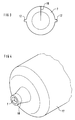
- FIG. 3 shows a conical ring seal 7 in a front view, lateral ribs 12 being additionally formed here, which are used to seal against the profile seals of the longitudinal seal of the cable sleeve or of the sealing body. It can also be seen that the ring seal 7 has a longitudinal slot 16, so that this ring seal 7 can also be used with uncut cables.
- FIG. 4 shows that a ring seal 7 according to the invention can also be used in uncut insertion areas of a cable sleeve 17, this corresponding to the cable entries 6 already described in FIG. 1.
- this cable entry is designed as a socket 18, which is long enough that an inserted cable can be supported at the outermost end of the ring when subjected to bending loads. As a result, the bending loads are kept away from the sealing area.
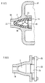
- FIG. 5 now illustrates in a cross section the explanations according to FIG. 4, from which the conditions already described can be seen again.
- the conical and cap-shaped ring seal 7 is pressed into the conical cable entry opening 22 by means of an annular pressure nut 14.
- a spring force storage of the material in the region 20 is possible by the pressing.
- Line 19 indicates that the ring seal 7 can be cut up to here; this corresponds to the maximum insertable cable diameter.
- FIG. 6 shows that other pressure means can also be used, for example a pressure plate 23 which can be divided and which can be pressed against the ring seal 7 by means of screws 25.
- An extension 24 enables better guidance within the cable entry opening.
- Compression spring inserts can also be used here, as already described above. This example is intended to illustrate that other exemplary embodiments are conceivable with which the same mode of action can be achieved.
Landscapes
- Cable Accessories (AREA)
- Installation Of Indoor Wiring (AREA)
- Insulated Conductors (AREA)
- Air Conditioning Control Device (AREA)
Applications Claiming Priority (2)
| Application Number | Priority Date | Filing Date | Title |
|---|---|---|---|
| DE4326973 | 1993-08-11 | ||
| DE4326973 | 1993-08-11 |
Publications (2)
| Publication Number | Publication Date |
|---|---|
| EP0638974A1 true EP0638974A1 (fr) | 1995-02-15 |
| EP0638974B1 EP0638974B1 (fr) | 1997-06-11 |
Family
ID=6494954
Family Applications (1)
| Application Number | Title | Priority Date | Filing Date |
|---|---|---|---|
| EP94112367A Expired - Lifetime EP0638974B1 (fr) | 1993-08-11 | 1994-08-08 | Etanchéité d'entrée de câble dans la zone d'entrée de câble d'un accessoire de câble |
Country Status (7)
| Country | Link |
|---|---|
| US (1) | US5504276A (fr) |
| EP (1) | EP0638974B1 (fr) |
| AT (1) | ATE154475T1 (fr) |
| DE (1) | DE59403090D1 (fr) |
| DK (1) | DK0638974T3 (fr) |
| ES (1) | ES2103522T3 (fr) |
| GR (1) | GR3024432T3 (fr) |
Cited By (1)
| Publication number | Priority date | Publication date | Assignee | Title |
|---|---|---|---|---|
| WO1996036096A1 (fr) * | 1995-05-10 | 1996-11-14 | Walter Friedl | Boite de jonction |
Families Citing this family (7)
| Publication number | Priority date | Publication date | Assignee | Title |
|---|---|---|---|---|
| DE19536456C2 (de) * | 1995-09-29 | 1998-07-02 | Hirschmann Richard Gmbh Co | Gehäusedichtung für Leitungsdurchführungsöffnungen |
| US6443457B1 (en) * | 2000-03-31 | 2002-09-03 | Avaya Technology Corp. | Cable sealing device for various cable gauges |
| FR2823609B1 (fr) | 2001-04-12 | 2003-05-30 | Nexans | Joint d'etancheite pour cables |
| US7645946B2 (en) * | 2006-05-15 | 2010-01-12 | Smith Jeffrey M | Two-piece pipe escutcheon |
| CN102971465A (zh) * | 2010-06-29 | 2013-03-13 | 沃尔沃建造设备有限公司 | 用于建筑机械驾驶室顶的防水垫圈 |
| WO2012162497A1 (fr) * | 2011-05-24 | 2012-11-29 | Corning Cable Systems Llc | Rondelle de passe-câble à orifice pour trois câbles |
| CN103391655B (zh) * | 2013-07-12 | 2015-08-05 | 曲颜发 | 电极引出端子 |
Citations (7)
| Publication number | Priority date | Publication date | Assignee | Title |
|---|---|---|---|---|
| GB724596A (en) * | 1952-05-07 | 1955-02-23 | Philips Electrical Ind Ltd | Improvements in or relating to water-tight electric connection boxes |
| US3054847A (en) * | 1960-09-22 | 1962-09-18 | Lee J Colbert | Cable splice enclosure |
| DE1949345A1 (de) * | 1969-09-30 | 1971-04-08 | Siemens Ag | Laengsgeteilte Kabelmuffe fuer Nachrichtenkabel |
| DE7607339U1 (de) * | 1976-03-10 | 1976-07-29 | Siemens Ag, 1000 Berlin Und 8000 Muenchen | Kabelgarnitur mit Kabeleinführung für Kabel mit Aluminiummantel |
| US4255614A (en) * | 1979-03-22 | 1981-03-10 | Channell William H | Method and apparatus for enclosing a cable splice |
| EP0402653A2 (fr) * | 1989-06-13 | 1990-12-19 | Siemens Aktiengesellschaft | Garniture étanche pour entrée de câbles |
| WO1992020077A1 (fr) * | 1991-05-01 | 1992-11-12 | Raychem Corporation | Joint etanche pour cable |
Family Cites Families (12)
| Publication number | Priority date | Publication date | Assignee | Title |
|---|---|---|---|---|
| US2688651A (en) * | 1951-04-10 | 1954-09-07 | Us Rubber Co | Cable joint protector |
| US3056852A (en) * | 1961-03-31 | 1962-10-02 | Leslie W Sachs | Strain relief grommet |
| US3744008A (en) * | 1971-11-23 | 1973-07-03 | Thomas & Betts Corp | Strain relief assembly |
| DE2309649A1 (de) * | 1973-02-27 | 1974-08-29 | Lapp Kg U I | Kabelverschraubung |
| US4033535A (en) * | 1973-05-18 | 1977-07-05 | Eaton Corporation | Strain-relief bushing |
| US4030741A (en) * | 1975-01-20 | 1977-06-21 | Harvey Hubbell, Incorporated | Cord grips |
| US4109911A (en) * | 1975-04-23 | 1978-08-29 | Auken John A Van | Gaming surface contact detecting systems |
| US4350840A (en) * | 1981-03-20 | 1982-09-21 | Ideal Industries, Inc. | Cord grip |
| SU955312A1 (ru) * | 1981-03-30 | 1982-08-30 | за вители ™,, Ю. П тецкий, М. П. KocTeJiKo, Bl Bh.-iMikA B : I и В. К- Каленое |,,.,„,,.,; 5 Я ; 1.;. S ii, лг ; i ,с..,. гi atij; i(/fcii/ | Кабельный ввод |
| US4358079A (en) * | 1981-10-15 | 1982-11-09 | Pass And Seymour, Inc. | Moisture resistant clamp for portable cables |
| US4525000A (en) * | 1984-02-17 | 1985-06-25 | General Signal Corporation | Cable fitting with variable inner diameter grommet assembly |
| US5208427A (en) * | 1992-01-31 | 1993-05-04 | Thomas & Betts Corporation | Connector for terminating electrical cable assemblies of multiple configurations |
-
1994
- 1994-06-07 US US08/257,098 patent/US5504276A/en not_active Expired - Fee Related
- 1994-08-08 EP EP94112367A patent/EP0638974B1/fr not_active Expired - Lifetime
- 1994-08-08 DK DK94112367.1T patent/DK0638974T3/da active
- 1994-08-08 DE DE59403090T patent/DE59403090D1/de not_active Expired - Fee Related
- 1994-08-08 AT AT94112367T patent/ATE154475T1/de not_active IP Right Cessation
- 1994-08-08 ES ES94112367T patent/ES2103522T3/es not_active Expired - Lifetime
-
1997
- 1997-08-13 GR GR970402075T patent/GR3024432T3/el unknown
Patent Citations (7)
| Publication number | Priority date | Publication date | Assignee | Title |
|---|---|---|---|---|
| GB724596A (en) * | 1952-05-07 | 1955-02-23 | Philips Electrical Ind Ltd | Improvements in or relating to water-tight electric connection boxes |
| US3054847A (en) * | 1960-09-22 | 1962-09-18 | Lee J Colbert | Cable splice enclosure |
| DE1949345A1 (de) * | 1969-09-30 | 1971-04-08 | Siemens Ag | Laengsgeteilte Kabelmuffe fuer Nachrichtenkabel |
| DE7607339U1 (de) * | 1976-03-10 | 1976-07-29 | Siemens Ag, 1000 Berlin Und 8000 Muenchen | Kabelgarnitur mit Kabeleinführung für Kabel mit Aluminiummantel |
| US4255614A (en) * | 1979-03-22 | 1981-03-10 | Channell William H | Method and apparatus for enclosing a cable splice |
| EP0402653A2 (fr) * | 1989-06-13 | 1990-12-19 | Siemens Aktiengesellschaft | Garniture étanche pour entrée de câbles |
| WO1992020077A1 (fr) * | 1991-05-01 | 1992-11-12 | Raychem Corporation | Joint etanche pour cable |
Cited By (1)
| Publication number | Priority date | Publication date | Assignee | Title |
|---|---|---|---|---|
| WO1996036096A1 (fr) * | 1995-05-10 | 1996-11-14 | Walter Friedl | Boite de jonction |
Also Published As
| Publication number | Publication date |
|---|---|
| EP0638974B1 (fr) | 1997-06-11 |
| DE59403090D1 (de) | 1997-07-17 |
| DK0638974T3 (da) | 1997-10-20 |
| ES2103522T3 (es) | 1997-09-16 |
| US5504276A (en) | 1996-04-02 |
| GR3024432T3 (en) | 1997-11-28 |
| ATE154475T1 (de) | 1997-06-15 |
Similar Documents
| Publication | Publication Date | Title |
|---|---|---|
| EP0897202B1 (fr) | Connecteur pour câble coaxial | |
| DE69501803T2 (de) | Wasserfeste Dichtung für Verbinder | |
| DE3218751A1 (de) | Dichtungseinrichtung | |
| DE3520199A1 (de) | Potentiometer | |
| DE202017100157U1 (de) | Kugelschnäpper | |
| DE3418978A1 (de) | Kabelverschraubung | |
| DE102017101870A1 (de) | Steckverbindergehäuse | |
| EP0638974B1 (fr) | Etanchéité d'entrée de câble dans la zone d'entrée de câble d'un accessoire de câble | |
| DE3110660A1 (de) | Garnitur fuer das ende eines mittelspannnungs- oder hochspannunskabels | |
| WO2000037821A1 (fr) | Palier en caoutchouc presentant une caracteristique qui varie dans le sens circonferentiel | |
| EP0674375B1 (fr) | Dispositif amovible d'accouplement de deux conducteurs s'alignant entre eux | |
| DE60302953T2 (de) | Verbinder für zwei elektrische Energiekabel und Verbindung mit einem solchen Verbinder | |
| DE9400555U1 (de) | Anschlußteil für einen Betätigungszug | |
| EP0402653A2 (fr) | Garniture étanche pour entrée de câbles | |
| DE102014222879A1 (de) | Abdeckelement für einen elektrischen Verbinder | |
| EP0638975B1 (fr) | Extrémité de manchon à pluralité d'entrées subdivisées de câbles | |
| DE3341029A1 (de) | Steckverbindung fuer mit einem druckmittel beaufschlagbare systeme | |
| DE4407514C2 (de) | Abzweig- oder Verbindungsmuffe für Erdkabel im Niederspannungsbereich | |
| EP0703394A1 (fr) | Collier de serrage | |
| DE3101519A1 (de) | Leitendes dichtungsprofil zur herstellung einer hochfrequenz-dichtung an trennfugen zwischen metallischen gehaeuseteilen | |
| DE20310503U1 (de) | Meßpunkt-Bolzen | |
| DE3937888C2 (fr) | ||
| DE10200018A1 (de) | Spieleinstellbares Gleitlager und Fluidzylinder mit einem solchen Gleitlager | |
| DE1815801A1 (de) | Vorrichtung zur elektrischen Verbindung der Innenleiter von Koaxialkabeln | |
| DE2252026A1 (de) | Anschlusseinrichtung fuer koaxialkabel |
Legal Events
| Date | Code | Title | Description |
|---|---|---|---|
| PUAI | Public reference made under article 153(3) epc to a published international application that has entered the european phase |
Free format text: ORIGINAL CODE: 0009012 |
|
| AK | Designated contracting states |
Kind code of ref document: A1 Designated state(s): AT BE CH DE DK ES FR GB GR IT LI NL SE |
|
| 17P | Request for examination filed |
Effective date: 19950307 |
|
| 17Q | First examination report despatched |
Effective date: 19960619 |
|
| GRAG | Despatch of communication of intention to grant |
Free format text: ORIGINAL CODE: EPIDOS AGRA |
|
| GRAH | Despatch of communication of intention to grant a patent |
Free format text: ORIGINAL CODE: EPIDOS IGRA |
|
| GRAH | Despatch of communication of intention to grant a patent |
Free format text: ORIGINAL CODE: EPIDOS IGRA |
|
| GRAA | (expected) grant |
Free format text: ORIGINAL CODE: 0009210 |
|
| AK | Designated contracting states |
Kind code of ref document: B1 Designated state(s): AT BE CH DE DK ES FR GB GR IT LI NL SE |
|
| REF | Corresponds to: |
Ref document number: 154475 Country of ref document: AT Date of ref document: 19970615 Kind code of ref document: T |
|
| REG | Reference to a national code |
Ref country code: CH Ref legal event code: NV Representative=s name: SIEMENS SCHWEIZ AG Ref country code: CH Ref legal event code: EP |
|
| REF | Corresponds to: |
Ref document number: 59403090 Country of ref document: DE Date of ref document: 19970717 |
|
| GBT | Gb: translation of ep patent filed (gb section 77(6)(a)/1977) |
Effective date: 19970813 |
|
| ITF | It: translation for a ep patent filed | ||
| ET | Fr: translation filed | ||
| REG | Reference to a national code |
Ref country code: ES Ref legal event code: FG2A Ref document number: 2103522 Country of ref document: ES Kind code of ref document: T3 |
|
| REG | Reference to a national code |
Ref country code: DK Ref legal event code: T3 |
|
| REG | Reference to a national code |
Ref country code: GR Ref legal event code: FG4A Free format text: 3024432 |
|
| PLBE | No opposition filed within time limit |
Free format text: ORIGINAL CODE: 0009261 |
|
| STAA | Information on the status of an ep patent application or granted ep patent |
Free format text: STATUS: NO OPPOSITION FILED WITHIN TIME LIMIT |
|
| 26N | No opposition filed | ||
| PGFP | Annual fee paid to national office [announced via postgrant information from national office to epo] |
Ref country code: FR Payment date: 20010718 Year of fee payment: 8 |
|
| PGFP | Annual fee paid to national office [announced via postgrant information from national office to epo] |
Ref country code: DE Payment date: 20010719 Year of fee payment: 8 Ref country code: SE Payment date: 20010719 Year of fee payment: 8 |
|
| PGFP | Annual fee paid to national office [announced via postgrant information from national office to epo] |
Ref country code: CH Payment date: 20010720 Year of fee payment: 8 Ref country code: GB Payment date: 20010720 Year of fee payment: 8 Ref country code: DK Payment date: 20010720 Year of fee payment: 8 Ref country code: AT Payment date: 20010720 Year of fee payment: 8 |
|
| PGFP | Annual fee paid to national office [announced via postgrant information from national office to epo] |
Ref country code: NL Payment date: 20010723 Year of fee payment: 8 |
|
| PGFP | Annual fee paid to national office [announced via postgrant information from national office to epo] |
Ref country code: GR Payment date: 20010731 Year of fee payment: 8 |
|
| PGFP | Annual fee paid to national office [announced via postgrant information from national office to epo] |
Ref country code: BE Payment date: 20010810 Year of fee payment: 8 |
|
| PGFP | Annual fee paid to national office [announced via postgrant information from national office to epo] |
Ref country code: ES Payment date: 20010906 Year of fee payment: 8 |
|
| REG | Reference to a national code |
Ref country code: GB Ref legal event code: IF02 |
|
| PG25 | Lapsed in a contracting state [announced via postgrant information from national office to epo] |
Ref country code: GB Free format text: LAPSE BECAUSE OF NON-PAYMENT OF DUE FEES Effective date: 20020808 Ref country code: AT Free format text: LAPSE BECAUSE OF NON-PAYMENT OF DUE FEES Effective date: 20020808 |
|
| PG25 | Lapsed in a contracting state [announced via postgrant information from national office to epo] |
Ref country code: SE Free format text: LAPSE BECAUSE OF NON-PAYMENT OF DUE FEES Effective date: 20020809 Ref country code: ES Free format text: LAPSE BECAUSE OF NON-PAYMENT OF DUE FEES Effective date: 20020809 |
|
| PG25 | Lapsed in a contracting state [announced via postgrant information from national office to epo] |
Ref country code: LI Free format text: LAPSE BECAUSE OF NON-PAYMENT OF DUE FEES Effective date: 20020831 Ref country code: DK Free format text: LAPSE BECAUSE OF NON-PAYMENT OF DUE FEES Effective date: 20020831 Ref country code: CH Free format text: LAPSE BECAUSE OF NON-PAYMENT OF DUE FEES Effective date: 20020831 Ref country code: BE Free format text: LAPSE BECAUSE OF NON-PAYMENT OF DUE FEES Effective date: 20020831 |
|
| BERE | Be: lapsed |
Owner name: *SIEMENS A.G. Effective date: 20020831 |
|
| PG25 | Lapsed in a contracting state [announced via postgrant information from national office to epo] |
Ref country code: NL Free format text: LAPSE BECAUSE OF NON-PAYMENT OF DUE FEES Effective date: 20030301 Ref country code: DE Free format text: LAPSE BECAUSE OF NON-PAYMENT OF DUE FEES Effective date: 20030301 |
|
| PG25 | Lapsed in a contracting state [announced via postgrant information from national office to epo] |
Ref country code: GR Free format text: LAPSE BECAUSE OF NON-PAYMENT OF DUE FEES Effective date: 20030305 |
|
| EUG | Se: european patent has lapsed | ||
| GBPC | Gb: european patent ceased through non-payment of renewal fee |
Effective date: 20020808 |
|
| REG | Reference to a national code |
Ref country code: DK Ref legal event code: EBP |
|
| REG | Reference to a national code |
Ref country code: CH Ref legal event code: PL |
|
| PG25 | Lapsed in a contracting state [announced via postgrant information from national office to epo] |
Ref country code: FR Free format text: LAPSE BECAUSE OF NON-PAYMENT OF DUE FEES Effective date: 20030430 |
|
| NLV4 | Nl: lapsed or anulled due to non-payment of the annual fee |
Effective date: 20030301 |
|
| REG | Reference to a national code |
Ref country code: FR Ref legal event code: ST |
|
| REG | Reference to a national code |
Ref country code: ES Ref legal event code: FD2A Effective date: 20030912 |
|
| PG25 | Lapsed in a contracting state [announced via postgrant information from national office to epo] |
Ref country code: IT Free format text: LAPSE BECAUSE OF NON-PAYMENT OF DUE FEES;WARNING: LAPSES OF ITALIAN PATENTS WITH EFFECTIVE DATE BEFORE 2007 MAY HAVE OCCURRED AT ANY TIME BEFORE 2007. THE CORRECT EFFECTIVE DATE MAY BE DIFFERENT FROM THE ONE RECORDED. Effective date: 20050808 |