EP0638976A1 - Extrémité de manchon pour un manchon de câble à pièce d'insertion en matériau élastique - Google Patents
Extrémité de manchon pour un manchon de câble à pièce d'insertion en matériau élastique Download PDFInfo
- Publication number
- EP0638976A1 EP0638976A1 EP94112369A EP94112369A EP0638976A1 EP 0638976 A1 EP0638976 A1 EP 0638976A1 EP 94112369 A EP94112369 A EP 94112369A EP 94112369 A EP94112369 A EP 94112369A EP 0638976 A1 EP0638976 A1 EP 0638976A1
- Authority
- EP
- European Patent Office
- Prior art keywords
- cable
- sleeve
- head according
- pressure
- sealing insert
- Prior art date
- Legal status (The legal status is an assumption and is not a legal conclusion. Google has not performed a legal analysis and makes no representation as to the accuracy of the status listed.)
- Granted
Links
- 238000007789 sealing Methods 0.000 title claims abstract description 52
- 239000012858 resilient material Substances 0.000 title 1
- 230000006835 compression Effects 0.000 claims abstract description 12
- 238000007906 compression Methods 0.000 claims abstract description 12
- 238000003780 insertion Methods 0.000 claims abstract description 11
- 230000037431 insertion Effects 0.000 claims abstract description 11
- 239000013013 elastic material Substances 0.000 claims abstract description 9
- 239000000945 filler Substances 0.000 claims description 2
- 239000000463 material Substances 0.000 description 3
- 238000005452 bending Methods 0.000 description 2
- 239000003566 sealing material Substances 0.000 description 2
- 230000005540 biological transmission Effects 0.000 description 1
- 239000003795 chemical substances by application Substances 0.000 description 1
- 230000000694 effects Effects 0.000 description 1
- 229920001971 elastomer Polymers 0.000 description 1
- 239000000806 elastomer Substances 0.000 description 1
- 210000004907 gland Anatomy 0.000 description 1
- 230000012447 hatching Effects 0.000 description 1
- 230000000717 retained effect Effects 0.000 description 1
Images


Classifications
-
- H—ELECTRICITY
- H02—GENERATION; CONVERSION OR DISTRIBUTION OF ELECTRIC POWER
- H02G—INSTALLATION OF ELECTRIC CABLES OR LINES, OR OF COMBINED OPTICAL AND ELECTRIC CABLES OR LINES
- H02G15/00—Cable fittings
- H02G15/013—Sealing means for cable inlets
Definitions
- the invention relates to a sleeve head for a cable sleeve with a sealing insert made of elastic material and with pressure-generating elements for pressing the sealing insert.
- the object of the invention is to create a socket head in which as many cable entries as possible are provided, the seal being to be handled particularly easily by means of elastic material.
- the task is now solved with a sleeve head for a cable sleeve of the type described above in that the cable sleeve is expanded conically at the end in the insertion area that a conical sealing insert adapted to the insertion area is arranged between two pressure plates that the sealing insert has tapered cable entry openings, and that the sealing insert can be compressed and deformed by the pressure plates by means of pressure-generating elements so that the deformation in the cable entries results in a sealing pressure on the inserted cables.
- a sleeve head and a cable sleeve according to the invention in that the closing and sealing of the cable sleeve in the area of the sleeve head can be carried out simultaneously with a single sealing insert made of elastic material for all cable entry openings.
- the conical design of the cable sleeve at the end and the likewise conical design of the sealing insert on the outer circumference result in advantageous conditions with regard to the compression pressure required for sealing in the cable entry openings. It does not matter whether it is a through sleeve or a pot sleeve.
- the arrangement of the pressure-generating elements acting on the sealing insert results in an axial pressing of the sealing insert, which is made of rubber-elastic material.
- the cable entry openings themselves are also conical, so that a wide range of cable diameters can be covered. It is also useful to arrange the cable entry openings so that they can each be provided with a radially extending slot towards the outer periphery of the sealing insert. In this way, it is possible for the cables to be inserted from the outside into the cable insertion openings of the sealing insert, so that uncut cables can also be used.
- the sealing insert made of rubber-elastic material is designed as a block and inserted between two pressure plates in the sealing area of the cable sleeve, the compression essentially from the outside due to the conical shape of the sleeve end occurs during the axial pressing in by the pressure-generating elements.
- the slots for inserting the cables are arranged radially and are thus directly exposed to the compressive effect from the outer cone.
- the relatively thick gasket insert compensates for the compression pressure within the volume.
- the thickness of the sealing insert is about twice as large as the diameter difference between the maximum and minimum cable diameters that can be inserted into a cable entry and the distance between the cable entries should be at least 1.3 times the largest insertable cable diameter. It is also an object of the invention that cable interception devices are installed in the interior of the cable sleeve at the cable entry openings, which expediently be placed directly on the inner pressure plate so that each cable can be gripped directly at the end of the cable entry. Various variants are proposed for this purpose, in which a cable shield can also be contacted.
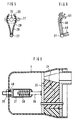
- FIG. 1 shows the basic design of a cable entry with a socket head, in which several cable entry openings are arranged.
- the cable sleeve 1 in the area of the sleeve head which consists of two pressure plates 7 and 8 and an elastic sealing insert 2 in between, has a conical or conical opening that widens outwards.
- the overall also conical sleeve head is inserted, the inner pressure plate 8 being connected at a fixed distance to the outer pressure plate 7, for example with rivet bolts 9.
- FIG. 2 shows the sealing insert 2 used in FIG. 1 in a view from the outside (but without a pressure plate), so that the conical designs of the cable guide openings 3 appear.
- the conical cable entry openings 3 are arranged here in a circle near the outer boundary, so that radial slots 5 for the insertion of the cables, in particular uncut cables, can be guided to the edge of the sealing insert 2.
- the bores 10 for carrying out the connecting elements between the pressure plates can be seen. Section I-I, on which FIG. 1 is based, is also shown.
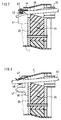
- FIG. 3 shows a socket head with a special screw connection to the socket hood or to the socket cylinder 1.
- the ends of the screw bolts 18 as pressure-generating elements 21 are captively fastened in the socket hood or socket cylinder 1.
- the bolts 18 are guided through the individual parts of the socket head and tightened by screwing on nuts 19.
- the rotationally secured screw bolts 18 each tension a compression spring 20 (coil or disc springs) against a guide 22.
- This resilient arrangement results in addition to the rubber-elastic one Material is a resilient pressure that can be used to compensate for cold flow or changes in volume caused by temperature.
- the opposite hatching of the gasket insert in the figure indicates that in this embodiment the gasket insert is separated, namely the gasket insert is divided into a central part 23 and a ring part 24. This forms a separating surface in which the cable entries 13 are arranged . In this way it is possible to dispense with the slots leading to the outside (such a slot 14 is also shown here), but the printing plates must then also be designed accordingly. This means that assembly is also possible with uncut cables.
- the relevant designs are shown in Figure 4. Here, however, the cylindrical movement range 33 for the outer pressure plate parts 11 and 12 is also indicated in FIG. 3.
- a cable interception device 28 is indicated inside the cable sleeve 1 (only one for the sake of clarity), which is aligned with the cable entry opening 13.
- This cable interception device is attached to a central bolt 27, on which all other cable interception devices can also be attached in a star shape.
- Each of these cable interception devices 28 consists of two clamp legs 30 which enclose the inserted cable and are pressed together by means of a tension band.
- the cable entry openings of the outer pressure plates 11 and 12 are each provided with cylindrical anti-kink connectors 15. This kink protection connector 15 prevents bending loads on the cable from being prevented from the sealing point.
- the separating surface 16 between the central part 11 and the ring part 12 of the outer pressure plate can also be seen in this area.
- FIG. 4 now shows a top view of the conditions of a socket head divided by an approximately circular separating surface 16, the central part 11 and the ring part 12 thereby being created.
- the cable entry openings are now in this separating surface 16 13 arranged around which the cylindrical anti-kink connector 15 extend.
- the screw bolts 18 located in the ring part 12 can be seen.
- positioning devices or stop elements 26 are attached, through which the central part 11 is carried.
- Radially directed fixing elements 25 can also be arranged for the positioning of the individual sleeve head elements with respect to one another.
- the cable entry openings 13 located in a one-piece sealing insert can also be provided with slots 14 directed radially outwards.
- FIG. 5 conveys the configuration of the cable interception device shown in FIG. 3 from the clamp legs 28, which are fastened to the central bolt 27. After receiving a cable 32, the clamp legs 28 are pressed together with a tensioning strap 31 guided through openings 29 and slots 30.
- FIG. 6 A hood sleeve 1 is shown in FIG. 6, in which the pressure-generating element is guided through the hood part. It consists of a centrally arranged bolt 36 which is fastened to the inner pressure plate 35. A spring element 38 ensures a permanent reprint. A sealing ring 40 provides the required seal in the hood housing. In such an embodiment, only one spring element is required if the material and the temperature stress require a pressure device at all.
- FIG. 7 shows a further variant for a cable interception device in the interior of a cable sleeve 1 with a sleeve head and a seal 34 as is the basis of the invention.
- This cable interception device is fastened to the inner pressure plate 35 and consists of an interception ring 41 which is arranged in one piece around all the cable insertion openings.
- this interception ring 41 can by means of screws 43 all cable sheaths 45, in which a cable sheath flap 44 has been formed, are clamped, a contact plate 42 with tears being arranged on the inside of this cable sheath flap 44. If the cable jacket is provided with a screen or is designed as a layer jacket, this screen can be contacted with this interception device at the same time.
- the cable 45 abuts the edge of the cylindrical anti-kink connector 15 in the event of bending loads and that this load is thereby kept away from the sealing point.
- a cable interception device which also consists of a common ring 46 on which a tab 47 is formed with each cable entry. If necessary, these tabs 47 are bent onto the cable sheath 45 and clamped thereon by means of tensioning straps 48, as the partial sectional view of the figure shows. The other conditions regarding the socket head have already been described.
- FIG. 9 again shows an intercepting clamp which is formed from two clamp legs 49, which are fastened in a star shape on the one hand to a central bolt 27 and on the other hand are shaped such that between their ends e.g. a cable jacket rag can be clamped by means of screws 51. Breakthroughs 50 promote grip.
Landscapes
- Cable Accessories (AREA)
- Installation Of Indoor Wiring (AREA)
- Insulating Bodies (AREA)
Applications Claiming Priority (2)
| Application Number | Priority Date | Filing Date | Title |
|---|---|---|---|
| DE4326972 | 1993-08-11 | ||
| DE4326972 | 1993-08-11 |
Publications (2)
| Publication Number | Publication Date |
|---|---|
| EP0638976A1 true EP0638976A1 (fr) | 1995-02-15 |
| EP0638976B1 EP0638976B1 (fr) | 1997-06-11 |
Family
ID=6494953
Family Applications (1)
| Application Number | Title | Priority Date | Filing Date |
|---|---|---|---|
| EP94112369A Expired - Lifetime EP0638976B1 (fr) | 1993-08-11 | 1994-08-08 | Extrémité de manchon pour un manchon de câble à pièce d'insertion en matériau élastique |
Country Status (7)
| Country | Link |
|---|---|
| US (1) | US5502282A (fr) |
| EP (1) | EP0638976B1 (fr) |
| AT (1) | ATE154477T1 (fr) |
| DE (1) | DE59403092D1 (fr) |
| DK (1) | DK0638976T3 (fr) |
| ES (1) | ES2103524T3 (fr) |
| GR (1) | GR3024613T3 (fr) |
Cited By (7)
| Publication number | Priority date | Publication date | Assignee | Title |
|---|---|---|---|---|
| FR2748867A1 (fr) * | 1996-05-15 | 1997-11-21 | Alcatel Cable Interface | Dispositif d'etancheite de cables dans un acces |
| WO2002027884A3 (fr) * | 2000-09-28 | 2002-07-11 | Tyco Electronics Corp | Systemes a rondelle d'etancheite glissante haute temperature |
| WO2014005917A3 (fr) * | 2012-07-02 | 2014-03-27 | Tyco Electronics Raychem Bvba | Enceinte réouvrable |
| US9400363B2 (en) | 2012-07-02 | 2016-07-26 | CommScope Connectivity Belgium BVBA | Pressure actuated sealant assembly |
| US9685776B2 (en) | 2012-07-02 | 2017-06-20 | CommScope Connectivity Belgium BVBA | Cable sealing unit with multiple sealing modules |
| US9753237B2 (en) | 2012-07-02 | 2017-09-05 | CommScope Connectivity Belgium BVBA | Seal actuator with actuation level indicator |
| US9768604B2 (en) | 2009-12-03 | 2017-09-19 | CommScope Connectivity Belgium BVBA | Gel sealing device |
Families Citing this family (8)
| Publication number | Priority date | Publication date | Assignee | Title |
|---|---|---|---|---|
| US5949022A (en) * | 1996-03-18 | 1999-09-07 | Lg Chemical Ltd. | Sealing structure for a single-bodied end cap of splice closure for optical cables |
| BR112014024591A2 (pt) * | 2012-04-03 | 2017-08-08 | Tyco Electronics Raychem Bvba | grampo de cabo e invólucro de telecomunicações |
| US11852883B2 (en) | 2012-04-03 | 2023-12-26 | CommScope Connectivity Belgium BVBA | Cable clamp and telecommunications enclosure |
| EP3612883A1 (fr) | 2017-04-17 | 2020-02-26 | CommScope Connectivity Belgium BVBA | Unité de terminaison de câble modulaire |
| US11837816B2 (en) * | 2018-05-31 | 2023-12-05 | Hydra-Electric Company | Method of sealing cable exit for moisture and vapor intrusion |
| MX2022002955A (es) | 2019-09-16 | 2022-05-10 | Commscope Technologies Llc | Montaje de fijacion de cable con adaptador de anclaje de miembro de resistencia. |
| IT202100021113A1 (it) | 2021-08-04 | 2023-02-04 | Prysmian Spa | Telecommunications enclosure |
| US20230392692A1 (en) * | 2022-06-02 | 2023-12-07 | Joel Gale | Seal assembly |
Citations (5)
| Publication number | Priority date | Publication date | Assignee | Title |
|---|---|---|---|---|
| US2688651A (en) * | 1951-04-10 | 1954-09-07 | Us Rubber Co | Cable joint protector |
| US3254153A (en) * | 1964-10-07 | 1966-05-31 | Kohler & Besser Electronics In | Protective splice cover for cable splices |
| US4255614A (en) * | 1979-03-22 | 1981-03-10 | Channell William H | Method and apparatus for enclosing a cable splice |
| EP0309895A2 (fr) * | 1987-09-28 | 1989-04-05 | Asea Brown Boveri Aktiengesellschaft | Traversée électrique résistant à l'explosion et/ou au coup de grisou |
| WO1992022113A1 (fr) * | 1991-06-06 | 1992-12-10 | N.V. Raychem S.A. | Dispositif d'etancheite pour cables |
Family Cites Families (11)
| Publication number | Priority date | Publication date | Assignee | Title |
|---|---|---|---|---|
| GB780993A (en) * | 1954-11-22 | 1957-08-14 | Telegraph Constr & Maintenance | Improvements in or relating to sealing glands for electric cables |
| US2996567A (en) * | 1959-01-27 | 1961-08-15 | William H Channell | Cable splice enclosure |
| US3655907A (en) * | 1970-10-16 | 1972-04-11 | O Z Electrical Mfg Co Inc | Conduit cable seal |
| DE2309649A1 (de) * | 1973-02-27 | 1974-08-29 | Lapp Kg U I | Kabelverschraubung |
| DE2427677C3 (de) * | 1974-06-07 | 1979-08-02 | Siemens Ag, 1000 Berlin Und 8000 Muenchen | Dichtungskörper für Kabeleinführungen |
| US4103911A (en) * | 1975-06-06 | 1978-08-01 | Siemens Aktiengesellschaft | Sealing member for cable inlets |
| NL7806052A (en) * | 1978-06-02 | 1979-12-04 | Tadao Hanaoka En Takeo Hanaoka | Seal for end of underground power cable - stops moisture by using elastic cylinder with flange pairs, holes, clamping bolts and nuts |
| DE3129489A1 (de) * | 1981-07-27 | 1983-02-10 | Siemens AG, 1000 Berlin und 8000 München | Aufteilungsmuffe |
| US5313019A (en) * | 1988-11-09 | 1994-05-17 | N.V. Raychem S.A. | Closure assembly |
| EP0402653A3 (fr) * | 1989-06-13 | 1991-01-16 | Siemens Aktiengesellschaft | Garniture étanche pour entrée de câbles |
| US5007701A (en) * | 1989-06-29 | 1991-04-16 | Windsor Communications, Inc. | Splice closure apparatus |
-
1994
- 1994-06-07 US US08/257,097 patent/US5502282A/en not_active Expired - Fee Related
- 1994-08-08 ES ES94112369T patent/ES2103524T3/es not_active Expired - Lifetime
- 1994-08-08 DK DK94112369.7T patent/DK0638976T3/da active
- 1994-08-08 DE DE59403092T patent/DE59403092D1/de not_active Expired - Fee Related
- 1994-08-08 AT AT94112369T patent/ATE154477T1/de not_active IP Right Cessation
- 1994-08-08 EP EP94112369A patent/EP0638976B1/fr not_active Expired - Lifetime
-
1997
- 1997-09-03 GR GR970402254T patent/GR3024613T3/el unknown
Patent Citations (5)
| Publication number | Priority date | Publication date | Assignee | Title |
|---|---|---|---|---|
| US2688651A (en) * | 1951-04-10 | 1954-09-07 | Us Rubber Co | Cable joint protector |
| US3254153A (en) * | 1964-10-07 | 1966-05-31 | Kohler & Besser Electronics In | Protective splice cover for cable splices |
| US4255614A (en) * | 1979-03-22 | 1981-03-10 | Channell William H | Method and apparatus for enclosing a cable splice |
| EP0309895A2 (fr) * | 1987-09-28 | 1989-04-05 | Asea Brown Boveri Aktiengesellschaft | Traversée électrique résistant à l'explosion et/ou au coup de grisou |
| WO1992022113A1 (fr) * | 1991-06-06 | 1992-12-10 | N.V. Raychem S.A. | Dispositif d'etancheite pour cables |
Cited By (21)
| Publication number | Priority date | Publication date | Assignee | Title |
|---|---|---|---|---|
| FR2748867A1 (fr) * | 1996-05-15 | 1997-11-21 | Alcatel Cable Interface | Dispositif d'etancheite de cables dans un acces |
| WO2002027884A3 (fr) * | 2000-09-28 | 2002-07-11 | Tyco Electronics Corp | Systemes a rondelle d'etancheite glissante haute temperature |
| US9768604B2 (en) | 2009-12-03 | 2017-09-19 | CommScope Connectivity Belgium BVBA | Gel sealing device |
| US11784480B2 (en) | 2009-12-03 | 2023-10-10 | CommScope Connectivity Belgium BVBA | Gel sealing device |
| US10910810B2 (en) | 2009-12-03 | 2021-02-02 | CommScope Connectivity Belgium BVBA | Gel sealing device |
| US10298003B2 (en) | 2009-12-03 | 2019-05-21 | CommScope Connectivity Belgium BVBA | Gel sealing device |
| US9632268B2 (en) | 2012-07-02 | 2017-04-25 | CommScope Connectivity Belgium BVBA | Pressure actuated sealant assembly |
| US10411455B2 (en) | 2012-07-02 | 2019-09-10 | CommScope Connectivity Belgium BVBA | Re-enterable enclosure |
| US9685776B2 (en) | 2012-07-02 | 2017-06-20 | CommScope Connectivity Belgium BVBA | Cable sealing unit with multiple sealing modules |
| US9948082B2 (en) | 2012-07-02 | 2018-04-17 | CommScope Connectivity Belgium BVBA | Cable sealing unit with multiple sealing modules |
| US10084302B2 (en) | 2012-07-02 | 2018-09-25 | CommScope Connectivity Belgium BVBA | Re-enterable enclosure |
| US9502878B2 (en) | 2012-07-02 | 2016-11-22 | CommScope Connectivity Belgium BVBA | Re-enterable enclosure |
| US10393978B2 (en) | 2012-07-02 | 2019-08-27 | CommScope Connectivity Belgium BVBA | Seal actuator with actuation level indicator |
| US9753237B2 (en) | 2012-07-02 | 2017-09-05 | CommScope Connectivity Belgium BVBA | Seal actuator with actuation level indicator |
| US10680426B2 (en) | 2012-07-02 | 2020-06-09 | CommScope Connectivity Belgium BVBA | Cable sealing unit with multiple sealing modules |
| US9400363B2 (en) | 2012-07-02 | 2016-07-26 | CommScope Connectivity Belgium BVBA | Pressure actuated sealant assembly |
| US10951017B2 (en) | 2012-07-02 | 2021-03-16 | CommScope Connectivity Belgium BVBA | Cable sealing unit with multiple sealing modules |
| US11658471B2 (en) | 2012-07-02 | 2023-05-23 | CommScope Connectivity Belgium BVBA | Cable sealing unit with multiple sealing modules |
| WO2014005917A3 (fr) * | 2012-07-02 | 2014-03-27 | Tyco Electronics Raychem Bvba | Enceinte réouvrable |
| US11973329B2 (en) | 2012-07-02 | 2024-04-30 | CommScope Connectivity Belgium BVBA | Cable sealing unit with multiple sealing modules |
| US12218493B2 (en) | 2012-07-02 | 2025-02-04 | CommScope Connectivity Belgium BVBA | Cable sealing unit with multiple sealing modules |
Also Published As
| Publication number | Publication date |
|---|---|
| DK0638976T3 (da) | 1997-10-20 |
| GR3024613T3 (en) | 1997-12-31 |
| US5502282A (en) | 1996-03-26 |
| EP0638976B1 (fr) | 1997-06-11 |
| DE59403092D1 (de) | 1997-07-17 |
| ES2103524T3 (es) | 1997-09-16 |
| ATE154477T1 (de) | 1997-06-15 |
Similar Documents
| Publication | Publication Date | Title |
|---|---|---|
| DE69735432T2 (de) | Zugentlastung und werkzeug zu deren anbringung | |
| EP0638976B1 (fr) | Extrémité de manchon pour un manchon de câble à pièce d'insertion en matériau élastique | |
| EP2479857B1 (fr) | Passe-câble | |
| DE69303834T2 (de) | Verbinder zum Anschluss von elektrischen Kabelanordnungen mit verschiedenen Ausführungen | |
| EP2299547B1 (fr) | Boîtier de connecteur à fiche doté d'une connexion de câble intégrée | |
| DE2345365A1 (de) | Elektrische kupplung | |
| EP3590162B1 (fr) | Dispositif de retenue pour retenir un cable blindé | |
| DE60102276T2 (de) | Dispositif de retenue axiale d'un element cylindrique et plus particulierement un cable | |
| DE102010061067A1 (de) | Vorrichtung zur Fixierung eines Kabels an einen Kabelabgangsstutzen | |
| DE3030401A1 (de) | Verbinder fuer kabel mit metallischer bewehrung | |
| DE1490840B2 (de) | Elektrische steckkupplung zur verbindung koaxialer leitungen | |
| WO2012079644A1 (fr) | Raccord à vis pour câble | |
| DE3005266A1 (de) | Elektrischer steckverbinder | |
| EP1048101B1 (fr) | Manchon de cable constitue d'un corps enveloppant et d'au moins d'un corps d'etancheite facial | |
| EP0908995B1 (fr) | Press-étoupe pour câble blindé | |
| EP0652619A1 (fr) | Manchon à chapeau | |
| EP1780854A1 (fr) | Presse-étoupe pour câble ou tuyau | |
| DE2930578B2 (de) | Buchse aus elastischem Material für eine Verbindung | |
| DE102014114568A1 (de) | Anordnung aufweisend eine Tülle zur Montage an einer Gehäusewandöffnung und Verfahren zur Montage der Tülle an der Gehäusewandöffnung | |
| DE102012212023A1 (de) | Kabelverschraubung | |
| DE3122388C2 (de) | Kabelverschraubung | |
| DE69723720T2 (de) | Hochspannungsanordnung mit trennbaren elementen | |
| DE69719094T2 (de) | Ein verbinder | |
| EP0638975B1 (fr) | Extrémité de manchon à pluralité d'entrées subdivisées de câbles | |
| DE102015220685A1 (de) | Zugentlastungselement für eine Leitung, Aufnahmeeinrichtung, Zugentlastungsvorrichtung und Gehäuse |
Legal Events
| Date | Code | Title | Description |
|---|---|---|---|
| PUAI | Public reference made under article 153(3) epc to a published international application that has entered the european phase |
Free format text: ORIGINAL CODE: 0009012 |
|
| AK | Designated contracting states |
Kind code of ref document: A1 Designated state(s): AT BE CH DE DK ES FR GB GR IT LI NL SE |
|
| 17P | Request for examination filed |
Effective date: 19950307 |
|
| 17Q | First examination report despatched |
Effective date: 19960619 |
|
| GRAG | Despatch of communication of intention to grant |
Free format text: ORIGINAL CODE: EPIDOS AGRA |
|
| GRAH | Despatch of communication of intention to grant a patent |
Free format text: ORIGINAL CODE: EPIDOS IGRA |
|
| GRAH | Despatch of communication of intention to grant a patent |
Free format text: ORIGINAL CODE: EPIDOS IGRA |
|
| GRAA | (expected) grant |
Free format text: ORIGINAL CODE: 0009210 |
|
| AK | Designated contracting states |
Kind code of ref document: B1 Designated state(s): AT BE CH DE DK ES FR GB GR IT LI NL SE |
|
| REF | Corresponds to: |
Ref document number: 154477 Country of ref document: AT Date of ref document: 19970615 Kind code of ref document: T |
|
| REG | Reference to a national code |
Ref country code: CH Ref legal event code: NV Representative=s name: SIEMENS SCHWEIZ AG Ref country code: CH Ref legal event code: EP |
|
| REF | Corresponds to: |
Ref document number: 59403092 Country of ref document: DE Date of ref document: 19970717 |
|
| GBT | Gb: translation of ep patent filed (gb section 77(6)(a)/1977) |
Effective date: 19970813 |
|
| ITF | It: translation for a ep patent filed | ||
| REG | Reference to a national code |
Ref country code: ES Ref legal event code: FG2A Ref document number: 2103524 Country of ref document: ES Kind code of ref document: T3 |
|
| ET | Fr: translation filed | ||
| REG | Reference to a national code |
Ref country code: DK Ref legal event code: T3 |
|
| REG | Reference to a national code |
Ref country code: GR Ref legal event code: FG4A Free format text: 3024613 |
|
| PLBE | No opposition filed within time limit |
Free format text: ORIGINAL CODE: 0009261 |
|
| STAA | Information on the status of an ep patent application or granted ep patent |
Free format text: STATUS: NO OPPOSITION FILED WITHIN TIME LIMIT |
|
| 26N | No opposition filed | ||
| PGFP | Annual fee paid to national office [announced via postgrant information from national office to epo] |
Ref country code: FR Payment date: 20010718 Year of fee payment: 8 |
|
| PGFP | Annual fee paid to national office [announced via postgrant information from national office to epo] |
Ref country code: SE Payment date: 20010719 Year of fee payment: 8 Ref country code: DE Payment date: 20010719 Year of fee payment: 8 |
|
| PGFP | Annual fee paid to national office [announced via postgrant information from national office to epo] |
Ref country code: GB Payment date: 20010720 Year of fee payment: 8 Ref country code: DK Payment date: 20010720 Year of fee payment: 8 Ref country code: CH Payment date: 20010720 Year of fee payment: 8 Ref country code: AT Payment date: 20010720 Year of fee payment: 8 |
|
| PGFP | Annual fee paid to national office [announced via postgrant information from national office to epo] |
Ref country code: NL Payment date: 20010723 Year of fee payment: 8 |
|
| PGFP | Annual fee paid to national office [announced via postgrant information from national office to epo] |
Ref country code: GR Payment date: 20010731 Year of fee payment: 8 |
|
| PGFP | Annual fee paid to national office [announced via postgrant information from national office to epo] |
Ref country code: BE Payment date: 20010810 Year of fee payment: 8 |
|
| PGFP | Annual fee paid to national office [announced via postgrant information from national office to epo] |
Ref country code: ES Payment date: 20010906 Year of fee payment: 8 |
|
| REG | Reference to a national code |
Ref country code: GB Ref legal event code: IF02 |
|
| PG25 | Lapsed in a contracting state [announced via postgrant information from national office to epo] |
Ref country code: GB Free format text: LAPSE BECAUSE OF NON-PAYMENT OF DUE FEES Effective date: 20020808 Ref country code: AT Free format text: LAPSE BECAUSE OF NON-PAYMENT OF DUE FEES Effective date: 20020808 |
|
| PG25 | Lapsed in a contracting state [announced via postgrant information from national office to epo] |
Ref country code: SE Free format text: LAPSE BECAUSE OF NON-PAYMENT OF DUE FEES Effective date: 20020809 Ref country code: ES Free format text: LAPSE BECAUSE OF NON-PAYMENT OF DUE FEES Effective date: 20020809 |
|
| PG25 | Lapsed in a contracting state [announced via postgrant information from national office to epo] |
Ref country code: LI Free format text: LAPSE BECAUSE OF NON-PAYMENT OF DUE FEES Effective date: 20020831 Ref country code: DK Free format text: LAPSE BECAUSE OF NON-PAYMENT OF DUE FEES Effective date: 20020831 Ref country code: CH Free format text: LAPSE BECAUSE OF NON-PAYMENT OF DUE FEES Effective date: 20020831 Ref country code: BE Free format text: LAPSE BECAUSE OF NON-PAYMENT OF DUE FEES Effective date: 20020831 |
|
| BERE | Be: lapsed |
Owner name: *SIEMENS A.G. Effective date: 20020831 |
|
| PG25 | Lapsed in a contracting state [announced via postgrant information from national office to epo] |
Ref country code: NL Free format text: LAPSE BECAUSE OF NON-PAYMENT OF DUE FEES Effective date: 20030301 Ref country code: DE Free format text: LAPSE BECAUSE OF NON-PAYMENT OF DUE FEES Effective date: 20030301 |
|
| PG25 | Lapsed in a contracting state [announced via postgrant information from national office to epo] |
Ref country code: GR Free format text: LAPSE BECAUSE OF NON-PAYMENT OF DUE FEES Effective date: 20030305 |
|
| EUG | Se: european patent has lapsed | ||
| GBPC | Gb: european patent ceased through non-payment of renewal fee |
Effective date: 20020808 |
|
| REG | Reference to a national code |
Ref country code: DK Ref legal event code: EBP |
|
| REG | Reference to a national code |
Ref country code: CH Ref legal event code: PL |
|
| PG25 | Lapsed in a contracting state [announced via postgrant information from national office to epo] |
Ref country code: FR Free format text: LAPSE BECAUSE OF NON-PAYMENT OF DUE FEES Effective date: 20030430 |
|
| NLV4 | Nl: lapsed or anulled due to non-payment of the annual fee |
Effective date: 20030301 |
|
| REG | Reference to a national code |
Ref country code: FR Ref legal event code: ST |
|
| REG | Reference to a national code |
Ref country code: ES Ref legal event code: FD2A Effective date: 20030912 |
|
| PG25 | Lapsed in a contracting state [announced via postgrant information from national office to epo] |
Ref country code: IT Free format text: LAPSE BECAUSE OF NON-PAYMENT OF DUE FEES;WARNING: LAPSES OF ITALIAN PATENTS WITH EFFECTIVE DATE BEFORE 2007 MAY HAVE OCCURRED AT ANY TIME BEFORE 2007. THE CORRECT EFFECTIVE DATE MAY BE DIFFERENT FROM THE ONE RECORDED. Effective date: 20050808 |