EP0639352A1 - Dispositif pour traitement des os - Google Patents
Dispositif pour traitement des os Download PDFInfo
- Publication number
- EP0639352A1 EP0639352A1 EP94113002A EP94113002A EP0639352A1 EP 0639352 A1 EP0639352 A1 EP 0639352A1 EP 94113002 A EP94113002 A EP 94113002A EP 94113002 A EP94113002 A EP 94113002A EP 0639352 A1 EP0639352 A1 EP 0639352A1
- Authority
- EP
- European Patent Office
- Prior art keywords
- nail
- length
- variable
- screws
- longitudinal slot
- Prior art date
- Legal status (The legal status is an assumption and is not a legal conclusion. Google has not performed a legal analysis and makes no representation as to the accuracy of the status listed.)
- Withdrawn
Links
- 210000000988 bone and bone Anatomy 0.000 title claims abstract description 23
- 238000003780 insertion Methods 0.000 claims description 4
- 230000037431 insertion Effects 0.000 claims description 4
- 210000002303 tibia Anatomy 0.000 description 6
- 238000005452 bending Methods 0.000 description 4
- 230000001054 cortical effect Effects 0.000 description 4
- 210000000689 upper leg Anatomy 0.000 description 4
- 238000000034 method Methods 0.000 description 3
- 208000010392 Bone Fractures Diseases 0.000 description 2
- 210000001699 lower leg Anatomy 0.000 description 2
- 206010016454 Femur fracture Diseases 0.000 description 1
- 206010017076 Fracture Diseases 0.000 description 1
- 208000006670 Multiple fractures Diseases 0.000 description 1
- 230000001419 dependent effect Effects 0.000 description 1
- 230000005764 inhibitory process Effects 0.000 description 1
- 238000003801 milling Methods 0.000 description 1
- 230000000149 penetrating effect Effects 0.000 description 1
- 230000033458 reproduction Effects 0.000 description 1
- 238000001356 surgical procedure Methods 0.000 description 1
Images

Classifications
-
- A—HUMAN NECESSITIES
- A61—MEDICAL OR VETERINARY SCIENCE; HYGIENE
- A61B—DIAGNOSIS; SURGERY; IDENTIFICATION
- A61B17/00—Surgical instruments, devices or methods
- A61B17/56—Surgical instruments or methods for treatment of bones or joints; Devices specially adapted therefor
- A61B17/58—Surgical instruments or methods for treatment of bones or joints; Devices specially adapted therefor for osteosynthesis, e.g. bone plates, screws or setting implements
- A61B17/60—Surgical instruments or methods for treatment of bones or joints; Devices specially adapted therefor for osteosynthesis, e.g. bone plates, screws or setting implements for external osteosynthesis, e.g. distractors, contractors
- A61B17/66—Alignment, compression or distraction mechanisms
-
- A—HUMAN NECESSITIES
- A61—MEDICAL OR VETERINARY SCIENCE; HYGIENE
- A61B—DIAGNOSIS; SURGERY; IDENTIFICATION
- A61B17/00—Surgical instruments, devices or methods
- A61B17/56—Surgical instruments or methods for treatment of bones or joints; Devices specially adapted therefor
- A61B17/58—Surgical instruments or methods for treatment of bones or joints; Devices specially adapted therefor for osteosynthesis, e.g. bone plates, screws or setting implements
- A61B17/68—Internal fixation devices, including fasteners and spinal fixators, even if a part thereof projects from the skin
- A61B17/72—Intramedullary devices, e.g. pins or nails
- A61B17/7216—Intramedullary devices, e.g. pins or nails for bone lengthening or compression
-
- A—HUMAN NECESSITIES
- A61—MEDICAL OR VETERINARY SCIENCE; HYGIENE
- A61B—DIAGNOSIS; SURGERY; IDENTIFICATION
- A61B17/00—Surgical instruments, devices or methods
- A61B2017/00535—Surgical instruments, devices or methods pneumatically or hydraulically operated
- A61B2017/00539—Surgical instruments, devices or methods pneumatically or hydraulically operated hydraulically
-
- A—HUMAN NECESSITIES
- A61—MEDICAL OR VETERINARY SCIENCE; HYGIENE
- A61B—DIAGNOSIS; SURGERY; IDENTIFICATION
- A61B17/00—Surgical instruments, devices or methods
- A61B2017/00535—Surgical instruments, devices or methods pneumatically or hydraulically operated
- A61B2017/00544—Surgical instruments, devices or methods pneumatically or hydraulically operated pneumatically
Definitions
- the invention relates to a device for treating a bone with a nail that can be inserted into it, the central axis of which has openings for receiving screws, bolts or the like.
- Cross pin elements at least one round hole, in particular a pair of round holes, being provided as an opening at one end of the nail.
- Such intramedullary nails with an end point are used in the surgical technique for nailing broken bones.
- the surgeon places an awl or a guide wire in the middle of the fossa trochantrica.
- a ball point of the guidewire is inserted up to the fracture site, then in one of the surgical methods, the channel created in this way for the insertion of the intramedullary nail is milled and the latter hammered in.
- there is a distal locking by means of at least one screw penetrating the intramedullary nail, the two ends of which are fixed in the bone.
- a nail can also be inserted without milling.
- so-called locking screws are preferably used, for example in the case of a tibia at least two screws.
- a puller adapter is screwed onto the proximal end of the intramedullary nail and the latter is driven out with a slotted hammer.
- Intramedullary nails are either - preferably anterior - provided with a slot along their length or have a closed cross section of, for example, 8 mm to 16 mm in diameter, the locking screws have a partial thread with an outside diameter of approximately 4.5 mm.
- a longitudinal slot for receiving at least one bolt or screw or the like which is slidable therein.
- Arranged pin element, and the latter is or the like with the screw / s.
- Pin element / s of the other nail end connected by a length-adjustable adjustment device. The result of this requirement is that the screws passing through the longitudinal slot are guided in it; since they also penetrate the bone or bone cortex - fixed in it - the corresponding part of the bone can be moved as required by the spreading action of the adjusting device.
- the nail is equipped at both ends with at least one round hole - preferably with a pair of round holes - in each of which a screw or the like.
- Pin element for the adjustment device mentioned can be connected, at the same time the nail is designed to be variable in length between the two end regions, preferably as a telescope.
- the nail provided with the longitudinal slot can also be designed to be variable in length, so that the mode of operation of the two embodiments described above can be combined.
- the telescopically adjustable adjustment device is provided at a distance parallel to the nail, since it must be arranged outside the bone to be treated.
- At least one round hole for a pin element - preferably a pair of round holes - is arranged in the proximal end region of the nail and the longitudinal slot in the distal region, in which the nail is advantageously provided with a tip in a manner known per se.
- At least one round hole can also be assigned to the longitudinal slot - preferably a pair of round holes - whereby in one embodiment this round hole lies to the side of the longitudinal slot, in another embodiment in the straight line determined by the longitudinal slot, that is to say preferably in the central nail axis.
- a reverse brake is provided between the two mutually movable sections of the variable-length nail.
- At least one section can be a hollow profile and a rod of the other section can be displaced in a piston-like manner therein.
- both sections can be hollow profiles with a rod which can be relatively moved therein.
- the mentioned reverse brake preferably comprises a toothed strip on a movement partner, with which a stop element of the other sliding partner meshes in such a way that there is an inhibition against the stroke direction of the rod.
- the locking or stop member is preferably designed as a spring tongue, the free end of which abuts against a step surface of the toothed strip mentioned.
- this device a uniform force distribution can be achieved by engaging the thread flanks of the Schanz screws mentioned in the nail and the cortical bone.
- the Schanz screws at the proximal end are exchanged for locking screws.
- the Schanz screws are removed after insertion the locking screws in special holes.
- the distal Schanz screws are inserted on the proximal side of the elongated hole or longitudinal slot and moved in the distal direction when the adjusting device is distracted.
- the locking screw is inserted into a borehole in the distal region, the Schanz screws are removed and the Schanz screws are replaced proximally by locking screws.
- the Schanz screws are anchored in the intramedullary nail and in the cortical bone; the intramedullary nail remains fixed both proximally and distally.
- the load is borne by the adjusting device or the fixator and the Schanz screws in a rigid connection with the intramedullary nail, without bending forces acting on the fixator.
- the Schanz screws are replaced by locking screws.
- the actual extension process is brought about by manual, mechanical force influences from the outside via the adjustment device.
- the forces can also be applied electrically, hydraulically or pneumatically.
- the Schanz screws can also be replaced with locking screws.
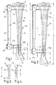
- a metallic nail 12 of constant length b which has been attached with its nail tip 14 to the bone end near the trunk and hammered into its marrow.
- the slightly angled proximal end 16 of the intramedullary nail 12 penetrates two transverse bores 18 at a distance i from one another, and an elongated hole or longitudinal slot 20 of a length t of, for example, 40 to 80 mm runs in the distal nail tip 14 in the central axis M of the intramedullary nail 12.
- 3, 4 further longitudinal bores 19 can be assigned to the longitudinal slot 20 axially or radially.
- the two proximal transverse bores 18 each receive a screw 22 which penetrates them and the tibia 10 and which, in the drawing on the left, sits outside the tibia 10 in a holding head 24 of a cylinder part 26.
- the screws 22, 23 are parallel to each other.
- the lower screws 23, 23p in the drawing pass through the tibia 10 and the longitudinal slot 20, the proximal screw 23p in FIG. 1 abutting the inside of the upper slot end.
- the nail tip 14 is used to guide the screws 23, 23p which move in the longitudinal slot 20 by increasing the effective length of the fixator 28; the distance e between the lower screw 23 and the distal end of the bone remains unchanged. Thanks to this mounting of the thread flanks of the screws 23, 23p in the intramedullary nail 12 and in the bone cortex 11 - the extension region of which is designated 11a in FIG. 2 - a uniform force distribution is produced.
- the screws 22, also referred to as Schanz screws are replaced by so-called locking screws (not shown) which hold the intramedullary nail 12 anchored in the bone.
- the distal nail area - nail tip 14 - is anchored by locking screws which penetrate the bores 19.
- the Schanz screws 23, 23p are also removed from the tibia 10.
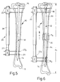
- extension nail 32 which in turn is variable in length. It is divided approximately into the longitudinal center, and the two nail parts 33, 34 thus created are partially hollow for receiving an axial piece 35 connecting them. This enables the telescopic extension of the extension nail 33 when the two nail parts 33, 34 are pulled apart.
- transverse bores 18, 18d are provided for the Schanz screws 22, 23, 23p both in the proximal nail part 33 and in the region of the distal nail tip 14 , ie the extension nail 32 remains fixed proximally and distally.
- the load is borne by the fixator 28 and the Schanz screws 22, 23, 23p in a rigid connection with the extension nail 32. If the intended maximum length a1 of the bone 10 is reached, the screws 22, 23, 23p are - as already described - replaced by locking screws.
- the distal nail part 34 is configured in its upper region as a sleeve 36, into which the rod-like end 38 of the proximal nail part 33 protrudes.
- This rod end 38 is provided with a longitudinal groove 49 in which a spring tongue 42 is fixed axially parallel is.
- Their outwardly curved tongue end 43 interacts with an inner toothed bar 46 molded into the sleeve 36; the lower tongue edge 44 can abut one of the upwardly directed shoulder or step surfaces 48 of the teeth 47 as a stop edge if the rod end 38 tries to slide against the stroke direction x.
- the pairing of step surface 48 / stop surface 44 thus acts as a reverse brake.
- the aforementioned Schanz screws are anchored in it and in the corticalis.
- the intramedullary nail 32 remains fixed proximally and distally.
- the load is borne by the fixator 28 and the Schanz screws in a rigid connection with the intramedullary nail 32, with no bending forces occurring on the fixator 28.
- the Schanz screw is replaced by locking screws, as already mentioned.
Landscapes
- Health & Medical Sciences (AREA)
- Orthopedic Medicine & Surgery (AREA)
- Surgery (AREA)
- Life Sciences & Earth Sciences (AREA)
- Heart & Thoracic Surgery (AREA)
- Nuclear Medicine, Radiotherapy & Molecular Imaging (AREA)
- Engineering & Computer Science (AREA)
- Biomedical Technology (AREA)
- Medical Informatics (AREA)
- Molecular Biology (AREA)
- Animal Behavior & Ethology (AREA)
- General Health & Medical Sciences (AREA)
- Public Health (AREA)
- Veterinary Medicine (AREA)
- Neurology (AREA)
- Surgical Instruments (AREA)
Applications Claiming Priority (2)
| Application Number | Priority Date | Filing Date | Title |
|---|---|---|---|
| DE4328015 | 1993-08-20 | ||
| DE19934328015 DE4328015A1 (de) | 1993-08-20 | 1993-08-20 | Vorrichtung zum Behandeln von Knochen |
Publications (1)
| Publication Number | Publication Date |
|---|---|
| EP0639352A1 true EP0639352A1 (fr) | 1995-02-22 |
Family
ID=6495623
Family Applications (1)
| Application Number | Title | Priority Date | Filing Date |
|---|---|---|---|
| EP94113002A Withdrawn EP0639352A1 (fr) | 1993-08-20 | 1994-08-19 | Dispositif pour traitement des os |
Country Status (2)
| Country | Link |
|---|---|
| EP (1) | EP0639352A1 (fr) |
| DE (1) | DE4328015A1 (fr) |
Cited By (20)
| Publication number | Priority date | Publication date | Assignee | Title |
|---|---|---|---|---|
| EP0696441A3 (fr) * | 1994-08-10 | 1996-04-03 | Howmedica Gmbh | Moyen de stabilisation d'os longs notamment pour l'ostéotomie |
| WO1997015176A3 (fr) * | 1995-10-21 | 1997-06-12 | Dietmar Pennig | Clou de cavite intramedullaire destine a l'elongation du femur |
| WO2002007620A3 (es) * | 2000-07-17 | 2002-04-25 | Davila Jorge P Flores | Dispositivo y metodo para la fijacion, compresion y distraccion osea |
| EP1350479A3 (fr) * | 2002-03-28 | 2004-10-06 | Depuy Orthopaedics, Inc. | Dispositif de fixation et appareil de centrage pour un clou intramedullaire |
| WO2013176632A1 (fr) * | 2012-05-23 | 2013-11-28 | Antolic Dr Vane | Dispositif latéral modulaire avec un clou intramédullaire pour le guidage d'un os durant son allongement |
| WO2014039205A1 (fr) * | 2012-09-04 | 2014-03-13 | Imds Corporation | Fixation externe |
| CN105476702A (zh) * | 2015-12-14 | 2016-04-13 | 重庆医科大学附属永川医院 | 一种用于肱骨大段骨缺损的骨搬运装置 |
| CN105476701A (zh) * | 2015-12-14 | 2016-04-13 | 重庆医科大学附属永川医院 | 一种用于股骨大段骨缺损的骨搬运装置 |
| JP2016528993A (ja) * | 2014-03-14 | 2016-09-23 | ライト メディカル テクノロジー インコーポレイテッドWright Medical Technology, Inc. | 整形外科圧縮/伸延装置 |
| CN106859757A (zh) * | 2015-12-14 | 2017-06-20 | 重庆医科大学附属永川医院 | 一种用于胫骨大段骨缺损的骨搬运装置 |
| US9770272B2 (en) | 2012-12-12 | 2017-09-26 | Wright Medical Technology, Inc. | Orthopedic compression/distraction device |
| WO2017203097A1 (fr) * | 2016-05-27 | 2017-11-30 | Synoste Oy | Dispositif d'ostéodistraction télescopique intracorporel, dispositif de production d'une force extracorporelle, procédé d'allongement des os et configuration d'allongement des os |
| US9924969B2 (en) | 2012-09-04 | 2018-03-27 | Zimmer, Inc. | External fixation |
| US9962187B2 (en) | 2014-08-11 | 2018-05-08 | Zimmer, Inc. | External fixation |
| CN105877830B (zh) * | 2015-12-14 | 2018-07-06 | 重庆医科大学附属永川医院 | 一种用于大段骨缺损的骨搬运装置 |
| CN110090050A (zh) * | 2019-05-24 | 2019-08-06 | 蚌埠医学院第一附属医院 | 一种治疗四肢骨折的牵引器 |
| EP3808293A1 (fr) * | 2019-10-17 | 2021-04-21 | Globus Medical, Inc. | Systèmes de stabilisation de l'humérus proximal et procédés associés |
| US11134988B2 (en) | 2015-06-17 | 2021-10-05 | Zimmer, Inc. | Ankle fixation system |
| US11202663B2 (en) | 2019-02-13 | 2021-12-21 | Globus Medical, Inc. | Proximal humeral stabilization systems and methods thereof |
| EP3820389A4 (fr) * | 2018-07-09 | 2022-03-23 | Tobb Ekonomi Ve Teknoloji Universitesi | Dispositif de fixation externe ayant un dispositif d'alignement |
Citations (3)
| Publication number | Priority date | Publication date | Assignee | Title |
|---|---|---|---|---|
| US2391537A (en) * | 1943-09-27 | 1945-12-25 | Anderson Roger | Ambulatory rotating reduction and fixation splint |
| DE2713837B1 (de) * | 1977-03-25 | 1978-03-02 | Westerhoff Erhard | Antriebsvorrichtung fuer ein Distraktionsgeraet |
| DE3921972A1 (de) * | 1989-07-04 | 1991-01-17 | Rainer Dr Baumgart | Marknagel |
-
1993
- 1993-08-20 DE DE19934328015 patent/DE4328015A1/de not_active Withdrawn
-
1994
- 1994-08-19 EP EP94113002A patent/EP0639352A1/fr not_active Withdrawn
Patent Citations (3)
| Publication number | Priority date | Publication date | Assignee | Title |
|---|---|---|---|---|
| US2391537A (en) * | 1943-09-27 | 1945-12-25 | Anderson Roger | Ambulatory rotating reduction and fixation splint |
| DE2713837B1 (de) * | 1977-03-25 | 1978-03-02 | Westerhoff Erhard | Antriebsvorrichtung fuer ein Distraktionsgeraet |
| DE3921972A1 (de) * | 1989-07-04 | 1991-01-17 | Rainer Dr Baumgart | Marknagel |
Cited By (36)
| Publication number | Priority date | Publication date | Assignee | Title |
|---|---|---|---|---|
| EP0696441A3 (fr) * | 1994-08-10 | 1996-04-03 | Howmedica Gmbh | Moyen de stabilisation d'os longs notamment pour l'ostéotomie |
| WO1997015176A3 (fr) * | 1995-10-21 | 1997-06-12 | Dietmar Pennig | Clou de cavite intramedullaire destine a l'elongation du femur |
| WO2002007620A3 (es) * | 2000-07-17 | 2002-04-25 | Davila Jorge P Flores | Dispositivo y metodo para la fijacion, compresion y distraccion osea |
| EP1350479A3 (fr) * | 2002-03-28 | 2004-10-06 | Depuy Orthopaedics, Inc. | Dispositif de fixation et appareil de centrage pour un clou intramedullaire |
| AU2003203216B2 (en) * | 2002-03-28 | 2008-10-09 | Depuy Orthopaedics, Inc. | Bone fastener targeting and compression/distraction device for an intramedullary nail and method of use |
| WO2013176632A1 (fr) * | 2012-05-23 | 2013-11-28 | Antolic Dr Vane | Dispositif latéral modulaire avec un clou intramédullaire pour le guidage d'un os durant son allongement |
| WO2014039205A1 (fr) * | 2012-09-04 | 2014-03-13 | Imds Corporation | Fixation externe |
| CN104619276A (zh) * | 2012-09-04 | 2015-05-13 | 捷迈有限公司 | 外固定器 |
| US9301782B2 (en) | 2012-09-04 | 2016-04-05 | Zimmer, Inc. | External fixation |
| US10433873B2 (en) | 2012-09-04 | 2019-10-08 | Zimmer, Inc. | External fixation |
| US10010348B2 (en) | 2012-09-04 | 2018-07-03 | Zimmer, Inc. | External fixation |
| CN104619276B (zh) * | 2012-09-04 | 2016-08-10 | 捷迈有限公司 | 外固定器 |
| US9924969B2 (en) | 2012-09-04 | 2018-03-27 | Zimmer, Inc. | External fixation |
| US10905469B2 (en) | 2012-09-04 | 2021-02-02 | Zimmer, Inc. | External fixation |
| US10631900B2 (en) | 2012-12-12 | 2020-04-28 | Wright Medical Technology, Inc. | Orthopedic compression/distraction device |
| US9770272B2 (en) | 2012-12-12 | 2017-09-26 | Wright Medical Technology, Inc. | Orthopedic compression/distraction device |
| JP2016528993A (ja) * | 2014-03-14 | 2016-09-23 | ライト メディカル テクノロジー インコーポレイテッドWright Medical Technology, Inc. | 整形外科圧縮/伸延装置 |
| US9962187B2 (en) | 2014-08-11 | 2018-05-08 | Zimmer, Inc. | External fixation |
| US10543019B2 (en) | 2014-08-11 | 2020-01-28 | Zimmer, Inc. | External fixation |
| US11134988B2 (en) | 2015-06-17 | 2021-10-05 | Zimmer, Inc. | Ankle fixation system |
| CN105476702A (zh) * | 2015-12-14 | 2016-04-13 | 重庆医科大学附属永川医院 | 一种用于肱骨大段骨缺损的骨搬运装置 |
| CN105877830B (zh) * | 2015-12-14 | 2018-07-06 | 重庆医科大学附属永川医院 | 一种用于大段骨缺损的骨搬运装置 |
| CN106859757B (zh) * | 2015-12-14 | 2018-07-06 | 重庆医科大学附属永川医院 | 一种用于胫骨大段骨缺损的骨搬运装置 |
| CN106859757A (zh) * | 2015-12-14 | 2017-06-20 | 重庆医科大学附属永川医院 | 一种用于胫骨大段骨缺损的骨搬运装置 |
| CN105476701A (zh) * | 2015-12-14 | 2016-04-13 | 重庆医科大学附属永川医院 | 一种用于股骨大段骨缺损的骨搬运装置 |
| CN109195539A (zh) * | 2016-05-27 | 2019-01-11 | 希努斯帝有限公司 | 体内伸缩式骨牵引装置、体外力产生装置、骨延长方法和骨延长布置 |
| WO2017203097A1 (fr) * | 2016-05-27 | 2017-11-30 | Synoste Oy | Dispositif d'ostéodistraction télescopique intracorporel, dispositif de production d'une force extracorporelle, procédé d'allongement des os et configuration d'allongement des os |
| CN109195539B (zh) * | 2016-05-27 | 2022-03-01 | 希努斯帝有限公司 | 体内伸缩式骨牵引装置、体外力产生装置、骨延长方法和骨延长布置 |
| US11160588B2 (en) | 2016-05-27 | 2021-11-02 | Bala Sundararajan | System for stabilizing or lengthening bone |
| EP3820389A4 (fr) * | 2018-07-09 | 2022-03-23 | Tobb Ekonomi Ve Teknoloji Universitesi | Dispositif de fixation externe ayant un dispositif d'alignement |
| US11202663B2 (en) | 2019-02-13 | 2021-12-21 | Globus Medical, Inc. | Proximal humeral stabilization systems and methods thereof |
| US11259848B2 (en) | 2019-02-13 | 2022-03-01 | Globus Medical, Inc. | Proximal humeral stabilization systems and methods thereof |
| US12076063B2 (en) | 2019-02-13 | 2024-09-03 | Globus Medical, Inc. | Proximal humeral stabilization systems and methods thereof |
| US12185993B2 (en) | 2019-02-13 | 2025-01-07 | Globus Medical, Inc. | Proximal humeral stabilization systems and methods thereof |
| CN110090050A (zh) * | 2019-05-24 | 2019-08-06 | 蚌埠医学院第一附属医院 | 一种治疗四肢骨折的牵引器 |
| EP3808293A1 (fr) * | 2019-10-17 | 2021-04-21 | Globus Medical, Inc. | Systèmes de stabilisation de l'humérus proximal et procédés associés |
Also Published As
| Publication number | Publication date |
|---|---|
| DE4328015A1 (de) | 1995-02-23 |
Similar Documents
| Publication | Publication Date | Title |
|---|---|---|
| EP0639352A1 (fr) | Dispositif pour traitement des os | |
| DE60014042T2 (de) | Axialer äusserer Fixateur | |
| EP1761182B1 (fr) | Clou chirurgical | |
| DE3855014T2 (de) | Intramedulläre, intertrochanterische Bruckfixierungsvorrichtung sowie Montagevorrichtung | |
| DE69717741T2 (de) | Suprakondylärer Knochennagel | |
| DE69115302T2 (de) | Intramedulläre Hüftschraube | |
| DE3541597C2 (fr) | ||
| EP2263584B1 (fr) | Clou intramédullaire avec vis de blocage | |
| EP2347724B1 (fr) | Dispositif de serrage pour éléments chirurgicaux | |
| EP1830727B1 (fr) | Clou medullaire | |
| EP1415604B1 (fr) | Système de fixation d'os | |
| EP0736286A2 (fr) | Instrument auxiliaire pour ostéosynthèse permettant de traiter des fractures subtrochantériennes et pertrochantériennes, ainsi que des fractures du col du fémur | |
| DE9115200U1 (de) | Verriegelungsnagel für die Versorgung von Frakturen der Röhrenknochen | |
| WO2000067652A2 (fr) | Implant pour le traitement operatoire de fractures du col du femur ou similaires | |
| EP2468216B1 (fr) | Prothèse pouvant être implantée destinée à remplacer une articulation de hanche ou de genou humains et des sections d'os limitrophes | |
| EP1648321A1 (fr) | Clou chirurgical | |
| EP0715832B1 (fr) | Broche intramédullaire pour compression de la hanche | |
| DE2246274A1 (de) | Vorrichtung zur behandlung von gebrochenen roehrenknochen durch axiale druckosteosynthese | |
| EP1455662B1 (fr) | Dispositif de visee destine a une broche a fracture | |
| EP1572018B1 (fr) | Clou permettant de reparer des fractures osseuses | |
| DE2542263A1 (de) | Marknagel fuer die osteosynthese bei frakturen von roehrenknochen | |
| DE102007029090A1 (de) | Vorrichtung zur Osteosynthese gelenknaher Knochenfrakturen | |
| DE19731879C2 (de) | Intramedulläres Schienungssystem für Röhrenknochen | |
| WO2002080790A1 (fr) | Broche a usage chirurgical | |
| EP1491155A1 (fr) | Instrument medical à tige coulissante, en particulier poinçonneuse à tissu |
Legal Events
| Date | Code | Title | Description |
|---|---|---|---|
| PUAI | Public reference made under article 153(3) epc to a published international application that has entered the european phase |
Free format text: ORIGINAL CODE: 0009012 |
|
| AK | Designated contracting states |
Kind code of ref document: A1 Designated state(s): AT BE CH DE DK ES FR GB GR IE IT LI LU MC NL PT SE |
|
| RAX | Requested extension states of the european patent have changed |
Free format text: SI |
|
| 17P | Request for examination filed |
Effective date: 19950310 |
|
| STAA | Information on the status of an ep patent application or granted ep patent |
Free format text: STATUS: THE APPLICATION IS DEEMED TO BE WITHDRAWN |
|
| 18D | Application deemed to be withdrawn |
Effective date: 19990302 |
|
| R18D | Application deemed to be withdrawn (corrected) |
Effective date: 19990301 |