EP0639473A2 - Ressort pneumatique pour supporter la caisse d'un véhicule - Google Patents
Ressort pneumatique pour supporter la caisse d'un véhicule Download PDFInfo
- Publication number
- EP0639473A2 EP0639473A2 EP94112824A EP94112824A EP0639473A2 EP 0639473 A2 EP0639473 A2 EP 0639473A2 EP 94112824 A EP94112824 A EP 94112824A EP 94112824 A EP94112824 A EP 94112824A EP 0639473 A2 EP0639473 A2 EP 0639473A2
- Authority
- EP
- European Patent Office
- Prior art keywords
- air spring
- bellows
- attached
- vehicle
- vehicle component
- Prior art date
- Legal status (The legal status is an assumption and is not a legal conclusion. Google has not performed a legal analysis and makes no representation as to the accuracy of the status listed.)
- Withdrawn
Links
Images
Classifications
-
- B—PERFORMING OPERATIONS; TRANSPORTING
- B60—VEHICLES IN GENERAL
- B60G—VEHICLE SUSPENSION ARRANGEMENTS
- B60G15/00—Resilient suspensions characterised by arrangement, location or type of combined spring and vibration damper, e.g. telescopic type
- B60G15/08—Resilient suspensions characterised by arrangement, location or type of combined spring and vibration damper, e.g. telescopic type having fluid spring
- B60G15/10—Resilient suspensions characterised by arrangement, location or type of combined spring and vibration damper, e.g. telescopic type having fluid spring and mechanical damper or dynamic damper
-
- F—MECHANICAL ENGINEERING; LIGHTING; HEATING; WEAPONS; BLASTING
- F16—ENGINEERING ELEMENTS AND UNITS; GENERAL MEASURES FOR PRODUCING AND MAINTAINING EFFECTIVE FUNCTIONING OF MACHINES OR INSTALLATIONS; THERMAL INSULATION IN GENERAL
- F16F—SPRINGS; SHOCK-ABSORBERS; MEANS FOR DAMPING VIBRATION
- F16F7/00—Vibration-dampers; Shock-absorbers
- F16F7/10—Vibration-dampers; Shock-absorbers using inertia effect
- F16F7/104—Vibration-dampers; Shock-absorbers using inertia effect the inertia member being resiliently mounted
- F16F7/108—Vibration-dampers; Shock-absorbers using inertia effect the inertia member being resiliently mounted on plastics springs
-
- F—MECHANICAL ENGINEERING; LIGHTING; HEATING; WEAPONS; BLASTING
- F16—ENGINEERING ELEMENTS AND UNITS; GENERAL MEASURES FOR PRODUCING AND MAINTAINING EFFECTIVE FUNCTIONING OF MACHINES OR INSTALLATIONS; THERMAL INSULATION IN GENERAL
- F16F—SPRINGS; SHOCK-ABSORBERS; MEANS FOR DAMPING VIBRATION
- F16F9/00—Springs, vibration-dampers, shock-absorbers, or similarly-constructed movement-dampers using a fluid or the equivalent as damping medium
- F16F9/02—Springs, vibration-dampers, shock-absorbers, or similarly-constructed movement-dampers using a fluid or the equivalent as damping medium using gas only or vacuum
- F16F9/04—Springs, vibration-dampers, shock-absorbers, or similarly-constructed movement-dampers using a fluid or the equivalent as damping medium using gas only or vacuum in a chamber with a flexible wall
- F16F9/05—Springs, vibration-dampers, shock-absorbers, or similarly-constructed movement-dampers using a fluid or the equivalent as damping medium using gas only or vacuum in a chamber with a flexible wall the flexible wall being of the rolling diaphragm type
-
- B—PERFORMING OPERATIONS; TRANSPORTING
- B60—VEHICLES IN GENERAL
- B60G—VEHICLE SUSPENSION ARRANGEMENTS
- B60G2202/00—Indexing codes relating to the type of spring, damper or actuator
- B60G2202/10—Type of spring
- B60G2202/15—Fluid spring
- B60G2202/152—Pneumatic spring
-
- B—PERFORMING OPERATIONS; TRANSPORTING
- B60—VEHICLES IN GENERAL
- B60G—VEHICLE SUSPENSION ARRANGEMENTS
- B60G2202/00—Indexing codes relating to the type of spring, damper or actuator
- B60G2202/20—Type of damper
- B60G2202/25—Dynamic damper
Definitions
- the invention relates to an air spring for supporting a vehicle body on another vibrating vehicle component according to the preamble of patent claim 1.
- Air springs with elastomeric air bellows are known in a variety of embodiments and have e.g. Proven to a large extent as vehicle suspensions, in particular for cushioning vehicle bodies against the wheel axles of trucks and buses or driver's cab against vehicle frames.
- the air bellows are tightly attached at their ends to a connecting part, which are usually made of metal or plastic.
- the bellows is attached to the vehicle frame on the one hand and to the vehicle axle on the other hand via the connecting parts.
- the vibrations on the axle are initiated, for example, by the height of a wheel or uneven road surfaces. If the vibrations are in the natural frequency of the axle, this has negative effects on the driving comfort and driving safety of the vehicle. It was also found that the vehicle body supported by the air suspension by the greater vibrational forces can be excited to mechanical oscillations or vibrations. These are noticeable in the vehicle body. Structure-borne noise can also be emitted via this excitation.
- the invention has for its object to provide an air spring of the type described, by the structure of vibrations of the vehicle component are reduced in the resonance range.
- connection part attached to the vehicle has an elastically connected vibration damper mass.
- connection part attached to the vehicle component has an integrated vibration damper which reduces the vibrations in the resonance region of the vehicle component.
- the absorber mass is supported by an elastomer spring element that is specially matched to the air spring connection part in terms of rigidity and damping to the natural frequency of the vehicle component.
- An advantageous embodiment of the invention is characterized in claim 2.
- the bellows are tightly attached to a rolling piston at at least one end.
- This rolling piston serves as a connector and is attached to the vehicle axle in vehicles.
- the rolling piston moves within the rolling bellows due to the compression and rebound, which turns inside out and forms a rolling fold that rolls depending on the compression or rebound movement over the outer surface of the rolling piston.
- a further advantageous embodiment of the invention is characterized in claim 3.
- the circular vibration damper mass results in a rotationally symmetrical structure of the rolling piston which is easy to manufacture.
- the elastomer body of the vibration damper can be acted upon on one side with variable pressure. This makes the stiffness of the damper bearing adjustable.
- the vibration damper can be detuned by applying different pressures.
- the vibration damper can thus be adapted to different resonance frequencies of a vehicle component.
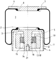
- the air spring shown has an elastomeric bellows 1, which sits with its lower bellows opening, which is delimited by a conical sealing bead 2, on a conical sealing seat 3 of a rolling piston 4.
- the conical sealing seat 3 is smaller in diameter than the rolling piston 4 and lies on its upper end plate 5.
- the bellows 1 With its upper sealing bead 7, the bellows 1 is arranged on a conical sealing seat 8 of a connecting part designed as a connecting plate 9.
- the connecting plate 9 is fastened to a vehicle frame via elements not shown here, while the rolling piston 4 is attached to a part of the vehicle axle.
- the bellows 1 is shown in the operating state of the air spring.
- a roll fold 11 of the roll bellows 1 is formed, which rolls over the outer surface of the piston wall 12 of the roll-off piston when it springs in and out.
- the rolling piston 4 has a central, downwardly tapering support shoulder 14, which is connected to the piston wall 12 via the horizontal end plate 5 of the rolling piston 4 and is surrounded by the concentrically arranged piston wall 12.
- the support lug 14 has a snap ring 15 on which a conical metal sleeve 16 rests.
- the outer circumference of the conical metal sleeve 16 is vulcanized together in a hub shape with an intermediate ring 17 made of rubber.
- the outer circumference of the intermediate ring 17 carries a vulcanized, annular absorber mass 18, which is positively supported by a step 19 on the upper end face of the intermediate ring 17.
- the bottom of the rolling piston 4 is provided with a threaded bore 21 through which the rolling piston is fixed to a lower vehicle component, e.g. a vehicle axle can be connected.
- the vehicle axle When driving over uneven ground, the vehicle axle is excited to vibrate in the resonance area of the vehicle axle via the tires.
- the rolling piston is firmly connected to the axle, so that the vibration absorber arranged in the rolling piston is also excited.
- the vibration damper is designed for axis resonance. As a result, an oscillation in phase opposition to the axis vibration is achieved.
- the vibration damper counteracts and reduces the axis vibrations. As a result, less vibration energy is transferred to the vehicle frame via the air spring, which leads to a reduction in the disruptive effects of the axle vibrations.
Landscapes
- Engineering & Computer Science (AREA)
- General Engineering & Computer Science (AREA)
- Mechanical Engineering (AREA)
- Vehicle Body Suspensions (AREA)
- Fluid-Damping Devices (AREA)
- Vibration Prevention Devices (AREA)
Applications Claiming Priority (3)
| Application Number | Priority Date | Filing Date | Title |
|---|---|---|---|
| DE4327883A DE4327883C2 (de) | 1993-08-19 | 1993-08-19 | Luftfeder zur Abstützung eines Fahrzeugkörpers |
| DE4327883 | 1993-08-19 | ||
| US08/356,522 US5509641A (en) | 1993-08-19 | 1994-12-15 | Air spring which includes a vibration absorbing mass |
Publications (2)
| Publication Number | Publication Date |
|---|---|
| EP0639473A2 true EP0639473A2 (fr) | 1995-02-22 |
| EP0639473A3 EP0639473A3 (fr) | 1995-07-26 |
Family
ID=25928764
Family Applications (1)
| Application Number | Title | Priority Date | Filing Date |
|---|---|---|---|
| EP94112824A Withdrawn EP0639473A3 (fr) | 1993-08-19 | 1994-08-17 | Ressort pneumatique pour supporter la caisse d'un véhicule. |
Country Status (3)
| Country | Link |
|---|---|
| US (1) | US5509641A (fr) |
| EP (1) | EP0639473A3 (fr) |
| DE (1) | DE4327883C2 (fr) |
Cited By (1)
| Publication number | Priority date | Publication date | Assignee | Title |
|---|---|---|---|---|
| US8517357B2 (en) | 2009-06-19 | 2013-08-27 | Firestone Industrial Products Company, Llc | Gas spring and damper assembly |
Families Citing this family (11)
| Publication number | Priority date | Publication date | Assignee | Title |
|---|---|---|---|---|
| WO1996012121A1 (fr) * | 1994-10-12 | 1996-04-25 | Lord Corporation | Procedes et dispositifs actifs comprenant des amortisseurs de vibrations actifs (ava) |
| DE19639556A1 (de) * | 1996-09-26 | 1998-04-09 | Mannesmann Boge Gmbh | Vorrichtung zur Tilgung von Schwingungen |
| DE20104043U1 (de) * | 2001-03-08 | 2001-07-12 | TRW Automotive Safety Systems GmbH & Co. KG, 63743 Aschaffenburg | Vorrichtung zur Dämpfung von Schwingungen in einem Lenkrad |
| US8186657B2 (en) | 2007-09-06 | 2012-05-29 | Firestone Industrial Products Company, Llc | Air spring modular piston |
| KR101218834B1 (ko) | 2010-09-29 | 2013-01-07 | 주식회사 만도 | 차체 거동 감응형 에어 스프링 |
| DE102011085323A1 (de) * | 2011-02-11 | 2012-08-16 | Continental Teves Ag & Co. Ohg | Kolben für eine Luftfeder |
| EP2780607B1 (fr) * | 2011-11-15 | 2019-06-26 | Continental Teves AG & Co. OHG | Ressort pneumatique |
| DE102012103358A1 (de) * | 2012-04-18 | 2013-10-24 | Contitech Luftfedersysteme Gmbh | Abrollkolben für einen Luftfederrollbalg |
| GB201405647D0 (en) * | 2014-03-28 | 2014-05-14 | Carbon Air Ltd | Transfer method and apparatus |
| DE102015224849A1 (de) * | 2015-12-10 | 2017-06-29 | Volkswagen Aktiengesellschaft | Dämpfervorrichtung sowie Verfahren zur Beeinflussung eines Schwingungsverhaltens einer Dämpfervorrichtung |
| JP6824715B2 (ja) * | 2016-12-07 | 2021-02-03 | Toyo Tire株式会社 | ダイナミックダンパ |
Family Cites Families (18)
| Publication number | Priority date | Publication date | Assignee | Title |
|---|---|---|---|---|
| US2149863A (en) * | 1937-07-06 | 1939-03-07 | Gen Motors Corp | Harmonic balancer for vehicle road wheels |
| US2865651A (en) * | 1954-12-30 | 1958-12-23 | Gen Motors Corp | Combined wheel hop damper and air spring suspension |
| DE1003608B (de) * | 1956-08-04 | 1957-02-28 | Metallgummi G M B H | Luftfeder, insbesondere fuer Kraftfahrzeuge |
| DE1285792B (de) * | 1966-11-07 | 1968-12-19 | Continental Gummi Werke Ag | Luftfeder mit einem verformbare Wandungen und verstaerkte Wuelste aufweisenden Balg |
| FR2256849A1 (en) * | 1974-01-08 | 1975-08-01 | Germain Roger | Shock absorber for vehicle wheel - has rolling membrane and buffer between outer casing and inner piston housing |
| DE3246599A1 (de) * | 1982-12-16 | 1984-06-20 | Continental Gummi-Werke Ag, 3000 Hannover | Rollbalg fuer fahrzeug-luftfederungen |
| DE3641623A1 (de) * | 1985-12-21 | 1987-06-25 | Gold Henning | Pneumatische feder-daempfer-einheit |
| JPS62167943A (ja) * | 1986-01-21 | 1987-07-24 | Bridgestone Corp | 空気ばね |
| JPS6397413A (ja) * | 1986-10-13 | 1988-04-28 | Mazda Motor Corp | 自動車のサスペンシヨン装置 |
| WO1988005506A1 (fr) * | 1987-01-16 | 1988-07-28 | Topexpress Limited | Regulation active de vibrations |
| SU1458629A1 (ru) * | 1987-05-21 | 1989-02-15 | Vnii Vagonostroenia | Пневматический упругий элемент |
| SU1521953A1 (ru) * | 1987-05-27 | 1989-11-15 | Rakhmanov Nikolaj N | Упруга подвеска |
| JPH0268212A (ja) * | 1988-09-03 | 1990-03-07 | Mazda Motor Corp | 車両のサスペンション装置 |
| DE4127616C1 (fr) * | 1991-08-21 | 1992-11-26 | Mercedes-Benz Aktiengesellschaft, 7000 Stuttgart, De | |
| DE4129797C2 (de) * | 1991-09-09 | 1996-12-19 | Porsche Ag | Schwingungstilger |
| JPH05196083A (ja) * | 1992-01-21 | 1993-08-06 | Bridgestone Corp | 空気ばね |
| DE4209610C1 (fr) * | 1992-03-25 | 1993-03-11 | Fa. Carl Freudenberg, 6940 Weinheim, De | |
| JPH0617867A (ja) * | 1992-06-29 | 1994-01-25 | Bridgestone Corp | 高さ調整機構付き空気ばね |
-
1993
- 1993-08-19 DE DE4327883A patent/DE4327883C2/de not_active Expired - Fee Related
-
1994
- 1994-08-17 EP EP94112824A patent/EP0639473A3/fr not_active Withdrawn
- 1994-12-15 US US08/356,522 patent/US5509641A/en not_active Expired - Fee Related
Cited By (1)
| Publication number | Priority date | Publication date | Assignee | Title |
|---|---|---|---|---|
| US8517357B2 (en) | 2009-06-19 | 2013-08-27 | Firestone Industrial Products Company, Llc | Gas spring and damper assembly |
Also Published As
| Publication number | Publication date |
|---|---|
| DE4327883A1 (de) | 1995-02-23 |
| DE4327883C2 (de) | 1995-06-08 |
| EP0639473A3 (fr) | 1995-07-26 |
| US5509641A (en) | 1996-04-23 |
Similar Documents
| Publication | Publication Date | Title |
|---|---|---|
| DE3720729C2 (de) | Feder-Dämpfer-Einheit | |
| DE3878658T2 (de) | Luftfederaufhaengung mit zweiseitiger isolierung. | |
| EP0839676B1 (fr) | Ressort pneumatique à soufflet roulant | |
| DE10229287B4 (de) | Dämpferlager mit konturierter Stirnfläche für Stoßdämpfer in Kraftfahrzeugen | |
| EP2605923B1 (fr) | Jambe de force a ressort pneumatique avec le montage souple du piston | |
| EP1144210A2 (fr) | Systeme d'amortisseur pneumatique | |
| EP1693233B1 (fr) | Jambe de ressort pneumatique avec amortisseur positionné centralement | |
| EP0944486A1 (fr) | Systeme de suspension pneumatique | |
| DE2517799B2 (de) | Aufhängung des Triebwerkes am Fahrgestell eines Kraftfahrzeuges | |
| DE4327883C2 (de) | Luftfeder zur Abstützung eines Fahrzeugkörpers | |
| EP3510303A1 (fr) | Ensemble ressort pneumatique à guidage externe divisé | |
| DE102013219912A1 (de) | Endelement und Gasfederanordnung, welche dasselbe aufweist | |
| DE4008187A1 (de) | Abrollkolben fuer den rollbalg einer rollbalg-luftfeder | |
| DE102011001495B4 (de) | Aktives Luftfeder-Dämpfer-Modul | |
| DE69606903T3 (de) | Luftgefederte Fahrzeugaufhängungsvorrichtung, vom Eingangskrafttrennungstyp, miteiner Luftkammer in der Nähe des unteren Dämpferendes | |
| DE3204816A1 (de) | Oberes verankerungssystem fuer ein federbein einer mcpherson-aufhaengung | |
| WO2002081943A2 (fr) | Systeme de support modulaire | |
| EP1837548B1 (fr) | Unité d'amortissement et de ressort à air dotée d'un pli roulé détendu | |
| EP1402195B1 (fr) | Suspension pneumatique | |
| DE102007029490B4 (de) | Kolben-Zylinder-Aggregat | |
| DE102017216052A1 (de) | Luftfederbein mit einem Luftfederdeckel mit Bajonettverschluss | |
| DE4010858C2 (fr) | ||
| DE102016216911A1 (de) | Luftfedereinheit mit großvolumigem Luftfederdeckel | |
| DE69617624T2 (de) | Anordnung für eine elastische aufhängung zwischen fahrerhaus und fahrzeugrahmen | |
| EP3372864B1 (fr) | Ressort à air comprenant un soufflet |
Legal Events
| Date | Code | Title | Description |
|---|---|---|---|
| PUAI | Public reference made under article 153(3) epc to a published international application that has entered the european phase |
Free format text: ORIGINAL CODE: 0009012 |
|
| AK | Designated contracting states |
Kind code of ref document: A2 Designated state(s): AT BE CH DE ES FR GB IT LI NL SE |
|
| PUAL | Search report despatched |
Free format text: ORIGINAL CODE: 0009013 |
|
| AK | Designated contracting states |
Kind code of ref document: A3 Designated state(s): AT BE CH DE ES FR GB IT LI NL SE |
|
| 17P | Request for examination filed |
Effective date: 19950824 |
|
| 17Q | First examination report despatched |
Effective date: 19951011 |
|
| STAA | Information on the status of an ep patent application or granted ep patent |
Free format text: STATUS: THE APPLICATION IS DEEMED TO BE WITHDRAWN |
|
| 18D | Application deemed to be withdrawn |
Effective date: 19960423 |