EP0639477A1 - Ensemble d'actionnement, en particulier pour sièges de véhicules - Google Patents
Ensemble d'actionnement, en particulier pour sièges de véhicules Download PDFInfo
- Publication number
- EP0639477A1 EP0639477A1 EP94112205A EP94112205A EP0639477A1 EP 0639477 A1 EP0639477 A1 EP 0639477A1 EP 94112205 A EP94112205 A EP 94112205A EP 94112205 A EP94112205 A EP 94112205A EP 0639477 A1 EP0639477 A1 EP 0639477A1
- Authority
- EP
- European Patent Office
- Prior art keywords
- assembly
- guide
- slide
- fitted
- relation
- Prior art date
- Legal status (The legal status is an assumption and is not a legal conclusion. Google has not performed a legal analysis and makes no representation as to the accuracy of the status listed.)
- Granted
Links
- 230000003213 activating effect Effects 0.000 claims 4
- 230000000712 assembly Effects 0.000 description 9
- 238000000429 assembly Methods 0.000 description 9
- 238000006073 displacement reaction Methods 0.000 description 5
- 239000011435 rock Substances 0.000 description 2
- 229910000831 Steel Inorganic materials 0.000 description 1
- 239000004411 aluminium Substances 0.000 description 1
- 229910052782 aluminium Inorganic materials 0.000 description 1
- XAGFODPZIPBFFR-UHFFFAOYSA-N aluminium Chemical compound [Al] XAGFODPZIPBFFR-UHFFFAOYSA-N 0.000 description 1
- 230000001771 impaired effect Effects 0.000 description 1
- 239000000463 material Substances 0.000 description 1
- 229910052751 metal Inorganic materials 0.000 description 1
- 239000002184 metal Substances 0.000 description 1
- 230000010355 oscillation Effects 0.000 description 1
- 239000010959 steel Substances 0.000 description 1
Images

Classifications
-
- B—PERFORMING OPERATIONS; TRANSPORTING
- B60—VEHICLES IN GENERAL
- B60N—SEATS SPECIALLY ADAPTED FOR VEHICLES; VEHICLE PASSENGER ACCOMMODATION NOT OTHERWISE PROVIDED FOR
- B60N2/00—Seats specially adapted for vehicles; Arrangement or mounting of seats in vehicles
- B60N2/02—Seats specially adapted for vehicles; Arrangement or mounting of seats in vehicles the seat or part thereof being movable, e.g. adjustable
- B60N2/04—Seats specially adapted for vehicles; Arrangement or mounting of seats in vehicles the seat or part thereof being movable, e.g. adjustable the whole seat being movable
- B60N2/06—Seats specially adapted for vehicles; Arrangement or mounting of seats in vehicles the seat or part thereof being movable, e.g. adjustable the whole seat being movable slidable
- B60N2/067—Seats specially adapted for vehicles; Arrangement or mounting of seats in vehicles the seat or part thereof being movable, e.g. adjustable the whole seat being movable slidable by linear actuators, e.g. linear screw mechanisms
-
- B—PERFORMING OPERATIONS; TRANSPORTING
- B60—VEHICLES IN GENERAL
- B60N—SEATS SPECIALLY ADAPTED FOR VEHICLES; VEHICLE PASSENGER ACCOMMODATION NOT OTHERWISE PROVIDED FOR
- B60N2/00—Seats specially adapted for vehicles; Arrangement or mounting of seats in vehicles
- B60N2/02—Seats specially adapted for vehicles; Arrangement or mounting of seats in vehicles the seat or part thereof being movable, e.g. adjustable
- B60N2/0224—Non-manual adjustments, e.g. with electrical operation
- B60N2/02246—Electric motors therefor
- B60N2/02258—Electric motors therefor characterised by the mounting of the electric motor for adjusting the seat
-
- B—PERFORMING OPERATIONS; TRANSPORTING
- B60—VEHICLES IN GENERAL
- B60N—SEATS SPECIALLY ADAPTED FOR VEHICLES; VEHICLE PASSENGER ACCOMMODATION NOT OTHERWISE PROVIDED FOR
- B60N2/00—Seats specially adapted for vehicles; Arrangement or mounting of seats in vehicles
- B60N2/02—Seats specially adapted for vehicles; Arrangement or mounting of seats in vehicles the seat or part thereof being movable, e.g. adjustable
- B60N2/04—Seats specially adapted for vehicles; Arrangement or mounting of seats in vehicles the seat or part thereof being movable, e.g. adjustable the whole seat being movable
- B60N2/16—Seats specially adapted for vehicles; Arrangement or mounting of seats in vehicles the seat or part thereof being movable, e.g. adjustable the whole seat being movable height-adjustable
- B60N2/1605—Seats specially adapted for vehicles; Arrangement or mounting of seats in vehicles the seat or part thereof being movable, e.g. adjustable the whole seat being movable height-adjustable characterised by the cinematic
- B60N2/1625—Combination of rods and slides
-
- B—PERFORMING OPERATIONS; TRANSPORTING
- B60—VEHICLES IN GENERAL
- B60N—SEATS SPECIALLY ADAPTED FOR VEHICLES; VEHICLE PASSENGER ACCOMMODATION NOT OTHERWISE PROVIDED FOR
- B60N2/00—Seats specially adapted for vehicles; Arrangement or mounting of seats in vehicles
- B60N2/02—Seats specially adapted for vehicles; Arrangement or mounting of seats in vehicles the seat or part thereof being movable, e.g. adjustable
- B60N2/04—Seats specially adapted for vehicles; Arrangement or mounting of seats in vehicles the seat or part thereof being movable, e.g. adjustable the whole seat being movable
- B60N2/16—Seats specially adapted for vehicles; Arrangement or mounting of seats in vehicles the seat or part thereof being movable, e.g. adjustable the whole seat being movable height-adjustable
- B60N2/1635—Seats specially adapted for vehicles; Arrangement or mounting of seats in vehicles the seat or part thereof being movable, e.g. adjustable the whole seat being movable height-adjustable characterised by the drive mechanism
-
- B—PERFORMING OPERATIONS; TRANSPORTING
- B60—VEHICLES IN GENERAL
- B60N—SEATS SPECIALLY ADAPTED FOR VEHICLES; VEHICLE PASSENGER ACCOMMODATION NOT OTHERWISE PROVIDED FOR
- B60N2/00—Seats specially adapted for vehicles; Arrangement or mounting of seats in vehicles
- B60N2/02—Seats specially adapted for vehicles; Arrangement or mounting of seats in vehicles the seat or part thereof being movable, e.g. adjustable
- B60N2/04—Seats specially adapted for vehicles; Arrangement or mounting of seats in vehicles the seat or part thereof being movable, e.g. adjustable the whole seat being movable
- B60N2/16—Seats specially adapted for vehicles; Arrangement or mounting of seats in vehicles the seat or part thereof being movable, e.g. adjustable the whole seat being movable height-adjustable
- B60N2/18—Seats specially adapted for vehicles; Arrangement or mounting of seats in vehicles the seat or part thereof being movable, e.g. adjustable the whole seat being movable height-adjustable the front or the rear portion of the seat being adjustable, e.g. independently of each other
- B60N2/1807—Seats specially adapted for vehicles; Arrangement or mounting of seats in vehicles the seat or part thereof being movable, e.g. adjustable the whole seat being movable height-adjustable the front or the rear portion of the seat being adjustable, e.g. independently of each other characterised by the cinematic
- B60N2/1821—Combination of Rods and slides
-
- B—PERFORMING OPERATIONS; TRANSPORTING
- B60—VEHICLES IN GENERAL
- B60N—SEATS SPECIALLY ADAPTED FOR VEHICLES; VEHICLE PASSENGER ACCOMMODATION NOT OTHERWISE PROVIDED FOR
- B60N2/00—Seats specially adapted for vehicles; Arrangement or mounting of seats in vehicles
- B60N2/02—Seats specially adapted for vehicles; Arrangement or mounting of seats in vehicles the seat or part thereof being movable, e.g. adjustable
- B60N2/04—Seats specially adapted for vehicles; Arrangement or mounting of seats in vehicles the seat or part thereof being movable, e.g. adjustable the whole seat being movable
- B60N2/16—Seats specially adapted for vehicles; Arrangement or mounting of seats in vehicles the seat or part thereof being movable, e.g. adjustable the whole seat being movable height-adjustable
- B60N2/18—Seats specially adapted for vehicles; Arrangement or mounting of seats in vehicles the seat or part thereof being movable, e.g. adjustable the whole seat being movable height-adjustable the front or the rear portion of the seat being adjustable, e.g. independently of each other
- B60N2/1807—Seats specially adapted for vehicles; Arrangement or mounting of seats in vehicles the seat or part thereof being movable, e.g. adjustable the whole seat being movable height-adjustable the front or the rear portion of the seat being adjustable, e.g. independently of each other characterised by the cinematic
- B60N2/1839—Seats specially adapted for vehicles; Arrangement or mounting of seats in vehicles the seat or part thereof being movable, e.g. adjustable the whole seat being movable height-adjustable the front or the rear portion of the seat being adjustable, e.g. independently of each other characterised by the cinematic pivoting about an axis located in an intermediate position
Definitions
- the present invention relates to an actuator assembly, particularly for vehicle seats.
- actuator assemblies For adjusting the position of a vehicle seat in relation to the floor, actuator assemblies interposed between the seat portion of the seat and the vehicle floor are used for adjusting the seat horizontally and vertically.
- the seat is normally adjusted horizontally by means of a device comprising a pair of first guides fitted to the floor, and a pair of first slides moved along the first guides by a powered rack and pinion drive.
- the powered drive comprises a pair of racks, each connected integral with a respective first guide, and a pair of pinions, each meshing with a respective rack and fitted to a respective end portion of a powered shaft connected to the first slides transversely in relation to the first guides.
- known actuator assemblies comprise a ramp device in turn comprising a pair of second slides supporting the seat frame, defined at the bottom by respective inclined edges, and each fitted in sliding manner to the inclined top edge of a respective first slide.
- Relative movement of the first and second slides is normally achieved by means of two screw-nut screw devices, each fitted to a respective second slide and operated by a respective electric motor.
- ramp devices of the aforementioned type are less than satisfactory from the operating standpoint, by virtue of vertical adjustment of the seat also resulting automatically in an undesired change in its longitudinal position.
- known actuator assemblies provide for an extremely limited amount of vertical adjustment; and, by virtue of normally being fitted in projecting manner, the screws of the screw-nut screw devices may oscillate during actual adjustment, thus resulting in jamming and impaired operation of the assembly as a whole.
- an actuator assembly particularly for vehicle seats, interposed between the seat and a supporting body, and comprising guide means fitted to said supporting body, for longitudinally guiding the seat, and control means for vertically adjusting the position of the seat in relation to the guide means; characterized in that it comprises two side members, each comprising a bottom portion fitted in sliding manner to said guide means, and a top portion fitted to the seat; said control means comprising, for each said side member, a first guide-slide assembly interposed between said two portions; and a first and second actuator for imparting to the top portion combinable rocking movements in opposite directions about respective axes perpendicular to said side members.
- said two perpendicular axes are instantaneous rotation axes on either side of said first assembly.
- each said first assembly is preferably fitted to the respective guide so as to rotate in relation to the guide about an axis parallel to said perpendicular axes; each of the two actuators being located on the opposite side of the respective said perpendicular axis in relation to said first assembly.
- each actuator preferably comprises a second guide-slide assembly interposed between said top and bottom portions; the slide of each second assembly being fitted to the respective said guide so as to rotate in relation to the guide about a said perpendicular axis.
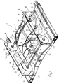
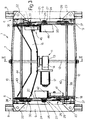
- Number 1 in the accompanying drawings indicates an actuator assembly for fitment between the floor 2 ( Figure 4) of a vehicle (not shown), particularly a motor vehicle, and the seat portion 3 of a seat 4 presenting a seatback 5 fitted adjustably to a rear portion of seat portion 3.
- Assembly 1 provides for adjusting the position of seat 4 in relation to floor 2, and comprises two facing lateral blocks 6 dimensionally and geometrically identical to each other, and a central block 7 extending between blocks 6 ( Figure 1).
- each block 6 comprises a longitudinal guide 8 parallel to guide 8 of the other block 6 and fitted integrally, in use, to floor 2; and an elongated slide 9 fitted in sliding manner to respective guide 8; and central block 7 comprises a pair of cross members 10 extending between slides 9 and presenting respective opposite end portions connected integral with respective opposite longitudinal ends of slides 9.
- the space defined between slides 9 and cross members 10 houses an actuator assembly 11 for moving slides 9 synchronously back and forth and into given corresponding positions along guides 8.
- Assembly 11 comprises a screw 12 extending longitudinally between cross members 10, parallel to guides 8, and the end portions of which are connected integral with respective intermediate portions of cross members 10.
- Screw 12 is fitted with a nut screw 13 in turn fitted in rotary and axially fixed manner to a hollow supporting body 14.
- Body 14 is connected integral with a further fixed cross member 15 extending between cross members 10, and the end portions of which are each connected integral with a respective guide 8, and more specifically with the surface of guide 8 facing floor 2 ( Figures 3 and 4).
- Nut screw 13 is rotated about its axis by a worm-helical gear drive 16 ( Figure 4) housed in body 14 and powered by a motor 17 ( Figures 1 and 3) supported by body 14 and cross member 15.
- slides 9 are moved along guides 8 by the user, and actuator assembly 11 is replaced by known hand-operated lock elements interposed between guides 8 and respective slides 9, for selectively locking slides 9 in a number of axial positions in relation to guides 8.
- assembly 1 also comprises two longitudinal side members 18 and 19, each forming part of a respective block 6, each extending upwards from a respective slide 9, and each comprising ( Figures 1 and 2) a bottom portion or plate 20 connected integral with respective slide 9 by means of a pair of brackets 22, 23 ( Figure 3), and a top portion or plate 24 which, together with the other top plate 24, supports the bottom (not shown) of seat portion 3.
- Top plates 24 are connected to respective bottom plates 20 via the interposition of an actuating unit 25 for vertically adjusting the position of top plates 24 in relation to respective bottom plates 20 and, consequently, the position of seat portion 3 in relation to guides 8.
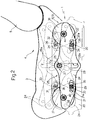
- plates 20 and 24 of each side member 18, 19 lie in respective side by side vertical planes with plate 24 outwards of plate 20; and each is substantially rectangular with a substantially horizontal longitudinal axis. More specifically, plate 20 of each side member 18, 19 is substantially the same length as plate 24, and presents a cylindrical pin 26 projecting transversely in relation to guides 8 from the outer surface of plate 20 towards respective plate 24, and which forms the guide of a respective guide-slide assembly 27 forming part of actuating unit 25.
- the slide of each assembly 27 is defined by a central portion 28 of plate 24 ( Figure 2), which presents a straight slot 28a extending transversely to the longitudinal axis of respective plate 24 and engaged in rotary and transversely sliding manner by respective pin 26.
- Plates 20 and 24 of each side member 18, 19 are also connected to each other by a further two guide-slide assemblies 29 and 30 also forming part of actuating unit 25 and located at the opposite axial ends of plate 20, symmetrically in relation to assembly 27.
- the slides of assemblies 29 and 30 are defined by respective lateral portions 31 and 32 of plates 24, which present respective slots 31a and 32a extending on either side of and perpendicularly to respective slot 28a; while the guides of assemblies 29 and 30 are movable guides defined by respective pins 33 and 34 presenting respective axes 35 and 36 parallel to pin 26, and extending in rotary and transversely sliding manner through respective slots 31a and 32a.
- Pins 33 and 34 of each side member 18, 19 are connected integral with respective cranks 37 and 38 perpendicular to pins 33 and 34 and extending at least partly between plates 20 and 24.
- the two cranks 37 are mounted parallel to each other on plates 20 of respective side members 18 and 19, and are connected in rotary manner to respective plates 20 so as to rotate, in relation to plates 20, about a common axis 39 perpendicular to guides 8 and coincident with the axis of a drive rod 40 forming part of block 7 and extending between plates 20 to connect cranks 37 integral with each other.
- the two cranks 37 and rod 40 together form the output member of an actuator 41 forming part of actuating unit 11 and comprising a motor 42 supported on plate 20 of side member 18, and a gear drive 42a (shown partly in Figure 1) - preferably a planocentric drive - interposed between motor 42 and rod 40 and housed inside a respective casing.
- the two cranks 38 are mounted parallel to each other on plates 20 of respective side members 18 and 19, and are connected in rotary manner to respective plates 20 so as to rotate, in relation to plates 20, about a common axis 43 perpendicular to guides 8 and coincident with the axis of a drive rod 44 extending between plates 20 to connect cranks 38 integral with each other.
- the two cranks 38 and rod 44 together form the output member of an actuator 45 identical to actuator 41 and also forming part of actuating unit 11.
- Actuator 45 is connected to respective plate 20 on the opposite side of the common axis of pins 26 to actuator 41, and comprises a motor 46 supported on plate 20 of side member 19, and a known drive identical to drive 42a of actuator 41.
- motors 42 and 46 are replaced by hand-operated knobs (not shown) for rotating respective cranks 37, 38.
- the longitudinal position of seat portion 3 in relation to floor 2 is adjusted by moving slides 9 in one direction or the other in relation to respective guides 8 by means of motor 17; while the vertical position of seat portion 3 is adjusted by simultaneously operating motors 42 and 46 which, via respective actuators 41 and 45, rotate respective cranks 37 and 38 in opposite directions about respective axes 39 and 43, so that respective pins 33 and 34 slide in opposite directions along respective slots 31 and 32.
- operation of motor 42 moves the two pins 33 along respective slots 31 so as to rock seat portion 3 about an instantaneous transverse axis coincident with axis 36 of pins 34 and located on the opposite side of vertical assembly 27 to actuator 41. Due to the presence of assembly 27, displacement of pins 33 along slots 31 by motor 42 results, when motor 46 is idle, in rotation of seat portion 3 about axis 36 of pins 34, and in vertical displacement of axis 35.
- operation of motor 46 moves the two pins 34 along respective slots 32 so as to rock seat portion 3 about an instantaneous transverse axis coincident with axis 35 of pins 33 and located on the opposite side of vertical assembly 27 to actuator 45 and axis 36.
- horizontal displacement of pins 34 along slots 32 by motor 46 results, when motor 42 is idle, in rotation of seat portion 3 about axis 35 of pins 33, and in vertical displacement of axis 36.
- assembly 1 therefore presents the advantage of enabling vertical adjustment of seat portion 3 with no change in its longitudinal position, while at the same time enabling controlled forward and/or backward rocking of the seat portion in relation to floor 2.
- assembly 1 is readily adaptable to seats of any width by simply adapting central portion 7, and more specifically by using transverse rods 40, 44 and cross members 10 of different lengths.
- rods 40 and 44 are relatively economical in the event, as stated, planocentric drives are used for transmitting motion to cranks 37, 38; in which case, transverse rods 40 and 44 may be straightforward smooth rods, unlike known seats normally featuring transverse rods consisting of high-cost screws.
- guides 8 may be formed from ordinary light metal U sections with no additional processing which, in the case of known guides, is indispensable for connecting the racks to the guides.
- motors 42 and 46 controlling seat portion 3 are each connected to a respective side member 18, 19 and housed inside the space between side members 18 and 19 provides for solving various problems as regards size and interference of motors 42 and 46 with the vehicle floor.
- screw 12 controlling slides 9 is axially fixed, and more specifically presents both ends connected integral with cross members 10, provides for eliminating in-service oscillation, and hence jamming, of screw 12.
- screw 12 is connected to cross members 10 and the provision of cross members 10 for connecting side members 18 and 19 provide for forming a highly rigid carriage, the rigidity of which, following fitment of assembly 1 to seat 4, contributes towards greatly improving the rigidity of the frame (not shown) of seat 4.
- the travel of the above carriage is substantially equal to the length of guides 8, and, even when the carriage is set to the limit stop position, no moving parts project outwards of the carriage or, consequently, outwards of seat 4.
Landscapes
- Engineering & Computer Science (AREA)
- Aviation & Aerospace Engineering (AREA)
- Transportation (AREA)
- Mechanical Engineering (AREA)
- Seats For Vehicles (AREA)
Applications Claiming Priority (2)
| Application Number | Priority Date | Filing Date | Title |
|---|---|---|---|
| ITTO930595A IT1260971B (it) | 1993-08-06 | 1993-08-06 | Gruppo attuatore, particolarmente per la movimentazione di sedili per veicoli |
| ITTO930595 | 1993-08-06 |
Publications (2)
| Publication Number | Publication Date |
|---|---|
| EP0639477A1 true EP0639477A1 (fr) | 1995-02-22 |
| EP0639477B1 EP0639477B1 (fr) | 1997-11-12 |
Family
ID=11411678
Family Applications (1)
| Application Number | Title | Priority Date | Filing Date |
|---|---|---|---|
| EP94112205A Expired - Lifetime EP0639477B1 (fr) | 1993-08-06 | 1994-08-04 | Ensemble d'actionnement pour sièges de véhicules |
Country Status (4)
| Country | Link |
|---|---|
| EP (1) | EP0639477B1 (fr) |
| DE (1) | DE69406735T2 (fr) |
| ES (1) | ES2109566T3 (fr) |
| IT (1) | IT1260971B (fr) |
Cited By (5)
| Publication number | Priority date | Publication date | Assignee | Title |
|---|---|---|---|---|
| WO1999019966A1 (fr) * | 1997-10-09 | 1999-04-22 | Ut Automotive Dearborn, Inc. | Appareil multifonctions avec mecanisme a mouvement intermittent |
| WO2000034070A1 (fr) * | 1998-12-08 | 2000-06-15 | Dura Global Technologies, Inc. | Configuration d'entrainement horizontale simple pour dispositif de reglage du siege |
| DE10000906C1 (de) * | 2000-01-12 | 2001-02-01 | Faure Bertrand Sitztech Gmbh | Kraftfahrzeugsitz |
| DE10060715C1 (de) * | 2000-12-07 | 2002-02-28 | Faurecia Autositze Gmbh & Co | Kraftfahrzeugsitz |
| US11279261B2 (en) * | 2016-08-15 | 2022-03-22 | Aisin Seiki Kabushiki Kaisha | Vehicular seat adjustment device, position adjustment control device, and vehicular seat adjustment method |
Citations (3)
| Publication number | Priority date | Publication date | Assignee | Title |
|---|---|---|---|---|
| EP0057617A2 (fr) * | 1981-01-21 | 1982-08-11 | COMPAGNIE INDUSTRIELLE DE MECANISMES en abrégé C.I.M. Société dite: | Dispositif de réglage de la position d'un élément, notamment d'un siège de véhicule |
| DE4002946A1 (de) * | 1990-02-01 | 1991-08-08 | Brose Fahrzeugteile | Vorrichtung zur befestigung eines elektronikgehaeuses fuer eine sitzverstelleinrichtung |
| EP0589421A1 (fr) * | 1992-09-25 | 1994-03-30 | FERRERO GIULIO S.p.A. | Siège de véhicule réglable |
-
1993
- 1993-08-06 IT ITTO930595A patent/IT1260971B/it active IP Right Grant
-
1994
- 1994-08-04 EP EP94112205A patent/EP0639477B1/fr not_active Expired - Lifetime
- 1994-08-04 ES ES94112205T patent/ES2109566T3/es not_active Expired - Lifetime
- 1994-08-04 DE DE69406735T patent/DE69406735T2/de not_active Expired - Fee Related
Patent Citations (3)
| Publication number | Priority date | Publication date | Assignee | Title |
|---|---|---|---|---|
| EP0057617A2 (fr) * | 1981-01-21 | 1982-08-11 | COMPAGNIE INDUSTRIELLE DE MECANISMES en abrégé C.I.M. Société dite: | Dispositif de réglage de la position d'un élément, notamment d'un siège de véhicule |
| DE4002946A1 (de) * | 1990-02-01 | 1991-08-08 | Brose Fahrzeugteile | Vorrichtung zur befestigung eines elektronikgehaeuses fuer eine sitzverstelleinrichtung |
| EP0589421A1 (fr) * | 1992-09-25 | 1994-03-30 | FERRERO GIULIO S.p.A. | Siège de véhicule réglable |
Cited By (6)
| Publication number | Priority date | Publication date | Assignee | Title |
|---|---|---|---|---|
| US6018223A (en) * | 1995-04-28 | 2000-01-25 | Lear Automotive Dearborn, Inc. | Multi-functional apparatus employing an intermittent motion mechanism |
| WO1999019966A1 (fr) * | 1997-10-09 | 1999-04-22 | Ut Automotive Dearborn, Inc. | Appareil multifonctions avec mecanisme a mouvement intermittent |
| WO2000034070A1 (fr) * | 1998-12-08 | 2000-06-15 | Dura Global Technologies, Inc. | Configuration d'entrainement horizontale simple pour dispositif de reglage du siege |
| DE10000906C1 (de) * | 2000-01-12 | 2001-02-01 | Faure Bertrand Sitztech Gmbh | Kraftfahrzeugsitz |
| DE10060715C1 (de) * | 2000-12-07 | 2002-02-28 | Faurecia Autositze Gmbh & Co | Kraftfahrzeugsitz |
| US11279261B2 (en) * | 2016-08-15 | 2022-03-22 | Aisin Seiki Kabushiki Kaisha | Vehicular seat adjustment device, position adjustment control device, and vehicular seat adjustment method |
Also Published As
| Publication number | Publication date |
|---|---|
| DE69406735T2 (de) | 1998-04-09 |
| ITTO930595A1 (it) | 1995-02-06 |
| IT1260971B (it) | 1996-04-29 |
| DE69406735D1 (de) | 1997-12-18 |
| ITTO930595A0 (it) | 1993-08-06 |
| EP0639477B1 (fr) | 1997-11-12 |
| ES2109566T3 (es) | 1998-01-16 |
Similar Documents
| Publication | Publication Date | Title |
|---|---|---|
| US7770972B2 (en) | Seat lumbar actuator | |
| US5112018A (en) | Vehicle seat track apparatus | |
| KR100687021B1 (ko) | 시트용 받침대 조정 장치 및 그 받침대 슬라이더 및 장착 플레이트, 시트 받침대의 위치 조정 방법, 및 모듈화된 받침대 조정 장치를 조립하는 방법 | |
| US7571964B2 (en) | Electric telescopic apparatus for vehicle seat | |
| GB2153218A (en) | Seat with multiple adjustments operable by an electric motor | |
| US5860319A (en) | Reduced noise drive block for vehicle seat adjuster | |
| US3951004A (en) | Multiple position seat adjustment mechanism | |
| EP0589421B1 (fr) | Siège de véhicule réglable | |
| EP0260631B1 (fr) | Dispositif de réglage de l'inclinaison du siège arrière d'un véhicule | |
| CN102653248A (zh) | 具有数个调节功能的车辆座椅的电动调节设备的致动器 | |
| EP0639477B1 (fr) | Ensemble d'actionnement pour sièges de véhicules | |
| CN114542877A (zh) | 一种汽车中控屏幕调节机构 | |
| GB2259248A (en) | Lumbar support apparatus for vehicular seat | |
| CN115352520B (zh) | 一种方向盘调节装置及控制方法 | |
| CN221137795U (zh) | 座椅头枕 | |
| CN2745784Y (zh) | 一种电动汽车座椅 | |
| EP0099414B1 (fr) | Appareil à glissières pour siège de véhicule | |
| TWI856374B (zh) | 電動座椅角度調整 | |
| EP0655364B1 (fr) | Siège réglable de véhicule | |
| CN223384387U (zh) | 一种滑移翻转屏运动装置 | |
| WO2016075594A1 (fr) | Appareil radiologique avec un système de déplacement de table avec tiges à angle variable | |
| KR100837520B1 (ko) | 시트의 쿠션 익스텐션 장치 | |
| CN221541353U (zh) | 座椅及其腿支托组件 | |
| EP1099523B1 (fr) | Machine automatique a former les bords | |
| CN120116813A (zh) | 一种实现零重力功能的分段式座椅滑轨系统 |
Legal Events
| Date | Code | Title | Description |
|---|---|---|---|
| PUAI | Public reference made under article 153(3) epc to a published international application that has entered the european phase |
Free format text: ORIGINAL CODE: 0009012 |
|
| AK | Designated contracting states |
Kind code of ref document: A1 Designated state(s): DE ES FR GB IT |
|
| 17P | Request for examination filed |
Effective date: 19950812 |
|
| 17Q | First examination report despatched |
Effective date: 19960424 |
|
| GRAG | Despatch of communication of intention to grant |
Free format text: ORIGINAL CODE: EPIDOS AGRA |
|
| GRAH | Despatch of communication of intention to grant a patent |
Free format text: ORIGINAL CODE: EPIDOS IGRA |
|
| GRAH | Despatch of communication of intention to grant a patent |
Free format text: ORIGINAL CODE: EPIDOS IGRA |
|
| GRAA | (expected) grant |
Free format text: ORIGINAL CODE: 0009210 |
|
| AK | Designated contracting states |
Kind code of ref document: B1 Designated state(s): DE ES FR GB IT |
|
| ITF | It: translation for a ep patent filed | ||
| REF | Corresponds to: |
Ref document number: 69406735 Country of ref document: DE Date of ref document: 19971218 |
|
| ET | Fr: translation filed | ||
| REG | Reference to a national code |
Ref country code: ES Ref legal event code: FG2A Ref document number: 2109566 Country of ref document: ES Kind code of ref document: T3 |
|
| PGFP | Annual fee paid to national office [announced via postgrant information from national office to epo] |
Ref country code: GB Payment date: 19980810 Year of fee payment: 5 |
|
| PGFP | Annual fee paid to national office [announced via postgrant information from national office to epo] |
Ref country code: ES Payment date: 19980811 Year of fee payment: 5 |
|
| PGFP | Annual fee paid to national office [announced via postgrant information from national office to epo] |
Ref country code: FR Payment date: 19980814 Year of fee payment: 5 |
|
| PGFP | Annual fee paid to national office [announced via postgrant information from national office to epo] |
Ref country code: DE Payment date: 19980831 Year of fee payment: 5 |
|
| PLBE | No opposition filed within time limit |
Free format text: ORIGINAL CODE: 0009261 |
|
| STAA | Information on the status of an ep patent application or granted ep patent |
Free format text: STATUS: NO OPPOSITION FILED WITHIN TIME LIMIT |
|
| 26N | No opposition filed | ||
| PG25 | Lapsed in a contracting state [announced via postgrant information from national office to epo] |
Ref country code: GB Free format text: LAPSE BECAUSE OF NON-PAYMENT OF DUE FEES Effective date: 19990804 |
|
| PG25 | Lapsed in a contracting state [announced via postgrant information from national office to epo] |
Ref country code: ES Free format text: LAPSE BECAUSE OF NON-PAYMENT OF DUE FEES Effective date: 19990805 |
|
| GBPC | Gb: european patent ceased through non-payment of renewal fee |
Effective date: 19990804 |
|
| PG25 | Lapsed in a contracting state [announced via postgrant information from national office to epo] |
Ref country code: FR Free format text: LAPSE BECAUSE OF NON-PAYMENT OF DUE FEES Effective date: 20000428 |
|
| PG25 | Lapsed in a contracting state [announced via postgrant information from national office to epo] |
Ref country code: DE Free format text: LAPSE BECAUSE OF NON-PAYMENT OF DUE FEES Effective date: 20000601 |
|
| REG | Reference to a national code |
Ref country code: FR Ref legal event code: ST |
|
| REG | Reference to a national code |
Ref country code: ES Ref legal event code: FD2A Effective date: 20000911 |
|
| PG25 | Lapsed in a contracting state [announced via postgrant information from national office to epo] |
Ref country code: IT Free format text: LAPSE BECAUSE OF NON-PAYMENT OF DUE FEES Effective date: 20050804 |