EP0639496A2 - Un bateau, en particulier une annexe pour embarcations et navires ou semblables - Google Patents
Un bateau, en particulier une annexe pour embarcations et navires ou semblables Download PDFInfo
- Publication number
- EP0639496A2 EP0639496A2 EP94111832A EP94111832A EP0639496A2 EP 0639496 A2 EP0639496 A2 EP 0639496A2 EP 94111832 A EP94111832 A EP 94111832A EP 94111832 A EP94111832 A EP 94111832A EP 0639496 A2 EP0639496 A2 EP 0639496A2
- Authority
- EP
- European Patent Office
- Prior art keywords
- boat
- floating
- hull
- rigid
- floating elements
- Prior art date
- Legal status (The legal status is an assumption and is not a legal conclusion. Google has not performed a legal analysis and makes no representation as to the accuracy of the status listed.)
- Withdrawn
Links
Images


Classifications
-
- B—PERFORMING OPERATIONS; TRANSPORTING
- B63—SHIPS OR OTHER WATERBORNE VESSELS; RELATED EQUIPMENT
- B63B—SHIPS OR OTHER WATERBORNE VESSELS; EQUIPMENT FOR SHIPPING
- B63B7/00—Collapsible, foldable, inflatable or like vessels
- B63B7/06—Collapsible, foldable, inflatable or like vessels having parts of non-rigid material
- B63B7/08—Inflatable
- B63B7/082—Inflatable having parts of rigid material
Definitions
- the invention relates to a boat, particularly to a service-boat for crafts, ships, or the like, having at least a central part of the hull made like a rigid shell and at least two peripheral floating elements.
- the invention provides a boat of the above mentioned kind, having peripheral floating elements which are secured to the central rigid part of the hull in an overturning way, alternatively in an active position, in which they are placed outside over the rigid part of the hull and in a storage or transport position, in which the said floating elements are placed inside the said central, rigid part of the hull.
- the floating elements can be locked in the active position by means of any releaseable means.
- floating elements it is preferably to use floating bodies formed by substantially cylindrical, inflatable chambers of rubberized canvas.
- two floating elements are provided, which are hinged along one longitudinal edge, at the respective broadside of the central rigid part of the hull, preferably at least along a straight section of it.
- the hinging means can be of any kind and for example of a kind similar to the usual hinges of metallic material or of plastic, too.
- the floating elements are hinged to the rigid part of the hull by means of longitudinal stripes of rubberized canvas made of one or more layers and being glued on one side to the floating element and on the other side to the adiacent longitudinal edge of the rigid part of the hull.
- the hinging means can be secured directly to the inflatable floating elements of rubberized canvas or with the interposition of stiffeners, as longitudinal members, or the like, which are incorporated in or fixed to the said floating bodies of rubberized canvas. This is particularly advantageous when the boat has considerable dimensions, like in the case of using it as a pleasure-boat, or when particular qualities of stability and strength are required.
- the transversal dimensions of the boats is notably reduced, in turning over the floating elements inwards, inside the rigid part of the hull.
- the said rigid part of the hull can show a width substantially corresponding to the double of the diameter of the floating elements.
- the boat is used essentially as a pleasure-boat, particularly of the kind known with the denomination of rubber-boat, then it is advantageous to provide a central rigid part of the hull showing a width greater than the double of the diameter or the transversal dimension of the lateral floating bodies.
- a free space is left between the two floating bodies for the stable or removable fittings and equipments, as for example the steering devices and the associated drivers' compartment, the different safety equipments and other kinds of equipments.
- the construction and the building of the before described boat according to the invention are simple and less expensive.
- the boat shows a reliability equal to that of the similar conventional boats.
- the floating elements overturned inside the shell, fill up a substantial part of the shell itself, avoiding also the disadvantage of burdening due to the considerable amount of water taken aboard by shipping waves in the case of following sea or in consequence to a lateral heeling of the boat.
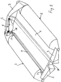
- Figure 1 shows a perspective view of a first embodiment of the boat according to the invention.
- Figures 2 and 3 are respectively a side view and a top view of the locking means for the floating elements in the active floating position.
- Figure 4 is a cross sectional view of the boat according to the preceding figures and with the floating elements in the active and inactive position.
- Figure 5 is a perspective view of a second embodiment of the boat according to the invention.
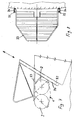
- Figure 6 is a cross-sectional view of the boat according to fig. 5.
- Figures 7 and 8 show the boat according to the invention in its position of transport, being suspended to a particular device for lifting and lowering away a boat, particularly advantageous for thr sailing boats.
- a boat particularly a service-boat for crafts, is formed by a rigid central part 1 of the hull comprising the part of the keel or underbody and the central part of the bow and of the stern.
- the rigid part of the hull can be built of any material, for example of plastic, of light alloy, or the like.
- the broadsides of the boat are formed by two inflatable lateral floating elements, wich are tubular shaped and of rubberized canvas and which extends themselves along a substantial section of the broadsides of the boat, the section being substantially straight.
- the floating elements 2 are hinged to the rigid part of the hull, i. e. to the longitudinal side edge 3 of the rigid parti 1 of the hull corresponding substantially to the lower edge of the broadsides, in an overturning way from the inside to the outside and viceversa, around an axis coinciding with the said longitudinal edge 3.
- each floating element 2 is provided by means of a longitudinal stripe 4 of rubberized canvas, or the like, formed by one or more layers, this stripe reaching from the bow to the stern of the boat and being glued to the adjacent, facing, internal bands of the floating elements 2 and of the corresponding lateral, longitudinal edge 3 of the rigid part 1 of the hull.
- the hinge 4 of rubberized canvas has also the funcion of connecting watertight the floating elements 2 to the rigid part 1 of the hull.
- the central rigid part of the bow and of the stern are connected to the corresponding ends of the floating elements 2 in a pliable and watertight manner, by means of correspondingly shaped walls 5 being also made out of rubberized canvas, or the like and which are glued to the peripheral edges facing eachother of the rigid part of the bow and of the stern and of the floating elements 2.
- the locking of the floating elements 2 in the active floating position, in which they are overturned outwards the rigid part 1 of the hull, is provided by four kinematic mechanisms, particularly scissors-like mechanisms, which are indicated with the reference number 6 and which are articulated between the ends at the bow and astern of each floating element and the corresponding rigid part of the bow and of the stern of the boat.
- the kinematic mechanisms are built in such a way, as to lock the floating elements 3 in a releaseable manner, both in the active floating position and in the inactive storage or transport position, in which they are overturned inwards, into the rigid part 1 of the hull.
- the floating elements occupy a volume of space with a transversal dimension corresponding substantially to the transversal dimension of the rigid part 1 of the hull.
- the kinematic locking mechanisms 6 being shown in detail in figures 2 and 3, comprise an L-shaped arm 7 which is pivotally mounted in 8, swinging around a logitudinal, horizontal axis parallel to the floating element 2 and a second arm 9 pivotally mounted in 10, oscillating around an axis parallel to the axis of oscillation of the L-shaped arm 7.
- Levers 13, 14 are articulated in 11 and 12 at the free ends of the arms 7 and 9 and swing around axis which are perpendicular to the axis of oscillation of the arms 7 and 9, the levers 13 and 14 being further linked toghether, swingably around an axis parallel to the axis of oscillation in 11 and 12, at an intermediate point between the two arms 7 and 9.
- a stop pin 16 is secured to the floating element 2, the said stop pin being substantially parallel to the free branch of the L-shaped arm 7 to which the lever 13 is articulated.
- the levers are aligned one with respect to the other and the L-shaped arm 7 abutes against the stop pin 16.
- the kinematic mechanism acts like a strut, locking the floating elements 2 against swinging inwards, into the hull.
- the relative angular displacement of the levers 13 and 14 cause the swinging of the floating elements 2 inwards into the rigid part 1 of the hull, in their inactive storage or transport position.
- the suitable arrangement of the pivot points 7, 10, 11, 12, 15, causes the levers 13, 14, to assume a vertical position relatively to the longitudinal axis of the boat in a protractor-like folded condition.
- the floating elements 2 can be provided with a longitudinal rigid bar 17 which for example is glued to the part of rubberized canvas and which is provided with a substantially vertical extension 18 at its ends at the bow and astern and to which the L-shaped arm 7 of the locking mechanism is articulated.
- a boat of the above described kind can show the following dimensions: length 2400 mm, width in the active floating position 1500 mm, width in the inactive storage or transport position 800 mm, height in the inactive position: 500 mm.
- the rigid part 1' of the hull comprises the keel or underbody, the broadsides, the complete transom and the entire bow of the boat, forming a small boat being completely closed at the bottom, at the bow, astern and along the boradsides.
- the floating elements On their sides abuting against the broadsides 20 of the central rigid small boat 1', the floating elements are provided with a concave recess 24 having a cross-section shaped substantially like a sector of a circle.
- the floating elements 22 On its side leaning against the broadsides 20 of the rigid small boat 1', the floating elements 22 are provided with a longitudinal stiffening element 25 being complementary shaped to the concave recess and reaching almost to the bow-end of the floating elements 22, whose bow-head is placed, in particular at the zone, at which the broadsides of the shell begins to taper in order to form the bow itself.
- said stiffening element 25 is hollow-made.
- the floating elements 22 can be made out of plastic material, for example fiberglass and it can be filled with plastic foam and/or it can be provided with internal stiffening rips.
- the other part of the floating elements 22 being inflatable is made of rubberized canvas.
- the rubberized canvas is joined in such a way as to form a cylindrical, tubular body 26 and is glued to the stiffening element 25 in a manner to cover the external side of the same one.
- the tubular body 26 can be glued to the internal side of the stiffening element.
- the rubberized canvas is not joint toghether in a tubular shaped body, but it is glued airtight with its opposite longitudinal edges to the upper and to the lower edges of the stiffening element 25, which forms a section of the peripheral wall of the tubular inflatable airtight body itself.
- the broadsides 20 of the rigid small boat 1' are shaped complementary to the stiffening element 25 so that, in the active floating position of the floating elements 22, the convex part of the broadsides fits in the concave recess of said stiffening element 25.
- the convex part of the broadsides 20 forms the bottom of a cavity which is shaped complementary to the stiffening element 25 so that in the active floating position of the floating elements 22 the stiffening elements 25 fits substantially completely in said complementary cavity in the broadside 20 of the rigid small boat 1', the lower and the upper walls of the cavity superposing in a predetermined measure on the peripheral upper and lower edges of the stiffening element 25.
- the floating elements 22 are close by half-shell shaped heads 27 of rigid material, for example of plastic, which are preferably built in one piece with the stiffening element 25, the end edge of the inflatable tubular body 26 being glued airtight to the peripheral edges of said heads.
- the hinging of the floating elements 22 to the rigid central shell 1' is provided by a stripe of rubberized canvas 28 made of one or more layers, the stripe being glued to the upper band of the floating elements 22 adjacent to the upper edge of the corresponding broadside 20 and to the upper band of the inner face of said broadside 20.
- the hinging stripes 28 reaches from astern to the bow and allow an opening and closing motion of the boat, during which the floating elements 22 performs an angular displacement combined with a traslation respectively upward and downward, with respect to the central rigid small boat 1' (see figure 6, arrow R, T).
- the locking of the floating elements 22 can be achieved in any way. Particularly, for example connecting the rigid small boat 1' and the floating elements 22 by means of eccentric pins or bolts engaging coinciding holes 29 of the floating element 22 and of the broadside 20 of the rigid small boat 1', or by means of eccentric pins or bolts being fastened to the floating element 22 and engaging holes in the broadside 20 of the rigid small boat 1'.
- the floating elements 22 are locked in the region at the bow by means of a transversal pin, carried by the same ones and engaging a hole 29 of the broadsides 20, preferably watertight, while astern the broadside 20 and the stiffening element 25 show coincident holes 29 for the engagement of a longitudinal pin or fastpin, the holes being provided in surfaces which are oriented transversally to the longitudinal axis of the hull.
- a boat according to this embodiment can show the following dimensions: length 2500 mm, witdth in the active floating position 1500 mm, width in the inactive storage or transport position 860 mm, hight in the inactive position 500 mm.
- the rigid part of the transom is provided with a central recess 30 for fitting an outbord motor.
- the recess 30 reenters on the inner side of the transom while the astern ends of the floating elements 2, 22 are shaped in a such way as to fit in complementary with the same one, in their inactive storage or transport position in which they are overturned inwards, inside the rigid shell 1, 1'. This allows to transport the boat with the outbord motor being placed in its operative position. Thus the boat can be lowered form the suitable supporting device, with the motor being just ready for use.
- the floating elements can be hinged to the rigid part 1, 1' of the hull also by means of traditional made hinges, for example comprising female elements being guided by a longitudinal pin or bar and being the hinge placed on the broadsides of the central rigid part.
- the hinge can extend itself along the entire broadside or a long a limitate section of it, for example at the ends of the hinging connection.
- a boat according to the invention is shown in its transport condition being suspended to a lifting and lowering device.
- This device 31 is particularly conceived for sailing boats with a slanted transom. It comprises a couple of parallel guides 32 being slanted from the upper to the bottom correspondingly to the transom.
- the guides 32 are formed by section bars with a C-like cross-section beign oriented with their open sides facing eachother.
- a cantilever bridge 33 is supported by two rods 34 being engaged in the guides 32.
- a coating of suitable antifriction material on the inner sides of the guides 32 for example gibs of antifriction sinthetic material, as PTFE, or the like, ensures the sliding.
- the lifting of the bridge 33 can be achieved in using one of the various lifts, or the like being provided on the sailing-boats, or by means of a suitable lifting device with a winch driven manually or by a motor.
- the projection of the bridge 33 over the stern of the boat reaches so far, that the boat according the invention fits under said bridge, in its inactive storage condition. Any kind of means can be provided for securing the boat to the lower side of the bridge 33.
- a possible gangway or the like can be hinged to the bridge 33, in an outwardly overturning way, over the astern side of the same one.
Landscapes
- Chemical & Material Sciences (AREA)
- Engineering & Computer Science (AREA)
- Combustion & Propulsion (AREA)
- Mechanical Engineering (AREA)
- Ocean & Marine Engineering (AREA)
- Filling Or Discharging Of Gas Storage Vessels (AREA)
- Handcart (AREA)
- Bridges Or Land Bridges (AREA)
Applications Claiming Priority (2)
| Application Number | Priority Date | Filing Date | Title |
|---|---|---|---|
| ITAL930003 | 1993-08-19 | ||
| IT93AL000003A ITAL930003A1 (it) | 1993-08-19 | 1993-08-19 | Imbarcazione, in particolare di servizio per imbarcazioni, navi o simili |
Publications (2)
| Publication Number | Publication Date |
|---|---|
| EP0639496A2 true EP0639496A2 (fr) | 1995-02-22 |
| EP0639496A3 EP0639496A3 (fr) | 1995-04-05 |
Family
ID=11333341
Family Applications (1)
| Application Number | Title | Priority Date | Filing Date |
|---|---|---|---|
| EP94111832A Withdrawn EP0639496A3 (fr) | 1993-08-19 | 1994-07-29 | Un bateau, en particulier une annexe pour embarcations et navires ou semblables. |
Country Status (2)
| Country | Link |
|---|---|
| EP (1) | EP0639496A3 (fr) |
| IT (1) | ITAL930003A1 (fr) |
Cited By (3)
| Publication number | Priority date | Publication date | Assignee | Title |
|---|---|---|---|---|
| WO2008131763A1 (fr) * | 2007-04-26 | 2008-11-06 | Viking Life-Saving Equipment A/S | Unité flottante d'évacuation |
| FR3036372A1 (fr) * | 2015-05-20 | 2016-11-25 | Nicolas Destouches | Embarcation pneumatique, avantageusement du type canot, annexe ou bateau |
| WO2018226123A1 (fr) * | 2017-06-07 | 2018-12-13 | Андрей Валерьевич ШАПЫГИН | Moyen de sauvetage |
Family Cites Families (4)
| Publication number | Priority date | Publication date | Assignee | Title |
|---|---|---|---|---|
| GB2135940A (en) * | 1983-01-03 | 1984-09-12 | Hennebutte Georges B L | Semi-rigid inflatable boat |
| FR2562862A1 (fr) * | 1984-04-16 | 1985-10-18 | Piveteau Francoise | Dispositif de repliage d'un catamaran |
| DE3507353A1 (de) * | 1985-03-01 | 1986-09-04 | Metzeler Kautschuk GmbH, 8000 München | Sportboot |
| FR2674496B1 (fr) * | 1991-03-26 | 1993-07-09 | Zodiac Int | Embarcation pneumatique gonflable avec tableau arriere non plan. |
-
1993
- 1993-08-19 IT IT93AL000003A patent/ITAL930003A1/it not_active Application Discontinuation
-
1994
- 1994-07-29 EP EP94111832A patent/EP0639496A3/fr not_active Withdrawn
Cited By (4)
| Publication number | Priority date | Publication date | Assignee | Title |
|---|---|---|---|---|
| WO2008131763A1 (fr) * | 2007-04-26 | 2008-11-06 | Viking Life-Saving Equipment A/S | Unité flottante d'évacuation |
| US8512089B2 (en) | 2007-04-26 | 2013-08-20 | Viking Life-Saving Equipment A/S | Floatable unit for evacuation purposes |
| FR3036372A1 (fr) * | 2015-05-20 | 2016-11-25 | Nicolas Destouches | Embarcation pneumatique, avantageusement du type canot, annexe ou bateau |
| WO2018226123A1 (fr) * | 2017-06-07 | 2018-12-13 | Андрей Валерьевич ШАПЫГИН | Moyen de sauvetage |
Also Published As
| Publication number | Publication date |
|---|---|
| ITAL930003A0 (it) | 1993-08-19 |
| ITAL930003A1 (it) | 1995-02-19 |
| EP0639496A3 (fr) | 1995-04-05 |
Similar Documents
| Publication | Publication Date | Title |
|---|---|---|
| US5277142A (en) | Variable-beam catamaran | |
| US6182598B1 (en) | Stair assembly for marine craft | |
| CN207773375U (zh) | 可折叠船只 | |
| PL242644B1 (pl) | Statek typu katamaran | |
| US20180065710A1 (en) | Extendable hull system movable betwen mono-hull and multi-hull configurations | |
| US3846858A (en) | Assembly for use in recreational activities | |
| CA2474299A1 (fr) | Ponton d'amarrage permettant l'evitage | |
| US5243924A (en) | Amphibious multihull boat | |
| US20120060737A1 (en) | Deployable assembly | |
| US5617810A (en) | Compact semi-collapsible watercraft | |
| AU2003212999B2 (en) | Collapsible catamaran | |
| US4287625A (en) | Portable boat dock | |
| US4800832A (en) | Recreational boat | |
| US3902441A (en) | Sailboat having retractable and self-ejectable hydraulic controls | |
| EP0639496A2 (fr) | Un bateau, en particulier une annexe pour embarcations et navires ou semblables | |
| US3930274A (en) | Assembly for use in recreational activities | |
| US5313908A (en) | Car topable catamaran with collapsible frame and universal tiller/rudder-mast daggerboard mounting constructions | |
| US3303520A (en) | Collapsible catamaran | |
| US20150291258A1 (en) | Convertible floating platform | |
| US4214546A (en) | Convertible amphibious vehicle | |
| US5090346A (en) | Multi-part ship construction system | |
| US3724011A (en) | Foldable boat | |
| US7314018B2 (en) | Collapsible boat hull | |
| JP7801873B2 (ja) | 救難艇 | |
| US2504256A (en) | Collapsible outboard motorboat |
Legal Events
| Date | Code | Title | Description |
|---|---|---|---|
| PUAI | Public reference made under article 153(3) epc to a published international application that has entered the european phase |
Free format text: ORIGINAL CODE: 0009012 |
|
| PUAL | Search report despatched |
Free format text: ORIGINAL CODE: 0009013 |
|
| AK | Designated contracting states |
Kind code of ref document: A2 Designated state(s): DE ES FR GB |
|
| AK | Designated contracting states |
Kind code of ref document: A3 Designated state(s): DE ES FR GB |
|
| 17P | Request for examination filed |
Effective date: 19950929 |
|
| STAA | Information on the status of an ep patent application or granted ep patent |
Free format text: STATUS: THE APPLICATION IS DEEMED TO BE WITHDRAWN |
|
| 18D | Application deemed to be withdrawn |
Effective date: 19970204 |