EP0639744A2 - Distributeur d'air - Google Patents
Distributeur d'air Download PDFInfo
- Publication number
- EP0639744A2 EP0639744A2 EP94810479A EP94810479A EP0639744A2 EP 0639744 A2 EP0639744 A2 EP 0639744A2 EP 94810479 A EP94810479 A EP 94810479A EP 94810479 A EP94810479 A EP 94810479A EP 0639744 A2 EP0639744 A2 EP 0639744A2
- Authority
- EP
- European Patent Office
- Prior art keywords
- air
- outlet chamber
- air outlet
- outflow
- distributor according
- Prior art date
- Legal status (The legal status is an assumption and is not a legal conclusion. Google has not performed a legal analysis and makes no representation as to the accuracy of the status listed.)
- Withdrawn
Links
Images




Classifications
-
- F—MECHANICAL ENGINEERING; LIGHTING; HEATING; WEAPONS; BLASTING
- F24—HEATING; RANGES; VENTILATING
- F24F—AIR-CONDITIONING; AIR-HUMIDIFICATION; VENTILATION; USE OF AIR CURRENTS FOR SCREENING
- F24F13/00—Details common to, or for air-conditioning, air-humidification, ventilation or use of air currents for screening
- F24F13/02—Ducting arrangements
- F24F13/06—Outlets for directing or distributing air into rooms or spaces, e.g. ceiling air diffuser
-
- F—MECHANICAL ENGINEERING; LIGHTING; HEATING; WEAPONS; BLASTING
- F24—HEATING; RANGES; VENTILATING
- F24F—AIR-CONDITIONING; AIR-HUMIDIFICATION; VENTILATION; USE OF AIR CURRENTS FOR SCREENING
- F24F13/00—Details common to, or for air-conditioning, air-humidification, ventilation or use of air currents for screening
- F24F13/02—Ducting arrangements
- F24F13/06—Outlets for directing or distributing air into rooms or spaces, e.g. ceiling air diffuser
- F24F13/068—Outlets for directing or distributing air into rooms or spaces, e.g. ceiling air diffuser formed as perforated walls, ceilings or floors
Definitions
- the invention relates to an air distributor for room ventilation, with an air outlet chamber having numerous air outflow openings and with an inflow channel provided for connection to an air conditioning duct and coaxial with the air outlet chamber.
- the invention has for its object to find an easy to manufacture air distributor that allows effective air distribution in the room to be ventilated with low air resistance.
- This object is achieved according to the invention in that the air outlet chamber has a plurality of regions of differently designed air outlet openings distributed in its circumferential direction, so that these regions have a different air outlet speed. In this way, it results that the air flowing out of some areas with increased speed exerts an induction effect on the surrounding areas, so that the air can penetrate deeply into the surrounding space with a relatively low outflow resistance from the air distributor.
- Such an air distributor can be produced in the simplest way by removing the air outlet openings from one for the sheet of the air outlet chamber provided sheet are punched out. In the case of designs with nozzle-like air outlets, these can easily be produced by deep drawing.
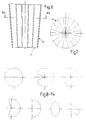
- the air distributor 1, 1 ' accordinging to FIG. 1 or 2 consists of a conical air outlet chamber 2 with a circular cross-section and an inflow duct 3 which adjoins its larger end in diameter with the same axis.
- the inflow duct 3 is provided for connection to a duct of an air conditioning system, so that it extends, for example, vertically from a ceiling into the room to be ventilated.
- each distributor 4 to 6 has an edge 10 which is curved outwards in the direction of flow.
- the distributors 4 to 6 arranged at a distance from one another have a permeable stowage surface 11 which has numerous holes arranged closely next to one another.
- the heating or cooling effect of the outflowing air is improved by increasing the air flow by induction.
- the numerous air outflow openings 7, 8, 7 ', 8' are designed in two sizes and each have the same size in an area 13, 14 running along a surface line of the air outlet chamber 2, 2 '.
- the amount of air flowing out and thereby also the induction effect can be changed by means of a control basket 16 which is rotatably enclosed in the air outlet chamber 2, 2 and lies against the wall of the control basket 16.
- This has spaced-apart wall parts 17, the number and width of which corresponds to that of one of the areas 13 or 14.
- outflow areas 13 or 14 are used to cover the wall parts 17 of the control cage 16
- the air flows through the other areas 14 or 13 or through the larger or smaller air outflow openings 7, 8; 7 ', 8' off, with correspondingly different ventilation effects.
- the control cage can be rotated to intermediate positions in which only a part of both outflow areas is closed.
- the latter is fastened to an axis 20 which is in line with the geometric axis of the air outlet chamber 2, 2' and which is in the floor 21 on the one hand and in the central region of two crossing struts 22, 23 on the other hand.
- the axis 20 is fastened to its base 24 and to cross struts 25, 26.
- the plate-shaped distributors 4 to 6 can also be attached to this axis 20.
- the rotation of the control cage can be done by manual drive, for example by means of a Bowden cable mechanism, by an actuator 28 according to FIGS. 15 and 16 or by a thermal drive 29 according to Fig. 17-19.
- the drive mechanism with the servomotor 28 is fastened to the bottom 24 of the air outlet chamber 2.2 ′ by means of angle pieces 31.
- the electrical cable 32 or a pneumatic line are led laterally outwards.
- the thermal drive is provided on the inflow side of the air outlet chamber 2, 2 ', so that the tubular container 33 containing the thermally expanding medium extends over the inflow-side chamber cross section and is therefore flowed against by the air.
- the control basket 16 automatically assumes an optimal control position as a function of the temperature of the air supplied by the air conditioning system.
- the cylinder-piston unit 36 of the thermal drive is fastened to a strut 22 of the air outlet chamber 2, 2 ′, and its piston rod 37 acts on an angle piece 38, which is fastened to a strut of the control cage 16.
- An adjusting screw 39 enables presetting of optimal positions by hand.
- an air distributor 1.1 ' due to its arrangement in the space 9 to be ventilated, should only emit air in certain circumferential areas of the air outlet chamber 2,2', e.g. when arranged along a wall of the room 9 or in a corner area, part of the areas 13, 14 can be closed off by an inserted wall, so that flow patterns result as shown in FIGS. 8 to 14.
Landscapes
- Engineering & Computer Science (AREA)
- Chemical & Material Sciences (AREA)
- Combustion & Propulsion (AREA)
- Mechanical Engineering (AREA)
- General Engineering & Computer Science (AREA)
- Duct Arrangements (AREA)
Applications Claiming Priority (2)
| Application Number | Priority Date | Filing Date | Title |
|---|---|---|---|
| CH249393 | 1993-08-20 | ||
| CH2493/93 | 1993-08-20 |
Publications (2)
| Publication Number | Publication Date |
|---|---|
| EP0639744A2 true EP0639744A2 (fr) | 1995-02-22 |
| EP0639744A3 EP0639744A3 (fr) | 1995-08-16 |
Family
ID=4235054
Family Applications (1)
| Application Number | Title | Priority Date | Filing Date |
|---|---|---|---|
| EP94810479A Withdrawn EP0639744A3 (fr) | 1993-08-20 | 1994-08-19 | Distributeur d'air. |
Country Status (1)
| Country | Link |
|---|---|
| EP (1) | EP0639744A3 (fr) |
Cited By (6)
| Publication number | Priority date | Publication date | Assignee | Title |
|---|---|---|---|---|
| DE19626884A1 (de) * | 1996-07-04 | 1998-01-08 | Schako Metallwarenfabrik | Luftauslaß |
| WO1998049499A1 (fr) * | 1997-04-15 | 1998-11-05 | ABB Fläkt Oy | Appareil de distribution de l'air d'amenee dans des pieces a ventiler |
| EP1318360A3 (fr) * | 2001-12-10 | 2005-08-17 | SCHAKO Klima Luft Ferdinand Schad KG | Sortie d'air |
| EP2199700A1 (fr) * | 2008-12-10 | 2010-06-23 | RC-Linja Oy | Dispositif d'alimentation en air |
| ITVA20130008A1 (it) * | 2013-02-07 | 2014-08-08 | Lino Alioli | Sistema di diffusione aria calda per complementi di arredo da esterni |
| WO2019211192A1 (fr) | 2018-05-02 | 2019-11-07 | Truma Gerätetechnik GmbH & Co. KG | Dispositif de distribution d'air |
Family Cites Families (5)
| Publication number | Priority date | Publication date | Assignee | Title |
|---|---|---|---|---|
| US3717081A (en) * | 1971-09-09 | 1973-02-20 | J Jakimas | Air conditioner diffuser |
| GB2120778A (en) * | 1982-05-20 | 1983-12-07 | Howorth Air Eng Ltd | Outlet device for an air conditioning system |
| DE8627384U1 (de) * | 1986-10-14 | 1987-10-15 | Schako Metallwarenfabrik Ferdinand Schad KG Zweigniederlassung Kolbingen, 7201 Kolbingen | Lüftungsauslaß-Bausatz |
| DE3810482A1 (de) * | 1988-03-26 | 1989-10-05 | Krantz H Gmbh & Co | Luftauslass zur erzeugung einer turbulenzarmen verdraengungsstroemung |
| DE4305471C2 (de) * | 1993-02-24 | 1997-06-19 | Fritz Juergen Eidmann | Deckenluftauslaß, insbesondere Luftauslaßschiene |
-
1994
- 1994-08-19 EP EP94810479A patent/EP0639744A3/fr not_active Withdrawn
Cited By (8)
| Publication number | Priority date | Publication date | Assignee | Title |
|---|---|---|---|---|
| DE19626884A1 (de) * | 1996-07-04 | 1998-01-08 | Schako Metallwarenfabrik | Luftauslaß |
| EP0816772A3 (fr) * | 1996-07-04 | 2000-03-22 | Schako Metallwarenfabrik Ferdinand Schad Kg | Sortie d'air |
| DE19626884C2 (de) * | 1996-07-04 | 2000-07-20 | Schako Metallwarenfabrik | Luftauslaß |
| WO1998049499A1 (fr) * | 1997-04-15 | 1998-11-05 | ABB Fläkt Oy | Appareil de distribution de l'air d'amenee dans des pieces a ventiler |
| EP1318360A3 (fr) * | 2001-12-10 | 2005-08-17 | SCHAKO Klima Luft Ferdinand Schad KG | Sortie d'air |
| EP2199700A1 (fr) * | 2008-12-10 | 2010-06-23 | RC-Linja Oy | Dispositif d'alimentation en air |
| ITVA20130008A1 (it) * | 2013-02-07 | 2014-08-08 | Lino Alioli | Sistema di diffusione aria calda per complementi di arredo da esterni |
| WO2019211192A1 (fr) | 2018-05-02 | 2019-11-07 | Truma Gerätetechnik GmbH & Co. KG | Dispositif de distribution d'air |
Also Published As
| Publication number | Publication date |
|---|---|
| EP0639744A3 (fr) | 1995-08-16 |
Similar Documents
| Publication | Publication Date | Title |
|---|---|---|
| DE4127608B4 (de) | Lufteinlaß | |
| DE102017115012B3 (de) | Belüftungskanal für eine Lüftungsvorrichtung eines Kraftfahrzeugs | |
| DE1454642B2 (de) | Einrichtung zur verteilung von luft zur belueftung und beheizung von kraftfahrzeugen | |
| DE2610818C2 (de) | Kühlvorrichtung für mittels eines Folienblaskopfes hergestellte Kunststoff-Schlauchfolien mit Luftkühlung | |
| DE2421788A1 (de) | Verstellbare luftzufuhrvorrichtung | |
| DE3879507T2 (de) | Luft-verteilungsanordnung. | |
| DE19518280A1 (de) | Vorrichtung zur Heizung und/oder Belüftung des Fahrgastraums | |
| EP0639744A2 (fr) | Distributeur d'air | |
| DE69711360T2 (de) | Vorrichtung zum kühlen von raumluft | |
| DE3124876A1 (de) | "weitwurfduese" | |
| DE4222064A1 (de) | Luftauslass | |
| DE3242215C2 (fr) | ||
| DE102005003849B3 (de) | Fahrzeugsitz mit Belüftungsvorrichtung | |
| EP2860467B1 (fr) | Sortie d'air | |
| DE3711520C2 (fr) | ||
| DE4013596C2 (fr) | ||
| DE2608252C2 (de) | Klimaleuchte | |
| DE4124850C2 (de) | Luftauslaß für Lüftungs- und Klimaanlagen | |
| EP0787954B1 (fr) | Dispositif de sortie d'air | |
| DE3222767C2 (de) | Luftdurchlaß für raumlufttechnische Anlagen | |
| DE2827910A1 (de) | Luftauslass, insbesondere deckenluftauslass | |
| DE2442378B2 (de) | Deckenluftauslafi | |
| EP1102016B1 (fr) | Radiateur | |
| DE1454642C (de) | Einrichtung zur Verteilung von Luft zur Belüftung und Beheizung von Kraft fahrzeugen | |
| CH446661A (de) | Vorrichtung zur Belüftung und Klimatisierung von Hörsälen und ähnlichen Versammlungsräumen |
Legal Events
| Date | Code | Title | Description |
|---|---|---|---|
| PUAI | Public reference made under article 153(3) epc to a published international application that has entered the european phase |
Free format text: ORIGINAL CODE: 0009012 |
|
| AK | Designated contracting states |
Kind code of ref document: A2 Designated state(s): AT CH DE FR LI |
|
| PUAL | Search report despatched |
Free format text: ORIGINAL CODE: 0009013 |
|
| AK | Designated contracting states |
Kind code of ref document: A3 Designated state(s): AT CH DE FR LI |
|
| 17P | Request for examination filed |
Effective date: 19960212 |
|
| GRAG | Despatch of communication of intention to grant |
Free format text: ORIGINAL CODE: EPIDOS AGRA |
|
| 17Q | First examination report despatched |
Effective date: 19980217 |
|
| GRAG | Despatch of communication of intention to grant |
Free format text: ORIGINAL CODE: EPIDOS AGRA |
|
| GRAH | Despatch of communication of intention to grant a patent |
Free format text: ORIGINAL CODE: EPIDOS IGRA |
|
| STAA | Information on the status of an ep patent application or granted ep patent |
Free format text: STATUS: THE APPLICATION IS DEEMED TO BE WITHDRAWN |
|
| 18D | Application deemed to be withdrawn |
Effective date: 19980929 |