EP0639924B1 - Dispositif pour contrôler le mode de codage pour un système numérique de codage de signaux vidéo - Google Patents
Dispositif pour contrôler le mode de codage pour un système numérique de codage de signaux vidéo Download PDFInfo
- Publication number
- EP0639924B1 EP0639924B1 EP19940113072 EP94113072A EP0639924B1 EP 0639924 B1 EP0639924 B1 EP 0639924B1 EP 19940113072 EP19940113072 EP 19940113072 EP 94113072 A EP94113072 A EP 94113072A EP 0639924 B1 EP0639924 B1 EP 0639924B1
- Authority
- EP
- European Patent Office
- Prior art keywords
- current
- coding
- frame
- frames
- block
- Prior art date
- Legal status (The legal status is an assumption and is not a legal conclusion. Google has not performed a legal analysis and makes no representation as to the accuracy of the status listed.)
- Expired - Lifetime
Links
- 230000033001 locomotion Effects 0.000 claims description 18
- 230000007704 transition Effects 0.000 claims 4
- 238000000034 method Methods 0.000 description 20
- 238000010586 diagram Methods 0.000 description 6
- 108091026890 Coding region Proteins 0.000 description 2
- 230000003044 adaptive effect Effects 0.000 description 2
- 230000005540 biological transmission Effects 0.000 description 2
- 238000004364 calculation method Methods 0.000 description 1
- 238000004891 communication Methods 0.000 description 1
- 230000006835 compression Effects 0.000 description 1
- 238000007906 compression Methods 0.000 description 1
- 230000001934 delay Effects 0.000 description 1
- 230000003111 delayed effect Effects 0.000 description 1
- 230000001419 dependent effect Effects 0.000 description 1
- 238000006073 displacement reaction Methods 0.000 description 1
- 238000013139 quantization Methods 0.000 description 1
- 230000003595 spectral effect Effects 0.000 description 1
- 230000009466 transformation Effects 0.000 description 1
Images


Classifications
-
- H—ELECTRICITY
- H04—ELECTRIC COMMUNICATION TECHNIQUE
- H04N—PICTORIAL COMMUNICATION, e.g. TELEVISION
- H04N19/00—Methods or arrangements for coding, decoding, compressing or decompressing digital video signals
- H04N19/10—Methods or arrangements for coding, decoding, compressing or decompressing digital video signals using adaptive coding
- H04N19/102—Methods or arrangements for coding, decoding, compressing or decompressing digital video signals using adaptive coding characterised by the element, parameter or selection affected or controlled by the adaptive coding
- H04N19/103—Selection of coding mode or of prediction mode
- H04N19/107—Selection of coding mode or of prediction mode between spatial and temporal predictive coding, e.g. picture refresh
-
- H—ELECTRICITY
- H04—ELECTRIC COMMUNICATION TECHNIQUE
- H04N—PICTORIAL COMMUNICATION, e.g. TELEVISION
- H04N19/00—Methods or arrangements for coding, decoding, compressing or decompressing digital video signals
- H04N19/50—Methods or arrangements for coding, decoding, compressing or decompressing digital video signals using predictive coding
- H04N19/503—Methods or arrangements for coding, decoding, compressing or decompressing digital video signals using predictive coding involving temporal prediction
-
- H—ELECTRICITY
- H04—ELECTRIC COMMUNICATION TECHNIQUE
- H04N—PICTORIAL COMMUNICATION, e.g. TELEVISION
- H04N19/00—Methods or arrangements for coding, decoding, compressing or decompressing digital video signals
- H04N19/60—Methods or arrangements for coding, decoding, compressing or decompressing digital video signals using transform coding
- H04N19/61—Methods or arrangements for coding, decoding, compressing or decompressing digital video signals using transform coding in combination with predictive coding
Definitions
- the present invention is related to a digital video signal coding system according to the preamble of claim 1.
- video signals are transmitted in a digitized form.
- the video signals comprising a sequence of video frames is expressed in a digitized form, there is bound to occur a substantial amount of digital data, for each line in a video frame is defined by a sequence of digital data elements referred to as "pixels". Since, however, the available frequency bandwidth of a conventional transmission channel is limited, in order to transmit the substantial amount of digital data through the channel, use of a video signal encoding apparatus may become necessary to compress or reduce the volume of the data to be transmitted.
- the digital video signal can be normally compressed without seriously affecting its integrity because there usually exist certain correlationships or redundancies among some of the pixels in a single frame and also among those of neighboring frames.
- hybrid coding techniques together with statistical coding techniques, are known to be most effective.
- the adaptive intra/non-intra coding is a process of selecting video signals for a subsequent DCT process from either PCM(pulse code modulation) data of a current frame or motion compensated DPCM(differential pulse code modulation) data of a current frame adaptively, i.e., based on the variance thereof.
- the non-intra coding technique which is based on the concept of reducing the redundancies between neighboring frames, is used to predict the current frame according to the motion flow of an object and produce difference signals, referred to as displaced frame difference(DFD) signals, representing the difference between the current frame and its prediction.
- DFD displaced frame difference
- the resultant coded data length of the DFD signals is shorter than that of the corresponding intra coding signals.
- a scene in a video signal may be divided into two portions: i.e., moving objects; and the stationary background which contains no moving objects.
- moving objects When an object moves within the background of the scene, however, there will be an area which used to be hidden behind the moved object but becomes visible after the moving.
- this newly appeared area (hereinafter referred to as "uncovered area") should be coded by using the intra coding technique (and not the non-intra coding method inasmuch as there is no similarity or redundancy relating to the newly appeared portion in the previous frame, which can be used to predict the current frame).
- the coding mode selecting process purely based on the variance may incorrectly choose the non-intra coding, instead of the intra coding, to encode the newly appeared area.
- Document US-A-4,689,671 discloses a video signal encoding apparatus having detecting means for detecting an uncovered background region. These detecting means calculate the difference between the current input signal and the one-frame signal of the immediately preceding frame as well as a difference between the current frame and its motion compensated predicted frame. The detecting means further produces a coding sequence out of the calculated differences and determines an uncovered region from this coding sequence. Again, the computational effort for detecting uncovered regions is very high since several different frames as well as motion compensated predicted frames have to be computed.
- FIG. 1 there is illustrated a block diagram of a video encoder 100 in accordance with the preferred embodiment of the present invention.
- input video signals comprising a sequence of video frames each of which is, in turn, divided into a plurality of macroblocks, is first fed, on a macroblock-by-macroblock basis, into the video encoder 100 through a coding control device 105.
- the coding control device 105 then, when given three successive frames, i.e., a current frame and the previous and next frames in the input video signals, detects an uncovered area(s) within the current frame; provides an uncovered area map bearing such detected information for a coding mode control switch 115; and outputs the video signals of the current frame to a motion estimator 150, a signal combiner 110 and the coding mode control switch 115, as will be described more fully hereinbelow.
- the motion estimator 150 given the current and the previous frame stored in a frame store 160, predicts the current frame from the previous frame by way of generating a prediction result for each of the macroblocks within the current frame and providing the prediction result for a motion compensator 155.
- the signal combiner 110 subtracts a predictive block calculated by the motion compensator 155 based on the prediction result from the motion estimator 150, from each macroblock within the current frame; decides a coding, i.e., intra or non-intra coding, mode for each macroblock based on the variance thereof; and supplies as an output block either the original macroblock(PCM block) or the prediction error block(DPCM block) resulting from the subtraction, to the coding mode control device 115, depending on the decided coding mode.
- a coding i.e., intra or non-intra coding
- the coding mode control switch 115 then provides a two-dimensional Discrete Cosine Transformation processor 120 with either the macroblock supplied from the coding control device 105 or the output block from the signal combiner 110 according to the information contained in the uncovered area map from the coding control device 105. Specifically, when the macroblock under consideration within the current frame is determined to belong to an uncovered area(s) according to the information contained in the uncovered area map, acknowledging the macroblock should be coded by the intra coding technique, the coding mode control switch 115 provides the macroblock supplied from the coding control device 105. Otherwise, i.e., when the macroblock does not belong to the uncovered area(s) in the current frame, the coding mode control switch 115 provides the output block from the signal combiner 110. In this case, therefore, the coding mode for the macroblock is maintained as is determined by the signal combiner 110 in a conventional manner.
- Each resultant block from the coding mode control switch 115 is then transformed into its spectral components via the two-dimensional DCT processor 120 and supplied via a quantizer 125 as quantized video block to a variable length encoder 130 and then to a transmission buffer(not shown).
- the inversely quantized and transformed block via an inverse quantizer 135 and an inverse transformer 140 are, for a next prediction, supplied to the motion compensator 155 and the motion estimator 150 via a frame memory 160 in the form of a candidate predictive block that is retarded by one frame interval from the current frame now present at an output 106 of the coding control device 105.
- Fig. 2 there is illustrated an exemplary process performed by the coding control device 105 of Fig. 1, for detecting an uncovered area(s) in the current frame of the input video signals.
- an uncovered area denotes an area which used to be hidden behind a moving object but becomes visible after the moving.
- reference symbols F(N-1), F(N) and F(N+1) denote the previous, current and next frames, respectively.
- reference symbols A1 and A2 shall denote an uncovered area in the current frame F(N) after the movement of the moving object 200 between the previous and current frames F(N-1) and F(N), and an area covered in the next frame F(N+1) after the movement of an moving object 200 between the current and next frames F(N) and F(N+1), respectively.
- frame differences FD(N-1, N), FD(N, N+1), which have a logic-1 value in an area where there is a change between the two given frames are obtained between the previous and current frames, and between the current and next frames, respectively, by using a method disclosed in, e.g., Matthias Bierling and Robert Thomas, "Motion Compensated Field Interpolation using Hierarchically Structured Displacement Estimation," Signal Processing 11 , pp. 387-404 (1986), as shown in Fig. 2.
- the two Frame differences FD(N-1, N), FD(N, N+1) are then Exclusive-ORed to exclude the common area between the two frame differences FD(N-1, N) and FD(N, N+1), to thereby obtain two separate areas A1 and A2. Thereafter, to differentiate the uncovered area(s) A2 from the area(s) A1 covered in the next frame, the two separate areas A1 and A2 are ANDed with the frame differences FD(N-1, N), detecting the uncovered area(s) in the current frame F(N) as is required.
- FIG. 3 there is shown a more detailed block diagram of the coding control device 105 shown in Fig. 1, wherein the above described uncovered area detecting process can be carried out.
- the frame delay logic 305 retards the input video signals by one frame interval and supplies the retarded input video signals (e.g., the video signals of the current frame F(N) in Fig. 2) to the frame difference calculator 310 as its another input.
- the frame difference calculator 310 then performs the above-described frame difference calculation over its two inputs and transfers the resultant frame difference (e.g., the frame difference FD(N, N+1) in Fig. 2) to another frame delay logic 320 and an Exclusive-OR logic 330, respectively.
- the frame delay logic 320 delays the calculated frame difference by one frame interval, and supplies the delayed frame difference (e.g., the frame difference FD(N-1, N) in Fig. 2) to the Exclusive-OR logic 330 and an AND logic 350.
- the Exclusive-OR logic 330 performs the Exclusive-OR operation over its two input and supplies the result (e.g., the signal XOR[FD(N-1, N), FD(N, N+1)] shown in Fig. 2)to the AND logic 350.
- the AND logic 350 performs the AND operation over its two inputs to obtain an uncovered area map (e.g., the signal AND ⁇ FD[N-1,N], XOR[FD(N-1,N),FD(N,N+1)] ⁇ shown in Fig. 2) for the retarded input video signals (e.g., the current frame F(N) in Fig. 2), as is desired.
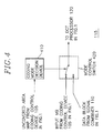
- FIG. 4 there is illustrated a more detailed block diagram of the coding mode control switch 115 of Fig. 1.
- the coding mode control switch 115 provides a two-dimensional DCT processor 120 shown in Fig. 1 with either a macroblock from the coding control device 105 or an output block from the signal combiner 110 according to the information contained in the uncovered map thereof from the coding control device 105 shown in Figs. 1 and 3. Specifically, when the macroblock under consideration within the current frame is determined to belong to an uncovered area(s) according to the information contained in the uncovered area map thereof, acknowledging the macroblock should be coded by the intra coding technique regardless of the coding mode decided in the signal combiner 110 for the macroblock, the coding mode control switch 115 provides the macroblock supplied from the coding control device 105.
- the coding mode control switch includes a coding mode decision device 410, and a mode control switch 420.
- the coding mode decision device 410 determines, by taking the uncovered area map as its input, whether the macroblock belongs to the uncovered area(s), by, e.g., counting the number of pixels within the macroblock, which belong to the uncovered area(s) in the uncovered map, and determining that the macroblock belongs to the uncovered area(s) when the counted number exceeds a predetermined value; and issues a switching control signal to the mode control switch 420 to select either the macroblock from the coding control device 105 when the macroblock belongs to the uncovered area(s), or the output block from the signal combiner 110, otherwise.
- an encoding apparatus for coding digital video signals describing a scene having at least one moving object and a stationary background, said digital video signals being represented by a series of video frames, each video frame being divided into a plurality of coding blocks, having a capability of adaptively selecting one of an intra coding technique and a non-intra coding technique to be applied to each coding block, which comprises:
- the encoder comprises a coding mode control device capable of accurately controlling the coding mode of each image data block in digital video signals.
Landscapes
- Engineering & Computer Science (AREA)
- Multimedia (AREA)
- Signal Processing (AREA)
- Compression Or Coding Systems Of Tv Signals (AREA)
Claims (3)
- Un appareil (100) de codage de signaux vidéo qui décrivent une scène incluant au moins un objet en mouvement (200) et un arrière-plan stationnaire, les signaux vidéo étant représentés par une séquence de trames vidéo (F(N - 1), F(N), F(N + 1) incluant une trame précédente (F(N - 1)), une trame actuelle (F(N)) et une trame suivante (F(N + 1)) et chaque trame vidéo (F(N - 1); F(N); F(N + 1) étant divisée en une série de blocs de codage qui comprend:caractérisé en ce quea) un moyen (310) de détermination d'une différence de trames actuelle (FD(N - 1, N)) et une différence de trames suivante (FD(N, N + 1)) où la différence de trames actuelle (FD(N - 1, N)) représente des différences entre la trame actuelle (F(N)) et la trame précédente (F(N - 1)) et la différence de trames suivante (FD(N, N + 1)) représente des différences entre la trame actuelle (F(N)) et la trame suivante (F(N + 1));b) un moyen (330) de détection d'une région de transition (A1, A2) incluant une région couverte (Al) et une région découverte (A2), où la région couverte (A1) est une zone de la trame suivante (F(N + 1)) qui est jusqu'ici visible dans la trame actuelle (F(N)) mais est cachée derrière l'objet en mouvement (200) après un mouvement de l'objet en mouvement (200) entre la trame actuelle (F(N)) et la suivante (F(N + 1)), et la région découverte (A2) désigne une zone de la trame actuelle (F(N)) qui était cachée derrière l'objet en mouvement (200) dans la trame précédente (F(N - 1)) et qui devient visible après le déplacement de l'objet en mouvement (200) entre la trame précédente (F(N - 1)) et la trame actuelle (F(N)); eten ce que l'appareil comprend en outrec) le moyen de détection (330) de région de transition est réalisé de manière à détecter les régions de transition en effectuant une opération exclusive-OU, ou XOR, entre la différence de trames actuelle (FD(N - 1, N)) et la différence de trames suivante (FD(N, N + 1)); etc) un moyen (350) d'identification de la région découverte (A2) en tant que partie commune de la région de transition (A1, A2) et de la différence de trames actuelle (FD(N - 1, N).
- L'appareil selon la revendication 1, qui comprend en outre:d) un moyen (145, 150, 155, 160) de production, sur la base de la trame précédente (F(N - 1)) et de la trame actuelle (F(N)), d'un bloc de prédiction qui correspond à chacun des blocs de codage de la trame actuelle (F(N));e) un moyen (115) de sélection, pour chacun desdits blocs de codage, soit du bloc de prédiction, soit du bloc de codage correspondant, en contrôlant si chacun desdits blocs de codage appartient ou non à la région découverte (A2) afin de fournir ainsi un bloc résultant; etf) un moyen (120, 125, 130) de codage du bloc résultant afin de fournir ainsi un signal vidéo codé.
- L'appareil selon la revendication 2, dans lequel c'est le bloc de codage qui est sélectionné pour être codé si le bloc de codage appartient à la région découverte (A2), et c'est le bloc de prédiction qui est choisi dans le cas contraire.
Applications Claiming Priority (2)
| Application Number | Priority Date | Filing Date | Title |
|---|---|---|---|
| KR9316211 | 1993-08-20 | ||
| KR1019930016211A KR0128859B1 (ko) | 1993-08-20 | 1993-08-20 | 적응적인 영상부호화 제어장치 |
Publications (3)
| Publication Number | Publication Date |
|---|---|
| EP0639924A2 EP0639924A2 (fr) | 1995-02-22 |
| EP0639924A3 EP0639924A3 (fr) | 1995-04-05 |
| EP0639924B1 true EP0639924B1 (fr) | 2000-01-12 |
Family
ID=19361654
Family Applications (1)
| Application Number | Title | Priority Date | Filing Date |
|---|---|---|---|
| EP19940113072 Expired - Lifetime EP0639924B1 (fr) | 1993-08-20 | 1994-08-22 | Dispositif pour contrôler le mode de codage pour un système numérique de codage de signaux vidéo |
Country Status (6)
| Country | Link |
|---|---|
| US (1) | US5528300A (fr) |
| EP (1) | EP0639924B1 (fr) |
| JP (1) | JP3717956B2 (fr) |
| KR (1) | KR0128859B1 (fr) |
| CN (1) | CN1066001C (fr) |
| DE (1) | DE69422558D1 (fr) |
Families Citing this family (8)
| Publication number | Priority date | Publication date | Assignee | Title |
|---|---|---|---|---|
| KR100211916B1 (ko) * | 1995-10-26 | 1999-08-02 | 김영환 | 물체 모양정보 부호화에서의 부호화타입과 모드의 결정방법 |
| EP1689189A3 (fr) * | 1996-11-07 | 2008-12-10 | Panasonic Corporation | Codeur d'image et decodeur d'image |
| CN100456324C (zh) * | 1999-12-28 | 2009-01-28 | 索尼公司 | 信号处理方法与设备 |
| KR100446083B1 (ko) * | 2002-01-02 | 2004-08-30 | 삼성전자주식회사 | 움직임 추정 및 모드 결정 장치 및 방법 |
| CN1214649C (zh) * | 2003-09-18 | 2005-08-10 | 中国科学院计算技术研究所 | 用于视频预测残差系数编码的熵编码方法 |
| CN101217663B (zh) * | 2008-01-09 | 2010-09-08 | 上海华平信息技术股份有限公司 | 用于编码器的图像像素块编码模式的快速选择方法 |
| KR101299249B1 (ko) * | 2008-08-29 | 2013-08-22 | 삼성테크윈 주식회사 | 디지털 촬영장치, 그 제어방법 및 제어방법을 실행시키기 위한 프로그램을 저장한 기록매체 |
| FR3120173A1 (fr) * | 2021-02-19 | 2022-08-26 | Orange | Détermination d’au moins un mode de codage d’image ou d’au moins un mode de décodage d’image, codage et décodage d’image utilisant une telle détermination |
Family Cites Families (13)
| Publication number | Priority date | Publication date | Assignee | Title |
|---|---|---|---|---|
| US3403226A (en) * | 1965-09-30 | 1968-09-24 | Bell Telephone Labor Inc | Reduced bandwidth dual mode encoding of video signals |
| JPS61114677A (ja) * | 1984-11-09 | 1986-06-02 | Nec Corp | 動画像信号の適応予測符号化復号化方式及びその装置 |
| US4689671A (en) * | 1985-06-27 | 1987-08-25 | Nec Corporation | Coding apparatus for moving object image |
| US4774570A (en) * | 1986-09-20 | 1988-09-27 | Sony Corporation | System for processing video signal for detecting changes in video data and security monitoring system utilizing the same |
| JPH082106B2 (ja) * | 1986-11-10 | 1996-01-10 | 国際電信電話株式会社 | 動画像信号のハイブリツド符号化方式 |
| US5040060A (en) * | 1987-12-01 | 1991-08-13 | Canon Kabushiki Kaisha | Image information transmission system with compression based on still-image redundancy |
| DE68909271T2 (de) * | 1988-02-23 | 1994-03-24 | Philips Nv | Verfahren und Anordnung zum Abschätzen des Bewegungsausmasses bei einem Bildelement eines Fernsehbildes. |
| JP2570384B2 (ja) * | 1988-05-30 | 1997-01-08 | 日本電気株式会社 | 動画像信号の符号化・復号化方式 |
| US5233629A (en) * | 1991-07-26 | 1993-08-03 | General Instrument Corporation | Method and apparatus for communicating digital data using trellis coded qam |
| JPH0564199A (ja) * | 1991-08-29 | 1993-03-12 | Pioneer Electron Corp | 画像監視装置 |
| KR940011881B1 (ko) * | 1991-12-23 | 1994-12-27 | 주식회사 금성사 | 움직임 검출 및 추정장치 |
| EP0561593B1 (fr) * | 1992-03-17 | 1997-07-16 | Sony Corporation | Dispositif pour la compression d'images |
| US5387938A (en) * | 1992-10-08 | 1995-02-07 | Matsushita Electric Industrial Co., Ltd. | Adaptive interframe/intraframe block coding method and apparatus |
-
1993
- 1993-08-20 KR KR1019930016211A patent/KR0128859B1/ko not_active Expired - Fee Related
-
1994
- 1994-08-20 CN CN94116856A patent/CN1066001C/zh not_active Expired - Lifetime
- 1994-08-22 DE DE69422558T patent/DE69422558D1/de not_active Expired - Lifetime
- 1994-08-22 EP EP19940113072 patent/EP0639924B1/fr not_active Expired - Lifetime
- 1994-08-22 US US08/294,530 patent/US5528300A/en not_active Expired - Lifetime
- 1994-08-22 JP JP19694594A patent/JP3717956B2/ja not_active Expired - Lifetime
Also Published As
| Publication number | Publication date |
|---|---|
| CN1066001C (zh) | 2001-05-16 |
| EP0639924A2 (fr) | 1995-02-22 |
| CN1111884A (zh) | 1995-11-15 |
| EP0639924A3 (fr) | 1995-04-05 |
| JP3717956B2 (ja) | 2005-11-16 |
| DE69422558D1 (de) | 2000-02-17 |
| KR950007522A (ko) | 1995-03-21 |
| JPH07154782A (ja) | 1995-06-16 |
| US5528300A (en) | 1996-06-18 |
| KR0128859B1 (ko) | 1998-04-10 |
Similar Documents
| Publication | Publication Date | Title |
|---|---|---|
| US5859668A (en) | Prediction mode selecting device in moving image coder | |
| KR0168458B1 (ko) | 움직임 보상을 갖는 프레임간 혼성 부호기에서의 왜곡을 감소시키는 장치 및 방법 그리고 그에 대한 부호화 시스템 | |
| US5434622A (en) | Image signal encoding apparatus using adaptive frame/field format compression | |
| US6282243B1 (en) | Apparatus and method for interframe predictive video coding and decoding with capabilities to avoid rounding error accumulation | |
| KR100291493B1 (ko) | 비디오 신호압축용 이동벡터 처리장치 | |
| CA2070757C (fr) | Appareil de prediction a compensation de mouvement | |
| JPH09179987A (ja) | 動きベクトル検出方法及び動きベクトル検出装置 | |
| EP0680217B1 (fr) | Appareil de décodage de signal vidéo capable de réduire les effets de bloc | |
| JP2911682B2 (ja) | ブロック整合のための基準としてモーションブロック毎に最少のビット数を用いるモーション補償 | |
| US5689312A (en) | Block matching motion estimation method | |
| KR20000053028A (ko) | 움직임 보상을 이용한 예측 코딩 방법 및 장치 | |
| KR0178195B1 (ko) | 벡터 양자화 방식을 이용한 영상 신호 부호화 장치 | |
| JPH08265765A (ja) | イメージ符号化システムとこれに用いる動き補償装置 | |
| EP0639924B1 (fr) | Dispositif pour contrôler le mode de codage pour un système numérique de codage de signaux vidéo | |
| JP3950211B2 (ja) | 動きベクトル符号化装置 | |
| KR100240620B1 (ko) | 양방향의 반화소 움직임 추정을 위한 대칭 탐색 윈도우를 형성하는 방법 및 장치 | |
| KR0174441B1 (ko) | 적응적 움직임 보상을 이용한 동영상 부호화 장치 | |
| KR100207419B1 (ko) | 부호화 비트발생율 제어방법 및 그 제어장치 | |
| KR100203638B1 (ko) | 반화소 단위 움직임 추정방법 | |
| KR100207391B1 (ko) | 적응적인 벡터 양자화를 이용한 영상 부호화 시스템 및 그의 움직임 정보 검출 방법 | |
| JPH09182081A (ja) | 動き補償予測符号化装置 | |
| KR100207418B1 (ko) | 부호화 비트발생율 제어방법 및 그 제어장치 | |
| KR20010041441A (ko) | 비디오 신호를 인코딩하기 위한 방법 및 장치 | |
| KR0124162B1 (ko) | 예측 부호화 방법 | |
| KR0178197B1 (ko) | 영역 분할을 이용한 영상 신호 부호화 장치 |
Legal Events
| Date | Code | Title | Description |
|---|---|---|---|
| PUAI | Public reference made under article 153(3) epc to a published international application that has entered the european phase |
Free format text: ORIGINAL CODE: 0009012 |
|
| PUAL | Search report despatched |
Free format text: ORIGINAL CODE: 0009013 |
|
| AK | Designated contracting states |
Kind code of ref document: A2 Designated state(s): DE FR GB NL |
|
| AK | Designated contracting states |
Kind code of ref document: A3 Designated state(s): DE FR GB NL |
|
| 17P | Request for examination filed |
Effective date: 19951004 |
|
| 17Q | First examination report despatched |
Effective date: 19971031 |
|
| GRAG | Despatch of communication of intention to grant |
Free format text: ORIGINAL CODE: EPIDOS AGRA |
|
| GRAG | Despatch of communication of intention to grant |
Free format text: ORIGINAL CODE: EPIDOS AGRA |
|
| GRAG | Despatch of communication of intention to grant |
Free format text: ORIGINAL CODE: EPIDOS AGRA |
|
| GRAH | Despatch of communication of intention to grant a patent |
Free format text: ORIGINAL CODE: EPIDOS IGRA |
|
| GRAH | Despatch of communication of intention to grant a patent |
Free format text: ORIGINAL CODE: EPIDOS IGRA |
|
| GRAA | (expected) grant |
Free format text: ORIGINAL CODE: 0009210 |
|
| AK | Designated contracting states |
Kind code of ref document: B1 Designated state(s): DE FR GB NL |
|
| PG25 | Lapsed in a contracting state [announced via postgrant information from national office to epo] |
Ref country code: NL Free format text: LAPSE BECAUSE OF FAILURE TO SUBMIT A TRANSLATION OF THE DESCRIPTION OR TO PAY THE FEE WITHIN THE PRESCRIBED TIME-LIMIT Effective date: 20000112 Ref country code: FR Free format text: LAPSE BECAUSE OF FAILURE TO SUBMIT A TRANSLATION OF THE DESCRIPTION OR TO PAY THE FEE WITHIN THE PRESCRIBED TIME-LIMIT Effective date: 20000112 |
|
| REF | Corresponds to: |
Ref document number: 69422558 Country of ref document: DE Date of ref document: 20000217 |
|
| PG25 | Lapsed in a contracting state [announced via postgrant information from national office to epo] |
Ref country code: DE Free format text: LAPSE BECAUSE OF FAILURE TO SUBMIT A TRANSLATION OF THE DESCRIPTION OR TO PAY THE FEE WITHIN THE PRESCRIBED TIME-LIMIT Effective date: 20000413 |
|
| NLV1 | Nl: lapsed or annulled due to failure to fulfill the requirements of art. 29p and 29m of the patents act | ||
| EN | Fr: translation not filed | ||
| PLBE | No opposition filed within time limit |
Free format text: ORIGINAL CODE: 0009261 |
|
| STAA | Information on the status of an ep patent application or granted ep patent |
Free format text: STATUS: NO OPPOSITION FILED WITHIN TIME LIMIT |
|
| 26N | No opposition filed | ||
| REG | Reference to a national code |
Ref country code: GB Ref legal event code: IF02 |
|
| REG | Reference to a national code |
Ref country code: GB Ref legal event code: 732E |
|
| REG | Reference to a national code |
Ref country code: GB Ref legal event code: 732E Free format text: REGISTERED BETWEEN 20130404 AND 20130410 |
|
| PGFP | Annual fee paid to national office [announced via postgrant information from national office to epo] |
Ref country code: GB Payment date: 20130821 Year of fee payment: 20 |
|
| REG | Reference to a national code |
Ref country code: GB Ref legal event code: PE20 Expiry date: 20140821 |
|
| PG25 | Lapsed in a contracting state [announced via postgrant information from national office to epo] |
Ref country code: GB Free format text: LAPSE BECAUSE OF EXPIRATION OF PROTECTION Effective date: 20140821 |