EP0639960B1 - Kniegelenksorthese - Google Patents
Kniegelenksorthese Download PDFInfo
- Publication number
- EP0639960B1 EP0639960B1 EP92914154A EP92914154A EP0639960B1 EP 0639960 B1 EP0639960 B1 EP 0639960B1 EP 92914154 A EP92914154 A EP 92914154A EP 92914154 A EP92914154 A EP 92914154A EP 0639960 B1 EP0639960 B1 EP 0639960B1
- Authority
- EP
- European Patent Office
- Prior art keywords
- rigid
- members
- knee
- brace
- strut
- Prior art date
- Legal status (The legal status is an assumption and is not a legal conclusion. Google has not performed a legal analysis and makes no representation as to the accuracy of the status listed.)
- Expired - Lifetime
Links
- 210000000629 knee joint Anatomy 0.000 title claims abstract description 40
- 210000003127 knee Anatomy 0.000 claims abstract description 75
- 210000002414 leg Anatomy 0.000 claims abstract description 42
- 210000000689 upper leg Anatomy 0.000 claims abstract description 41
- 238000004873 anchoring Methods 0.000 claims description 6
- 210000003414 extremity Anatomy 0.000 claims description 5
- 230000000069 prophylactic effect Effects 0.000 abstract description 14
- 230000033001 locomotion Effects 0.000 description 13
- 208000027418 Wounds and injury Diseases 0.000 description 12
- 208000014674 injury Diseases 0.000 description 12
- 230000006378 damage Effects 0.000 description 11
- 210000004439 collateral ligament Anatomy 0.000 description 7
- 210000003205 muscle Anatomy 0.000 description 7
- 210000004872 soft tissue Anatomy 0.000 description 5
- 230000007246 mechanism Effects 0.000 description 4
- 244000309466 calf Species 0.000 description 3
- 210000002683 foot Anatomy 0.000 description 3
- 210000003041 ligament Anatomy 0.000 description 3
- 201000008482 osteoarthritis Diseases 0.000 description 3
- 210000004417 patella Anatomy 0.000 description 3
- 230000002980 postoperative effect Effects 0.000 description 3
- 206010060820 Joint injury Diseases 0.000 description 2
- 208000016593 Knee injury Diseases 0.000 description 2
- 230000002159 abnormal effect Effects 0.000 description 2
- 210000001264 anterior cruciate ligament Anatomy 0.000 description 2
- 210000000988 bone and bone Anatomy 0.000 description 2
- 238000013461 design Methods 0.000 description 2
- 210000003141 lower extremity Anatomy 0.000 description 2
- 239000000463 material Substances 0.000 description 2
- 229920001084 poly(chloroprene) Polymers 0.000 description 2
- 206010039073 rheumatoid arthritis Diseases 0.000 description 2
- 230000008961 swelling Effects 0.000 description 2
- 210000002303 tibia Anatomy 0.000 description 2
- 208000025674 Anterior Cruciate Ligament injury Diseases 0.000 description 1
- 206010003694 Atrophy Diseases 0.000 description 1
- 208000017899 Foot injury Diseases 0.000 description 1
- 206010065433 Ligament rupture Diseases 0.000 description 1
- 208000005408 Metatarsus Varus Diseases 0.000 description 1
- 206010062575 Muscle contracture Diseases 0.000 description 1
- 206010049565 Muscle fatigue Diseases 0.000 description 1
- 229910000831 Steel Inorganic materials 0.000 description 1
- 241001227561 Valgus Species 0.000 description 1
- 241000469816 Varus Species 0.000 description 1
- 230000005856 abnormality Effects 0.000 description 1
- 239000000853 adhesive Substances 0.000 description 1
- 230000001070 adhesive effect Effects 0.000 description 1
- 210000003484 anatomy Anatomy 0.000 description 1
- 208000022542 ankle injury Diseases 0.000 description 1
- 230000037444 atrophy Effects 0.000 description 1
- 239000012141 concentrate Substances 0.000 description 1
- 238000010276 construction Methods 0.000 description 1
- 208000006111 contracture Diseases 0.000 description 1
- 238000012937 correction Methods 0.000 description 1
- 238000011161 development Methods 0.000 description 1
- 201000010099 disease Diseases 0.000 description 1
- 208000037265 diseases, disorders, signs and symptoms Diseases 0.000 description 1
- 230000000694 effects Effects 0.000 description 1
- 210000002082 fibula Anatomy 0.000 description 1
- 239000000945 filler Substances 0.000 description 1
- 238000004519 manufacturing process Methods 0.000 description 1
- 238000012986 modification Methods 0.000 description 1
- 230000004048 modification Effects 0.000 description 1
- 230000000399 orthopedic effect Effects 0.000 description 1
- 208000001297 phlebitis Diseases 0.000 description 1
- 210000002967 posterior cruciate ligament Anatomy 0.000 description 1
- 230000002787 reinforcement Effects 0.000 description 1
- 230000003014 reinforcing effect Effects 0.000 description 1
- 239000003381 stabilizer Substances 0.000 description 1
- 230000000087 stabilizing effect Effects 0.000 description 1
- 239000010959 steel Substances 0.000 description 1
Images


Classifications
-
- A—HUMAN NECESSITIES
- A61—MEDICAL OR VETERINARY SCIENCE; HYGIENE
- A61F—FILTERS IMPLANTABLE INTO BLOOD VESSELS; PROSTHESES; DEVICES PROVIDING PATENCY TO, OR PREVENTING COLLAPSING OF, TUBULAR STRUCTURES OF THE BODY, e.g. STENTS; ORTHOPAEDIC, NURSING OR CONTRACEPTIVE DEVICES; FOMENTATION; TREATMENT OR PROTECTION OF EYES OR EARS; BANDAGES, DRESSINGS OR ABSORBENT PADS; FIRST-AID KITS
- A61F5/00—Orthopaedic methods or devices for non-surgical treatment of bones or joints; Nursing devices ; Anti-rape devices
- A61F5/01—Orthopaedic devices, e.g. long-term immobilising or pressure directing devices for treating broken or deformed bones such as splints, casts or braces
- A61F5/0102—Orthopaedic devices, e.g. long-term immobilising or pressure directing devices for treating broken or deformed bones such as splints, casts or braces specially adapted for correcting deformities of the limbs or for supporting them; Ortheses, e.g. with articulations
- A61F5/0123—Orthopaedic devices, e.g. long-term immobilising or pressure directing devices for treating broken or deformed bones such as splints, casts or braces specially adapted for correcting deformities of the limbs or for supporting them; Ortheses, e.g. with articulations for the knees
-
- A—HUMAN NECESSITIES
- A61—MEDICAL OR VETERINARY SCIENCE; HYGIENE
- A61F—FILTERS IMPLANTABLE INTO BLOOD VESSELS; PROSTHESES; DEVICES PROVIDING PATENCY TO, OR PREVENTING COLLAPSING OF, TUBULAR STRUCTURES OF THE BODY, e.g. STENTS; ORTHOPAEDIC, NURSING OR CONTRACEPTIVE DEVICES; FOMENTATION; TREATMENT OR PROTECTION OF EYES OR EARS; BANDAGES, DRESSINGS OR ABSORBENT PADS; FIRST-AID KITS
- A61F5/00—Orthopaedic methods or devices for non-surgical treatment of bones or joints; Nursing devices ; Anti-rape devices
- A61F5/01—Orthopaedic devices, e.g. long-term immobilising or pressure directing devices for treating broken or deformed bones such as splints, casts or braces
- A61F5/0102—Orthopaedic devices, e.g. long-term immobilising or pressure directing devices for treating broken or deformed bones such as splints, casts or braces specially adapted for correcting deformities of the limbs or for supporting them; Ortheses, e.g. with articulations
- A61F2005/0132—Additional features of the articulation
- A61F2005/0137—Additional features of the articulation with two parallel pivots
Definitions
- This invention relates to an orthopedic support device, specifically a rear strut stabilized, derotational brace which may be used for prophylactic, functional and rehabilitative applications, particularly for a knee joint.
- Prophylactic knee braces are used to reduce the likelihood of injury during activities, particularly sports, in which high loads are placed on the knee joint.
- an objective of prophylactic knee braces is to provide some support for the joint without unduly restricting movement, thus reducing the risk of injury to a normal knee joint.
- Functional knee braces are used to support and stabilize injured joints, and hence, provide the strongest reinforcement for the knee. They often prohibit certain movements.
- Rehabilitative knee braces are used to support previously injured joints and are used extensively during post operative and rehabilitation periods. Their designs generally lie between prophylactic and functional braces in the amount of support they provide, and the degree of restriction they impose on joint movement is usually adjustable to provide only a specific range of desired motion.
- brace comprising first and second rigid support members.
- FR-A-2 581 859 there is known a stiff anterior cuff member secured to a rigid support member of a brace.
- GB-A-2 215 213 there are known braces having first and second rigid support members and first and second anchoring means as well as a rigid posterior strut.
- first and second rigid support members and first and second anchoring means there is no adjustability when the strut is attached to the terminal portions.
- US-A-4,088,130 there is known a rigid steel member along the thigh and one along the leg.
- FR-A-2 486 388 there are known rigid members, but these members are not on opposite sides right/left.
- Prophylactic supports for the knee joint include wraps of adhesive or elastic tape and reinforced neoprene sleeves. These devices, however, do not provide the support generally required.
- Prophylactic knee braces have been designed as single hinged vertical members placed laterally on one side of the leg and held by cuffs and straps to the thigh and the leg. Since the anatomy in the knee region is naturally offset, the fixation on one side cannot support the brace effectively. These braces tend to slip, thus exerting undue forces acting against the natural kinematics on the knee joint, and also concentrate forces laterally on the knee, which in some cases, increases the risk of medial collateral ligament or anterior cruciate ligament injury.
- Functional knee braces typically have medial and lateral rigid supports for the knee joint. Many of these devices have complicated hinge structures designed to accommodate or the femoral rollback which occurs upon flexion of the knee joint. Some of these braces use rigid molded thigh and leg cuffs to support the hinged lateral and medial support members. Other braces have utilized spiral structures and straps to connect the thigh and leg cuffs. These devices have not proven as effective as desired to protect against a knee injury and to support and stabilize an unstable knee or protect an injured knee. The major disadvantage of these rigid braces is slippage due to the conical shape of the lower extremity. With slippage, even a well designed brace can alter the kinematics of the knee and increase the risk of injury.
- knee brace uses an adjustable rigid or semi-rigid member encircling the knee joint which clamps lateral and medial pads against the knee joint.
- the proper operation of such braces depends on the exact fit on a specific knee, and therefore must be custom fitted. They are also bulky and generally more expensive. These devices tend to unduly restrict motion of the knee joint. Because of their more complex nature and bulkiness, interference with normal knee operation is higher if the hinge is misaligned.
- a knee brace which can be readily and easily adjusted to accommodate for individual knee characteristics and provide the surgeon/physiotherapist with a means for adjusting for abnormal knees for either improved brace fit, optimizing brace function/action for individual patients, or compensating for or controlling specific motions or actions. Adjustments may also be required or desirable during the course of treatment to accommodate for reduction in swelling, changes caused by treatment, or growth as in a child. It would also be desirable to have a single, or only a few basic sizes of the brace, which could be readily adapted to the circumstances, as opposed to the custom modeling and fabrication or the stocking of numerous sizes as required by many other braces.
- a rigid posterior strut is located in the popliteal space of the knee and to which all other parts of the brace are attached.
- the popliteal space behind the knee is the ideal location for fixing the reference point for a knee brace because (a) a rigid strut in the popliteal space does not interfere with the natural motion of the knee and/or the natural action of the leg; (b) any external forces acting on the knee through the mechanical strut are least likely to cause injury to the wearer, since the popliteal space is the only part of the knee where there is adequate soft tissue to absorb harmful energy; (c) the flexion and extension action of the knee relocates the brace into its proper position due to the action of the soft tissue in the popliteal region on the strut; and (d) the posterior strut provides a fixed reference point to which other functional parts of the brace may be attached giving design flexibility for prophylactic, functional and rehabilitative applications.
- the knee brace of this invention has a posterior strut to which vertical supports are connected by hinges, laterally applied forces at the knee are transmitted to the medial side of the brace, thus preventing injury to the medial collateral ligament. Also, medially directed forces are transmitted to the lateral side, bypassing the knee joint.
- the embodiment of the knee brace of this invention for prophylactic applications has a lateral inferior rigid support member which attaches to the leg, and a medial superior rigid support member which attaches to the lower thigh. Both of the rigid support members are pivotally connected on terminal portions of the rigid posterior strut. The pivot points are selected to reproduce the natural kinematics of the knee joint, including posterior femoral rollback.
- stiff cuff members preferably generally triangular in shape, are secured to the rigid support members and extend around the front of the thigh and calf and are pivotally connected to the opposite terminal portion of the posterior strut.
- the rigid support members are secured to the leg and thigh, respectively, by anchor means, preferably in the form of soft, resilient sleeves which may be held in place by straps secured such as by VELCRO fasteners. Any open spaces between the rigid support members, cuffs, thigh and calf are filled by the resilient sleeves, which, however, do not extend around the knee joint.
- the rigid posterior strut transfers forces acting on the knee around critical areas, dissipating some of the forces so transferred into the soft tissue surrounding the popliteal space.
- the action of the soft tissues on the posterior strut during normal extension/flexion of the knee causes the brace to self-center.
- the rigid posterior strut also serves as a known fixed anchor point for the elongated hinged support members and the upper and lower cuffs, and may be used to attach any reinforcing, adjusting or motion correcting straps which may be desired for a specific injury.
- the upper and lower stiff cuffs attached as they are over the soft, resilient sleeves distribute forces acting on the knee through a wide area of the primarily soft tissue in the medial thigh and lateral upper leg areas. They also assist the rigid posterior strut in transmitting torsional forces around the knee joint.
- the invention further includes a posterior strut, and a knee brace incorporating the posterior strut, which is adjustable in many degrees of freedom to accommodate for individual joint characteristics and abnormalities, and changes thereof, and to reduce the number of sizes of the brace which must be stocked.
- terminal members of the strut are connected to the arcuate center member by mounting means adjustably fixing the terminal members to the ends of the arcuate member in selected positions.
- Such adjustments include axial and rotational positioning of the terminal members relative to the longitudinal axis or the arcuate member. They may further include rotational adjustment of the terminal members about lateral and vertical axis transverse to the longitudinal axis or the arcuate member.
- the mounting means also includes attachment means fixing the terminal members in selectable positions.
- the attachment means is a ball and socket connection.
- the terminal members may be fixed in any angular position desired relative to the arcuate member and the anterior/posterior size of the strut can be adjusted.
- the knee brace incorporating the strut has generally triangular, stiff cuffs secured along one edge to one of the support members hinged to the terminal members and extending either upward along the thigh or downward along the leg.
- the opposite vertex is pivotably: connected to the terminal member on the opposite side.
- These cuffs are anterior to the thigh and leg and are bowed so that they can accommodate for small adjustments of the terminal members.
- the cuffs are attached to the elongated support member by a pivot member and fastening means spaced from the pivot member which accommodates for rotation of the cuff about the pivot member to a selected angular position and fixedly secures the cuff to the elongated support member at the selected angular position.
- the fastening means are slots in the cuffs and fasteners extending through the slots and clamping the cuffs in the selected positions.
- Figure 1 illustrates a knee brace in accordance with the invention in use in supporting and stabilizing a knee joint 1 of a human right lower extremity 3.
- the knee joint 1 is formed by the enlarged ends of the femur 5, which is the bone of the thigh 7, and the upper end of the tibia 9 which together with the fibula 11 form the bones or the leg 13.
- the patella (knee cap) 14 articulates with the distal end of the femur 5.
- the joint 1 is held together by an arrangement of ligaments including the anterior cruciate ligament 15, the posterior cruciate ligament 17, the lateral collateral ligament 19 and the medial collateral ligament 21. Shear forces and torsional forces applied to the knee joint can result in stretching, and even tearing of these ligaments. A common injury occurs when a lateral blow is applied to the outside of the thigh with the foot planted. This causes the knee joint to buckle inward resulting in tearing of the medial collateral ligament 21, and occasionally the anterior cruciate ligament as well.
- the knee brace 23 shown in Figures 1 and 2 is a prophylactic brace. It includes a rigid posterior strut 25.
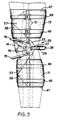
- the strut 25 has an arcuate section 27 which extends behind the knee joint 1 through the popliteal area 29 (see Figure 5) and terminates in enlarged terminal portions 31 and 33 adjacent, but spaced from the lateral and medial sides, respectively, of the joint 1. If desired, the arcuate section 27 can be covered by a soft resilient sleeve 28.
- An inferior lateral rigid elongated support member 35 is pivotally connected to the lateral terminal portion 31 of the rigid posterior strut 25 at a first pivot point by a pivot pin 37 and extends down along the lateral side of the leg 13.
- a superior medial rigid elongated support member 39 is pivotally connected to the terminal portion 33 of the rigid posterior strut 25 at a second pivot point by pivot pin 41, and extends upward medially along the thigh 7.
- the support members 33 and 39 are secured to the leg 13 and thigh 7 respectively by anchoring devices 43 and 45.
- the anchoring devices 43 and 45 each include a sleeve 47 of a non-slip, cushioning material, such as for instance neoprene, and a pair of straps 49 which are threaded through buckles 51 on the support member 35 and 39 and secured by VELCRO fasteners 53.
- These anchoring devices 43 and 45 firmly secure the support members 35 and 39 to fleshy portions of the leg 13 and thigh 7, respectively, so that forces are transmitted through these support members into the large muscles of the extremity 3.
- the prophylactic brace 23 is also provided with a pair of stiff, semirigid anterior cuff members 55 and 57.
- These cuff members are generally triangular in shape with one edge 59 secured to the associated elongated support member 35 or 39, and with the opposing vertex 61 pivotally connected such as with a snap fastener 63 to a connection point on the terminal portion 31 or 33 of the rigid posterior strut 25 opposite to the terminal portion to which the associated support member 35 or 39 is secured.
- the pivots formed by the fasteners 63 are laterally aligned with the corresponding pivot points of the elongated members to which the cuffs are attached along the edge 59.
- the cuff members 55 and 57 are unsnapped and opened for applying the brace 23 to the extremity 3, and then are wrapped around in front of the thigh and leg and snapped in place.
- the torsion force generated by rotation of the thigh 7 with the foot planted is transmitted around the knee joint 1 by the rigid posterior strut 25, and through the elongated member 35 into the leg 13.
- the stiff cuff members 55 and 57 help to balance the rotational forces and to dissipate additional energy into the leg muscles.
- Anterior and posterior forces applied to the leg 13 or the thigh 7 are similarly transmitted around the knee joint 1 through the rigid posterior strut 25 with the assistance of the stiff cuff members 55 and 57.
- FIGs 3 and 4 illustrate a functional brace 65 which is not within the scope of the claimed invention, but serves to illustrate the operation of the brace in accordance with the invention as described in Fig. 1 and 2.
- the lower portion of brace 65 is shown open in Figure 3 for application to the leg.
- This functional brace 65 also includes an inferior medial rigid elongated support member 67 pivotally connected to the terminal portion 33 of the rigid posterior strut 25 at a pivot point coaxial with the snap fastener 63.
- the functional brace 65 also includes a superior lateral support member 69 which is pivotally connected to the lateral terminal portion 31 of the strut 25 at a pivot point coaxial with the snap fastener 63, and is secured to the thigh by the straps 49.
- the functional brace 65 also includes, in addition to the generally triangularly shaped anterior cuff members 55 and 57, posterior, semicylindrical stiff cuff members 71 and 73 which extend between the respective medial and lateral support members extending along the sides of the leg 13 and thigh 7, respectively.
- the brace 65 includes additional stiff, semirigid anterior, generally triangular, cuff member 56, secured to elongated member 67 and connected by a snap fastener 63 to terminal portion 31, and cuff member 58, secured to elongated member 69 and connected by snap fastener 63 to terminal portion 33.
- additional cuffs 56 and 58 criss-cross with the cuffs 55 and 57 anterior to the leg and thigh, respectively.
- FIGs 5 and 6 are side views of the brace shown in Fig. 3 and 4, not being within the scope of the invention claimed, but useful in explaining the operation of the claimed brace.
- the rigid posterior strut 25 With the leg extended as shown in Figure 5, the rigid posterior strut 25 extends substantially horizontally, rearward into the popliteal area 29 behind the knee joint 1.
- the fleshy posterior portions of the leg (the calf) and thigh reposition the rigid posterior strut 25.
- This repositioning rotates the terminal portions 31 and 33 so that the pivot points at which the inferior and superior support members are attached are rotated to accommodate for the femoral rollback which is illustrated in Figure 6.
- the brace is automatically positioned by the natural movement of the leg, thus eliminating the need for complex joint mechanisms which are sometimes ineffective because of slippage of the brace during flexion and extension.
- Figures 5 and 6 also illustrates that one or two anterior struts 76 can be secured to the terminal portions 31 and 33 for protecting the knee joint 1 from forces acting frontally or posterior forces forcing the tibia forward.
- the forces generated by such action are transmitted through the strut 25 to the elongated support members for dissipation in the major muscles in the leg and thigh.
- the anterior struts 76 form with the posterior strut 25 a rigid support completely surrounding the knee joint and through which forces applied to the limb are transmitted around the knee joint.
- the terminal portions 31 and 33 of the rigid posterior strut 25 also serve as reference or attachment points for other devices, such as for instance, a patella stabilizer 74 as shown in Figures 5 and 6.
- the hinges formed by the terminal portions 31 and 33 of the rigid posterior strut 25 and the elongated support members can be configured to limit movement of the joint for functional or rehabilitative applications.
- a cam 75 has a vertical edge 77 which is engaged by the pivoting elongated support means such as 39 and 67 to limit extension of the joint, and biased shoulders 79 which restrict rotation of the elongated members to limit flexion of the joint.
- a pin 81 may be inserted in one of a number of holes 83 to limit extension of the knee joint to less than full extension.
- a pin 85 may be inserted in a selected hole 87 to restrict flexion.
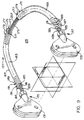
- FIG 9 illustrates in detail a modified form 125 of the rigid posterior strut 25 which is adjustable.
- the strut 125 comprises an arcuate member 127 and terminal member 131 and 133 which are secured to the arcuate member 127 by mounting members 135 and 137 respectively.
- the arcuate member 127 has a longitudinal axis 165 and is composed of two halves 167 and 169, each of which is substantially a 90° sector or a circle. Confronting ends of the halves 167 and 169 have longitudinal bores 171. An elongated piece in the form of a pin 173 telescopes into the bores 171.
- Each of the halves 167 and 169 has a slit 175 extending the length of the bore 171. Confronting radial flanges 177 along either side of the slits 175 are drawn together by screws 179 to form clamps which secure the ends of the pin 173 in the bores 171 in a fixed position.
- the free ends 181 and 183 of the halves 167 and 169, respectively, have longitudinal bores 185. Slots 187 through the walls or the arcuate members extend a substantial length along the bores 185. Confronting radial flanges 189 on either side of the slots 187 are drawn together by additional screws 191 to form clamps for securing the mounting members 135 and 137 to the arcuate member 127 as will be seen.
- the mounting members 135 and 137 each have an elongated member in the form of a stem 193 which telescopes into the bore 185 in one of the halves 167 and 169 of the arcuate member 127 and is secured in a fixed position by the clamps formed by the flanges 189 and screws 191.
- the terminal members 131 and 133 are secured to the mounting members 135 and 137, respectively, by adjustable attachments on the mounting members, preferably in the form of ball and socket connectors 195.
- these connectors 195 include balls 197 on the ends of the mounting members 135 and 137.
- Bosses 199 on the rear edges of the terminal members 131 and 133 have rearwardly facing bores with spherical bottoms 201 which define the sockets for the balls 197.
- Lock nuts 203 which thread onto the outer surface of the bosses 199 clamp an annular ring 205 with a spherical inner surface against the ball 197 to lock the terminal members 131 and 133 in fixed positions relative to the mounting members 135 and 137.
- the adjustable rigid posterior strut 125 of the invention offers great flexibility in the adjustment of the brace.
- the adjustable connection between the two halves 167 and 169 of the arcuate member 127 of the posterior strut 125 allows adjustment of the lateral/medial distance between the terminal members 131 and 133 by loosening the screws 179, sliding the stem 173 in the bores 171, and then fixing the two halves in this position by tightening the screws 179.
- Adjustment of the position of the terminal members 131 and 133 relative to each other in the sagittal plane can be made by again loosening the screws 179 and rotating the halves 167 and 169 about the stem 173 to a desired position and then retightening the screws 179.
- the stem 173, and the bores 171 are fluted as at 207 to aid in fixing the angular position of the two halves 167 and 169.
- the strut 125 may be adjusted in the anterior/posterior direction through loosening of the screw 191 and sliding the stems 193 of the mounting members 135 and 137 inward or outward in the bores 185 in the ends 181 and 183 of the arcuate halves 167 and 169, and then retightening the screws 191.
- the terminal members 131 and 133 can be rotated in the coronal plane to a desired fixed position relative to the arcuate member 127.
- the stems 193 and bores 185 can be fluted as at 209 to lock the mounting members 135 and 137 in fixed positions relative to the arcuate members 127 with less torque required on the screws 191.
- the ball and socket connectors 195 permit adjustment of the terminal members 131 and 133 in all three planes about the superior/inferior, medial/lateral and anterior/posterior axes relative to the mounting members 135 and 137.
- Figure 11 illustrates a mechanism for adjustment of the anterior cuffs 57 which may be necessitated by adjustments, especially large adjustments, to the posterior strut 125.
- a pin 211 forms a fixed pivot for attaching the cuff member 57 to the elongated support member 39.
- Fasteners in the form of screws 213 extend through arcuate slot 215, which are generally transverse to the edge 59 of the cuff and spaced above and below the pivot pin 211.
- the screws 213, which are threaded into the elongated support member 39, are loosened to adjust the angular position of the cuff member 57 to align the vertex 61 with the fastener 63 on terminal member.
- the adjustable rigid posterior strut 125 serves as the central element to which the other elements or the brace 123 are connected, either directly or indirectly, the various adjustments made to the posterior strut 125 set the position of the other elements.
- the versatility of the adjustable knee brace in accordance with the invention allows an off the shelf brace to be used for patients with extremities of various sizes and shapes. Only a very few, perhaps two or three, sizes of brace need be stocked, as those stocked parts can be assembled and adjusted to cover a full range of sizes. Furthermore, the versatility of the adjustable brace allows it to be customized for the invariable deviations from the ideal knee joint and for a large range of deformities caused by disease or injury. Furthermore, the brace can be periodically adjusted during use to accommodate for changes such as the growth of a child, or a reduction in swelling.
- the ajustable posterior strut 125 provides great versatility to offset the axis of rotation of the brace, as well as individually adjust the lateral to medial distance and offset the vertical axis of action of the affected hinge point to compensate for individual knee characteristics, or to provide the surgeon/physiotherapist a means for adjusting for abnormal knees; for either improved brace fit; optimizing the brace function/action for individual patients; or compensating for, or controlling specific motions or actions.
Landscapes
- Health & Medical Sciences (AREA)
- Nursing (AREA)
- Orthopedic Medicine & Surgery (AREA)
- Engineering & Computer Science (AREA)
- Biomedical Technology (AREA)
- Heart & Thoracic Surgery (AREA)
- Vascular Medicine (AREA)
- Life Sciences & Earth Sciences (AREA)
- Animal Behavior & Ethology (AREA)
- General Health & Medical Sciences (AREA)
- Public Health (AREA)
- Veterinary Medicine (AREA)
- Orthopedics, Nursing, And Contraception (AREA)
- Prostheses (AREA)
Claims (8)
- Eine Stütze (23) für ein Kniegelenk (1), das Oberschenkel (7) und Unterschenkelgliedmaßenteile (13) verbindet, wobei die Stütze umfaßt:erste und zweite steife Stütz- bzw. Tragglieder (39, 35), die sich nur an einer Seite des Oberschenkels bzw. an einer Seite des Unterschenkels erstrecken, wobei eine dieser Seiten medial und die andere Seite lateral ist;erste Verankerungsmittel (45), die das erste steife Tragglied (39) an dem Oberschenkel (7) entlang einem fleischigen bzw. muskulösen Abschnitt dieser einen Seite des Oberschenkels befestigen bzw. sicherm, wobei ein unteres Ende des ersten steifen Traggliedes benachbart, aber beabstandet von einer ersten Seite des Kniegelenks ist;zweite Verankerungsmittel (43), die das zweite steife Tragglied (35) an dem Unterschenkel (13) sichern entlang einem fleischigen bzw. muskulösen Abschnitt der einen Seite des Unterschenkels, wobei ein oberes Ende des zweiten steifen Traggliedes benachbart, aber beabstandet von einer zweiten Seite des Kniegelenkes ist; undeine steife bzw. starre hintere Strebe (25) mit einem ersten End- bzw. Anschlußabschnitt (33), der schwenkbar verbunden ist an einem ersten Schwenk- bzw. Drehpunkt (41) mit dem unteren Ende des ersten steifen Traggliedes (39) und nach innen beabstandet ist von der ersten Seite des Kniegelenkes (1), einen zweiten End- bzw. Anschlußabschnitt (31), der schwenkbar verbunden ist an einem zweiten Schwenk- bzw. Drehpunkt (37) mit dem oberen Ende des zweiten steifen Traggliedes (35) und nach außen beabstandet ist von der zweiten Seite des Kniegelenkes (1) und einen steifen bogenförmigen Abschnitt (27), der sich zwischen den Anschlußabschnitten durch eine Kniekehle (29) hinter dem Kniegelenk erstreckt, wobei die steife hintere Strebe (25) zwischen dem Oberschenkel und dem Unterschenkel geklemmt ist, um die ersten und zweiten Schwenk- bzw. Drehpunkte bei Beugung des Kniegelenks zu positionieren.
- Die Stütze nach Anspruch 1 umfassend:ein erstes steifes vorderes Manschettenglied (57), das an dem ersten steifen Tragglied (39) gesichert bzw. befestigt ist und sich vor dem Oberschenkel (7) herumerstreckt und drehbar mit dem zweiten Anschlußabschnitt (31) der steifen hinteren Strebe (25) verbunden ist; undein zweites steifes vorderes Manschettenglied (55), das an dem zweiten steifen Tragglied (35) gesichert bzw. befestigt ist und sich vor dem Unterschenkel (13) herumerstreckt und schwenk- bzw. drehbar mit dem ersten Anschlußabschnitt (33) der steifen hinteren Strebe (25) verbunden ist.
- Kniestütze nach Anspruch 2, bei welcher die ersten und zweiten steifen vorderen Manschettenglieder (57, 55) jeweils im allgemeinen dreieckige Glieder sind mit einer Seitenkante (59) und einem Scheitel bzw. einer Ecke (61) gegenüberliegend der Seitenkante, wobei die Seitenkante (59) des ersten steifen Manschettengliedes (57) entlang dem ersten steifen Tragglied (39) befestigt ist und die Ecke des ersten steifen Manschettengliedes schwenk- bzw. drehbar an dem zweiten Anschlußabschnitt (31) der steifen hinteren Strebe (25) befestigt ist an einem Verbindungspunkt (63), der lateral ausgerichtet ist mit dem ersten Schwenk- bzw. Drehpunkt (41) an dem ersten Anschlußabschnitt (33) der steifen hinteren Strebe (25) und die Seitenkante (59) des zweiten steifen Manschettengliedes (55) entlang dem zweiten steifen Tragglied (31) befestigt ist und die Ecke (61) das zweiten steifen Manschettengliedes schwenk- bzw. drehbar an dem ersten Anschlußabschnitt (33) mit der steifen hinteren Strebe befestigt ist an einem Verbindungspunkt (63), der lateral ausgerichtet ist mit dem zweiten Schwenk- bzw. Drehpunkt (37) an dem zweiten Anschlußabschnitt (31) der steifen hinteren Strebe.
- Kniestütze nach einem der Ansprüche 1 bis 3, bei welcher die steife hintere Strebe (125) Einrichtungen (137, 135) umfaßt, die die Anschlußabschnitte (133, 131) der steifen hinteren Strebe einstellbar fixieren in ausgewählten Positionen relativ zu dem steifen bogenförmigen Abschnitt (127).
- Kniestütze nach Anspruch 1, bei welcher die steife hintere Strebe (125) einstellbar ist und aufweist:ein steifes bogenförmiges Glied (127) mit ersten und zweiten Enden (183, 181) und einer Längsachse (165); erste und zweite Anschlußglieder (133, 131) mit Schwenk- bzw. Drehverbindungen für die steifen Tragglieder (39, 35); und erste und zweite einstellbare Montageglieder (137, 135), die die ersten und zweiten Anschlußglieder einstellbar an den ersten bzw. zweiten Enden des bogenförmigen Gliedes in ausgewählten Positionen relativ zu dem bogenförmigen Glied fixieren.
- Kniestütze nach Anspruch 5, bei welcher die ersten und zweiten Montageglieder (137, 135) gestreckte Glieder (193) umfassen, die axial verlängerbar sind bezüglich der ersten und zweiten Enden (183, 181) des bogenförmigen Gliedes (127) und schwenk- bzw. drehbar sind bezüglich der Längsachse (165) des bogenförmigen Gliedes und erste und zweite Sicherungs- bzw. Befestigungseinrichtungen (189, 191), welche die gestreckten Glieder in auswählbaren axialen und rotatorischen Positionen relativ zu den ersten bzw. zweiten Enden des bogenförmigen Gliedes fest sichern.
- Kniestütze nach Anspruch 6, bei welcher die ersten und zweiten Montageglieder (137, 135) weiter erste und zweite einstellbare Anbringungseinrichtungen (195) umfassen, die die ersten und zweiten Anschlußglieder (133, 131) in auswählbaren Positionen relativ zu den ersten und zweiten Montagegliedern fixieren.
- Kniestütze nach einem der Ansprüche 5 bis 7, bei welcher das bogenförmige Glied (127) erste und zweite Hälften (169 167) aufweist, die um die Längsachse (165) in auswählbaren Winkelpositionen bezüglich einander schwenk- bzw. drehbar sind und entlang der Längsachse in ausgewählten axialen Positionen relativ zueinander axial verlängerbar sind, und Verbindungseinrichtungen (173, 177, 179), die die ersten und zweiten Hälften fest miteinander verbinden in einer ausgewählten Winkel- und einer ausgewählten axialen Position.
Priority Applications (1)
| Application Number | Priority Date | Filing Date | Title |
|---|---|---|---|
| AT92914154T ATE170073T1 (de) | 1992-05-11 | 1992-05-11 | Kniegelenksorthese |
Applications Claiming Priority (1)
| Application Number | Priority Date | Filing Date | Title |
|---|---|---|---|
| PCT/US1992/003903 WO1993022992A1 (en) | 1992-05-11 | 1992-05-11 | Knee brace with posterior strut |
Publications (3)
| Publication Number | Publication Date |
|---|---|
| EP0639960A1 EP0639960A1 (de) | 1995-03-01 |
| EP0639960A4 EP0639960A4 (de) | 1995-04-19 |
| EP0639960B1 true EP0639960B1 (de) | 1998-08-26 |
Family
ID=22231061
Family Applications (1)
| Application Number | Title | Priority Date | Filing Date |
|---|---|---|---|
| EP92914154A Expired - Lifetime EP0639960B1 (de) | 1992-05-11 | 1992-05-11 | Kniegelenksorthese |
Country Status (4)
| Country | Link |
|---|---|
| EP (1) | EP0639960B1 (de) |
| AU (1) | AU2225492A (de) |
| DE (1) | DE69226786D1 (de) |
| WO (1) | WO1993022992A1 (de) |
Families Citing this family (8)
| Publication number | Priority date | Publication date | Assignee | Title |
|---|---|---|---|---|
| ITVR20030128A1 (it) * | 2003-10-31 | 2005-05-01 | Fgp Srl | Snodo per ginocchiera ad uso ortopedico, provvisto di |
| WO2008061300A1 (en) * | 2006-11-20 | 2008-05-29 | Pod I.P. Pty Ltd | Knee brace with self-tracking patella guard |
| US9925082B2 (en) | 2012-03-20 | 2018-03-27 | Ossur Hf | Orthopedic device |
| US10617549B2 (en) | 2016-04-04 | 2020-04-14 | Ossur Iceland Ehf | Orthopedic device |
| USD813089S1 (en) | 2016-11-08 | 2018-03-20 | Ossur Iceland Ehf | D-ring |
| USD835289S1 (en) | 2016-11-08 | 2018-12-04 | Ossur Iceland Ehf | Orthopedic device |
| US10682785B1 (en) | 2017-01-24 | 2020-06-16 | William Stuart | Method for producing a negative cast for a brace with corrective forces to control PLC deficiencies |
| CN109310563B (zh) * | 2017-03-07 | 2022-12-23 | 佐喜真义肢股份有限公司 | 膝肘关节辅助装置 |
Family Cites Families (7)
| Publication number | Priority date | Publication date | Assignee | Title |
|---|---|---|---|---|
| US3026869A (en) * | 1957-03-12 | 1962-03-27 | Paramount Textile Mach Co | Orthopedic leg brace |
| US4088130A (en) * | 1977-05-16 | 1978-05-09 | Surgical Appliance Industries, Inc. | Hinge for knee brace |
| FR2486388B1 (fr) * | 1980-07-09 | 1986-07-25 | Lecante Pierre | Prothese pour le maintien des parties articulees des membres superieurs et inferieurs |
| FR2552660B1 (fr) * | 1983-09-29 | 1988-10-14 | Delbos Jean | Appareillage d'assistance de l'articulation du genou |
| FR2581859B1 (fr) * | 1985-04-11 | 1995-10-20 | Lecante Pierre | Orthese pour le maintien de l'articulation du genou |
| GB2215213B (en) * | 1988-02-02 | 1991-11-13 | Protectair Ltd | Knee brace |
| JPH01214380A (ja) * | 1988-02-24 | 1989-08-28 | K & K Kogyo Kk | 脚部のプロテクタ |
-
1992
- 1992-05-11 DE DE69226786T patent/DE69226786D1/de not_active Expired - Lifetime
- 1992-05-11 WO PCT/US1992/003903 patent/WO1993022992A1/en not_active Ceased
- 1992-05-11 EP EP92914154A patent/EP0639960B1/de not_active Expired - Lifetime
- 1992-05-11 AU AU22254/92A patent/AU2225492A/en not_active Abandoned
Also Published As
| Publication number | Publication date |
|---|---|
| WO1993022992A1 (en) | 1993-11-25 |
| EP0639960A1 (de) | 1995-03-01 |
| AU2225492A (en) | 1993-12-13 |
| EP0639960A4 (de) | 1995-04-19 |
| DE69226786D1 (de) | 1998-10-01 |
Similar Documents
| Publication | Publication Date | Title |
|---|---|---|
| US5133341A (en) | Knee brace with posterior strut | |
| US5267946A (en) | Knee brace with adjustable rigid posterior strut | |
| US5277697A (en) | Patella-femoral brace | |
| US5496263A (en) | Ankle stabilization system | |
| US5383845A (en) | Hinged orthopedic brace having compliant support components | |
| US7534219B2 (en) | Orthopaedic brace assembly | |
| US5658241A (en) | Multi-functional dynamic splint | |
| EP0432303B1 (de) | Orthese | |
| US4733656A (en) | Knee stabilizer | |
| US7850632B2 (en) | Knee brace having an adaptable thigh pad | |
| US8202239B2 (en) | Ankle derotation and subtalar stabilization orthosis | |
| US20230404785A1 (en) | Cable brace system | |
| US8343083B1 (en) | Auto-flex knee brace | |
| WO1996004870A1 (en) | Medial collateral ligament brace | |
| WO2005087149A1 (en) | Patella femoral brace | |
| US4790299A (en) | Knee stabilizer | |
| EP0639960B1 (de) | Kniegelenksorthese | |
| EP1861051B1 (de) | Verstellbare knieschiene | |
| AU2026202111A1 (en) | Cable brace system | |
| CN113939253B (zh) | 线缆膝部支具系统 | |
| EP0551285A1 (de) | Patella-femurschiene | |
| CA2186227C (en) | Multi-functional dynamic splint | |
| EP0173161B1 (de) | Vielachsig bewegungsgesteuerte Knieausrichtung | |
| US20030135144A1 (en) | Leg brace support structure | |
| CA2263040C (en) | Multi-functional dynamic splint |
Legal Events
| Date | Code | Title | Description |
|---|---|---|---|
| PUAI | Public reference made under article 153(3) epc to a published international application that has entered the european phase |
Free format text: ORIGINAL CODE: 0009012 |
|
| 17P | Request for examination filed |
Effective date: 19941212 |
|
| AK | Designated contracting states |
Kind code of ref document: A1 Designated state(s): AT BE CH DE DK ES FR GB GR IT LI LU MC NL SE |
|
| A4 | Supplementary search report drawn up and despatched | ||
| AK | Designated contracting states |
Kind code of ref document: A4 Designated state(s): AT BE CH DE DK ES FR GB GR IT LI LU MC NL SE |
|
| 17Q | First examination report despatched |
Effective date: 19960503 |
|
| GRAG | Despatch of communication of intention to grant |
Free format text: ORIGINAL CODE: EPIDOS AGRA |
|
| RAP3 | Party data changed (applicant data changed or rights of an application transferred) |
Owner name: FRIED, JEFFREY A. Owner name: SINGER, SAMUEL |
|
| GRAG | Despatch of communication of intention to grant |
Free format text: ORIGINAL CODE: EPIDOS AGRA |
|
| GRAH | Despatch of communication of intention to grant a patent |
Free format text: ORIGINAL CODE: EPIDOS IGRA |
|
| GRAH | Despatch of communication of intention to grant a patent |
Free format text: ORIGINAL CODE: EPIDOS IGRA |
|
| GRAA | (expected) grant |
Free format text: ORIGINAL CODE: 0009210 |
|
| AK | Designated contracting states |
Kind code of ref document: B1 Designated state(s): AT BE CH DE DK ES FR GB GR IT LI LU MC NL SE |
|
| PG25 | Lapsed in a contracting state [announced via postgrant information from national office to epo] |
Ref country code: NL Free format text: LAPSE BECAUSE OF FAILURE TO SUBMIT A TRANSLATION OF THE DESCRIPTION OR TO PAY THE FEE WITHIN THE PRESCRIBED TIME-LIMIT Effective date: 19980826 Ref country code: LI Free format text: LAPSE BECAUSE OF FAILURE TO SUBMIT A TRANSLATION OF THE DESCRIPTION OR TO PAY THE FEE WITHIN THE PRESCRIBED TIME-LIMIT Effective date: 19980826 Ref country code: IT Free format text: LAPSE BECAUSE OF FAILURE TO SUBMIT A TRANSLATION OF THE DESCRIPTION OR TO PAY THE FEE WITHIN THE PRESCRIBED TIME-LIMIT;WARNING: LAPSES OF ITALIAN PATENTS WITH EFFECTIVE DATE BEFORE 2007 MAY HAVE OCCURRED AT ANY TIME BEFORE 2007. THE CORRECT EFFECTIVE DATE MAY BE DIFFERENT FROM THE ONE RECORDED. Effective date: 19980826 Ref country code: GR Free format text: LAPSE BECAUSE OF NON-PAYMENT OF DUE FEES Effective date: 19980826 Ref country code: FR Free format text: LAPSE BECAUSE OF FAILURE TO SUBMIT A TRANSLATION OF THE DESCRIPTION OR TO PAY THE FEE WITHIN THE PRESCRIBED TIME-LIMIT Effective date: 19980826 Ref country code: ES Free format text: THE PATENT HAS BEEN ANNULLED BY A DECISION OF A NATIONAL AUTHORITY Effective date: 19980826 Ref country code: CH Free format text: LAPSE BECAUSE OF FAILURE TO SUBMIT A TRANSLATION OF THE DESCRIPTION OR TO PAY THE FEE WITHIN THE PRESCRIBED TIME-LIMIT Effective date: 19980826 Ref country code: BE Free format text: LAPSE BECAUSE OF FAILURE TO SUBMIT A TRANSLATION OF THE DESCRIPTION OR TO PAY THE FEE WITHIN THE PRESCRIBED TIME-LIMIT Effective date: 19980826 Ref country code: AT Free format text: LAPSE BECAUSE OF FAILURE TO SUBMIT A TRANSLATION OF THE DESCRIPTION OR TO PAY THE FEE WITHIN THE PRESCRIBED TIME-LIMIT Effective date: 19980826 |
|
| REF | Corresponds to: |
Ref document number: 170073 Country of ref document: AT Date of ref document: 19980915 Kind code of ref document: T |
|
| REG | Reference to a national code |
Ref country code: CH Ref legal event code: EP |
|
| REF | Corresponds to: |
Ref document number: 69226786 Country of ref document: DE Date of ref document: 19981001 |
|
| PG25 | Lapsed in a contracting state [announced via postgrant information from national office to epo] |
Ref country code: SE Free format text: LAPSE BECAUSE OF FAILURE TO SUBMIT A TRANSLATION OF THE DESCRIPTION OR TO PAY THE FEE WITHIN THE PRESCRIBED TIME-LIMIT Effective date: 19981126 Ref country code: DK Free format text: LAPSE BECAUSE OF FAILURE TO SUBMIT A TRANSLATION OF THE DESCRIPTION OR TO PAY THE FEE WITHIN THE PRESCRIBED TIME-LIMIT Effective date: 19981126 |
|
| PG25 | Lapsed in a contracting state [announced via postgrant information from national office to epo] |
Ref country code: DE Free format text: LAPSE BECAUSE OF FAILURE TO SUBMIT A TRANSLATION OF THE DESCRIPTION OR TO PAY THE FEE WITHIN THE PRESCRIBED TIME-LIMIT Effective date: 19981127 |
|
| EN | Fr: translation not filed | ||
| NLV1 | Nl: lapsed or annulled due to failure to fulfill the requirements of art. 29p and 29m of the patents act | ||
| REG | Reference to a national code |
Ref country code: CH Ref legal event code: PL |
|
| PG25 | Lapsed in a contracting state [announced via postgrant information from national office to epo] |
Ref country code: LU Free format text: LAPSE BECAUSE OF NON-PAYMENT OF DUE FEES Effective date: 19990511 |
|
| PGFP | Annual fee paid to national office [announced via postgrant information from national office to epo] |
Ref country code: GB Payment date: 19990512 Year of fee payment: 8 |
|
| PLBE | No opposition filed within time limit |
Free format text: ORIGINAL CODE: 0009261 |
|
| STAA | Information on the status of an ep patent application or granted ep patent |
Free format text: STATUS: NO OPPOSITION FILED WITHIN TIME LIMIT |
|
| 26N | No opposition filed | ||
| PG25 | Lapsed in a contracting state [announced via postgrant information from national office to epo] |
Ref country code: MC Free format text: LAPSE BECAUSE OF NON-PAYMENT OF DUE FEES Effective date: 19991130 |
|
| PG25 | Lapsed in a contracting state [announced via postgrant information from national office to epo] |
Ref country code: GB Free format text: LAPSE BECAUSE OF NON-PAYMENT OF DUE FEES Effective date: 20000511 |
|
| GBPC | Gb: european patent ceased through non-payment of renewal fee |
Effective date: 20000511 |