EP0640045B1 - Dachgepäckkoffer - Google Patents
Dachgepäckkoffer Download PDFInfo
- Publication number
- EP0640045B1 EP0640045B1 EP93910532A EP93910532A EP0640045B1 EP 0640045 B1 EP0640045 B1 EP 0640045B1 EP 93910532 A EP93910532 A EP 93910532A EP 93910532 A EP93910532 A EP 93910532A EP 0640045 B1 EP0640045 B1 EP 0640045B1
- Authority
- EP
- European Patent Office
- Prior art keywords
- box
- parts
- lid
- halves
- deposit container
- Prior art date
- Legal status (The legal status is an assumption and is not a legal conclusion. Google has not performed a legal analysis and makes no representation as to the accuracy of the status listed.)
- Expired - Lifetime
Links
- 238000005304 joining Methods 0.000 claims description 17
- 238000006073 displacement reaction Methods 0.000 claims 1
- 239000004033 plastic Substances 0.000 description 5
- 238000000034 method Methods 0.000 description 4
- 239000000463 material Substances 0.000 description 3
- XLYOFNOQVPJJNP-UHFFFAOYSA-N water Substances O XLYOFNOQVPJJNP-UHFFFAOYSA-N 0.000 description 3
- 230000006378 damage Effects 0.000 description 2
- 238000002347 injection Methods 0.000 description 2
- 239000007924 injection Substances 0.000 description 2
- 238000003860 storage Methods 0.000 description 2
- 239000004743 Polypropylene Substances 0.000 description 1
- 230000015572 biosynthetic process Effects 0.000 description 1
- 230000000052 comparative effect Effects 0.000 description 1
- 230000008878 coupling Effects 0.000 description 1
- 238000010168 coupling process Methods 0.000 description 1
- 238000005859 coupling reaction Methods 0.000 description 1
- 239000000446 fuel Substances 0.000 description 1
- 239000004922 lacquer Substances 0.000 description 1
- 238000004519 manufacturing process Methods 0.000 description 1
- -1 polypropylene Polymers 0.000 description 1
- 229920001155 polypropylene Polymers 0.000 description 1
- 238000007666 vacuum forming Methods 0.000 description 1
Images


Classifications
-
- B—PERFORMING OPERATIONS; TRANSPORTING
- B60—VEHICLES IN GENERAL
- B60R—VEHICLES, VEHICLE FITTINGS, OR VEHICLE PARTS, NOT OTHERWISE PROVIDED FOR
- B60R9/00—Supplementary fittings on vehicle exterior for carrying loads, e.g. luggage, sports gear or the like
- B60R9/04—Carriers associated with vehicle roof
- B60R9/055—Enclosure-type carriers, e.g. containers, boxes
-
- F—MECHANICAL ENGINEERING; LIGHTING; HEATING; WEAPONS; BLASTING
- F16—ENGINEERING ELEMENTS AND UNITS; GENERAL MEASURES FOR PRODUCING AND MAINTAINING EFFECTIVE FUNCTIONING OF MACHINES OR INSTALLATIONS; THERMAL INSULATION IN GENERAL
- F16B—DEVICES FOR FASTENING OR SECURING CONSTRUCTIONAL ELEMENTS OR MACHINE PARTS TOGETHER, e.g. NAILS, BOLTS, CIRCLIPS, CLAMPS, CLIPS OR WEDGES; JOINTS OR JOINTING
- F16B2200/00—Constructional details of connections not covered for in other groups of this subclass
- F16B2200/50—Flanged connections
Definitions
- the present invention generally relates to a deposit container of the type which is nowadays commonly used as a motor car roof-box, a ski box, or as a container for any kinds of goods.
- roof boxes of the said type There exist many various types and sizes of roof boxes of the said type. Most roof boxes are relatively long, often between 2 and 2.5 meters long, and they have generally been made as a bottom box part which can be clamped to a couple of roof racks, load racks or any other mounting means at the roof of a motor car, and which bottom box part has a rotatably connected lid box part, which is usually rotatably connected at the front edge or the rear edge of the bottom box part, but which may alternatively be rotatably connected at any of the long sides of the car roof box.
- a deposit container of the above mentioned type also is useful as a load container for boats, ski sleighs and for many other purposes.
- a problem in connection to roof boxes of the priorly known type is that said boxes are very bulky, and that the boxes often must be hoisted up to the garage ceiling by means of blocks and pulleys when the roof boxes are removed from the car or the bus, or from the boat etc. It is also possible to put the roof box down standing on its rear end and to strap the box e.g. to a wall so that the box does not tilt over and damages objects or persons standing in the vicinity the the roof box. Many car drivers have no garage and can often not have the roof box standing or hanging in his home, and in such cases it may be necessary to let the roof box remain on the motor car all the year. This leads to unnecessarily increased fuel consumption upon driving the car, there appear problems when the car is to be washed, wind noice, destruction of the lacquer etc.
- roof boxes Upon sale in a store such roof boxes also occupy so large space that they are generally exposed in special storage stands with several boxes placed above each other. Such storage stands are large, bulky and expensive.
- the known roof boxes mostly are manufactured by a vacuum forming process of a suitable plastic material generally using large plastic plates.
- the toos for vacuum formation are large and are difficult to handle, and the plastic plate material from which the the roof box bottom and the roof box lid is press formed is expensive.
- the object of the invention therefore is to suggest a deposit container which can be used for many different purposes, for instance as a roof box for a motor car, as a ski box, as a deposit box for boats, buses, caravans, motor homes, snow sleighs etc,
- the transport container or the roof box according to the invention is defined in accompanying Claim 1. Following particular features are to be mentioned
- the bottom box part and the the lid box part are similar to each other and that both said box parts are composed of two identical box part halves, each of said two box part halves being manufactured in one and the same injection mould machine, whereby the roof box is symmetrical about a transverse vertical plane.
- Both pieces of the bottom box part and of the the lid box part respectively are, at a transversal interconnection plane thereof, formed with means for joining said parts to form an interconnected unit.
- Said means may for instance by a U-shaped groove extending over half the width of the box part connection plane, and a rib corresponding to said U-shaped groove and extending of the other half of the width of the box part connection plane.
- the halves are moved together in a position rotated along a longitudinal axis about 90° in relation to each other, whereafter said halves are rotated back about said longitudinal axis to form a common bottom box or lid box.
- the rib of one of the box part halves is being locked in the U-shaped groove in the other box part half, and vice versa.
- the box part halves are locked in their interconnected positions by means of a couple or simple and easily mountable and dismountable spring pins or a similar means which are introduced into fitting bores of the U-groove and the ribs respectively thereby preventing the bottom and lid part halves to rotate in relation to each other.
- the joining edges may be flat and even and preferably are formed with cooperating bores for the pins and the screw-nut means resp.
- roof bottom box part or the roof lid part hinges are inroduced and are secured in standard sockets, and at the opposite longitudinal side locks are introduced in the same type of standard sockets and are secured by means of simple pins or similar means, whereupon a bottom box part is interconnected to a lid box part. Thereafter the roof box is ready for direct use or for being mounted on roof racks or on any other mounting means at the roof of a car or a bus, on the deck of a boat or in any other place.
- a unit of four interconnected roof boxes is known from DE-A-3 546 220.
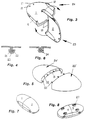
- figure 1 shows, in an exploded view perspectively obliquely from above, a lid for a deposit container or a roof box according to the invention, and figure 2 correspondingly shows a bottom box part of the same deposit container.
- Figure 3 diagrammatically illustrates the interconnection of the two halves of a first embodiment of a roof box
- figure 4 is a cross section view of a spring pin securing means for said two box halves.
- Figure 5 diagrammatically illustrates the joining principle for a second embodiment of a roof box
- figure 6 shows, like in figure 4, a method of securing the two box halves in said second embodiment.
- Figure 7 shows a ready mounted roof box, seen obliquely from above, and figure 8 shows the same roof box obliquely from underneath.
- Figure 9 shows a bottom box part of an alternative embodiment of a roof box
- figure 10 shows a method of securing the roof box halves to each other by means of an integral locking means.
- Figure 11 shows a sale-packed or dismounted roof box according to the invention in its package
- figure 12 shows, compared thereto, a roof box of a priorily known type and of substantially the same size as the roof box which is shown dismounted in figure 11.
- the deposit container or roof box comprises four main parts, namely two identical lid box halves 1 and 2 and two identical bottom box halves 3 and 4. Said parts are mainly elliptical both in the horizontal direction and the vertical direction, so that the ready roof box gets a low air flow resistance and provides very little wind noice when transported at high speeds.
- the two longitudinal sides 5 and 6 resp. are flattened along a part of the roof box, and at the exterior side of said flattened sides there are standad sockets or fittings 7 for hinges 8 or locks 9.
- said standard fittings are shown in the form of two cooperating angle bars which, in common, form a vertical slot in which any desired means can be introduced.
- the hinges 8 are formed so that they simply are let down in the fittings 7 and are secured in this position for instance by means of simple pins which are introduced in bores 10 in the hinge 8 and bores 11 in the roof box sides 5 and 6.
- the locks 9 are formed so that they can be secured in identical bores 11 of the roof box sides 5 and 6.
- the mounted hinges 8 and locks 9 are covered by bowl-formed casings 12 having barb-like securing pins 13 arranged to be introduced in corresponding bores 14 of the roof box sides 5 and 6.
- the lid box parts 1 and 2 and the bottom box parts 3 and 4 respectively are identical and can be manufactured in one and the same press-cast mould. As shown in figures 1 and 2 each of the parts 1, 2, 3 and 4 is formed like a semi-bowl having a convex upper surface and bottom surface resp. and having a curved front and rear edge resp. and a flat joining edge 18.
- the lid has a convexly upwards extending lid cup 19, and the bottom similarly has a convexly downwards extending bottom cup 20.
- each joining edge 18 has two inwardly extending joining pieces, namely a channel forming a U-shaped groove 21 extending along the edges of the sides 5 and 6 and along half the width of the lid cup 19 and the bottom cup 20 resp., and a rib 22 extending along the edges of the opposite flat sides 5 and 6 and along the other half of the width of the lid cup 19 and the bottom cup 20 resp.
- the meeting edges of the groove 21 and the rib 22 are slightly bevelled to form a V-groove for making it possible to join the two lid and bottom halves rotated 90° angle in relation to each other for interconnection of said halves to form a complete lid piece and a complete bottom piece.
- the interconnection of the lid box halves or the bottom box halves 23, 24 is made in that one 23 of said halves is rotated about 90° in relation to the other half 24; the two halves are moved together with the flat joining edges 18 thereof facing each other, so that the V-shaped grooves between the U-grooves 21 and the ribs 22 engage each other; said one lid half 23 is rotated back, whereby the rib 22 of the first half 23 engages the groove 21 of the other half 24 and vice versa.
- the common beam formed by the joining edge at the transversal center of the roof box also acts as a stiffening beam and as a rain water lock in that rain water from the lid part is drained to the sides. Eventuelly existing water in the box bottom part is drained through the V-shaped groove between the U-groove 21 and the rib 22.
- a hinge 8 is pressed down in the fittings 7 on one side of the bottom box or the lid box and is locked therein by means of a pin which is introduced through bores 10, 11 of the hinge and the bottom box and the lid box.
- a casing 12 is connected in that the barb pins 13 are introduced into bores 14of the lid and the bottom sides 5, 6.
- a lock 9 is introduced in the fitting 7 and in the bore 11 and is secured as known per se.
- a cover or casing 12 is also mounted over the lock 9.
- a gas spring 16 can be mounted between the sockets 15 of the bottom box and the lid box at one end 17 or at both ends.
- the bottom box can be formed with several feet 27 which in common form an even support surface for the container.
- the feet 27 can be formed with several through bores 28 in which a clamp yoke 29 can engage and can be screw connected for keeping the container secured to a roof rack of a motor car or to any other mounting means.
- a safety washer 30 is mounted inside each foot 27.
- the meeting edges 31 are flat and even and are formed with bores 32 in which barb-like spring pins 33 can be introduced for keeping the halves together, or it is alternatively possible to use simple screw-wingnut means 34 as shown in the cross section view in figure 6.
- the coupling means shown in figures 4 and 6 can be substituted by a pin 25' which is fixedly connected to the bottom box 3' or the lid box and which is kept in place by a spring clamp and which can snap engage the bores 26 of interengaging box halves and keep said halves locked to each other.
- a pin 25' which is fixedly connected to the bottom box 3' or the lid box and which is kept in place by a spring clamp and which can snap engage the bores 26 of interengaging box halves and keep said halves locked to each other.
- the roof box After the roof box has been used it can easily be dismounted by releasing the gas spring 16, one of the securing means for the hinge and the spring pins 26 for the box portions 1-4.
- the box portions thereafter can be placed together, partly introduced in each other, and can be stored in its package as shown in figure 11, whereby the roof box occupies a substantially less space than the bulky, priorly known roof box which is shown in figure 12 as a comparative example.
Landscapes
- Engineering & Computer Science (AREA)
- Mechanical Engineering (AREA)
- Fittings On The Vehicle Exterior For Carrying Loads, And Devices For Holding Or Mounting Articles (AREA)
- Packages (AREA)
- Closures For Containers (AREA)
- Workshop Equipment, Work Benches, Supports, Or Storage Means (AREA)
- Cartons (AREA)
- Stackable Containers (AREA)
Claims (9)
- Aufbewahrungsbehälter, der für verschiedene Zwecke nützlich ist, zum Beispiel als Autodachkoffer, als Skicontainer, als Aufbewahrungsbehälter für Boote, Schiffe, Wohnwagen, Wohnmobile, Motorschlitten, usw., und der aus mehreren kleinen Einheiten (1 - 4) zusammengesetzt ist und montierbar und demontierbar ist, dadurch gekennzeichnet,
daß der Behälter im wesentlichen aus vier Kofferbauteilen zusammengesetzt ist, nämlich zwei identischen oder fast identischen Kofferdeckelhälften (1, 2) und zwei identischen oder fast identischen Kofferbodenhälften (3, 4) mit Standardbeschlägen (7) für Scharniere (8) und Verschlüsse (9) und andere Mittel,
daß jedes der Kofferbauteile (1 - 4) mit einer flachen Verbindungskante (18) ausgebildet ist,
daß die Verbindungskante (18) Mittel (21, 22) zum schnellen und einfachen paarweisen Verbinden der Bauteile hat, um eine integrale, vollständige Deckeleinheit (1, 2) bzw. eine integrale, vollständige Bodeneinheit (3, 4) zu bilden,
daß sich die Verbindungskante (18) für die Kofferdeckelhälften (1, 2) bzw. die Kofferbodenhälften (3, 4) im fertig zusammengebauten Aufbewahrungsbehälter über eine transversale und eine vertikale Ebene erstreckt, und
daß die Kofferdeckelbauteile (1, 2) und die Kofferbodenbauteile (3, 4) in Form und Größe so ähnlich sind, daß die Bauteile, ineinander gestapelt und in diesem kompakten Zustand gelagert werden können, wenn der Aufbewahrungsbehälter demontiert ist. - Aufbewahrungsbehälter nach Anspruch 1, dadurch gekennzeichnet, daß, die Kofferdeckelhälften (1, 2) bzw. die Kofferbodenhälften (3, 4) identisch sind, und daß der Behälter symmetrisch bezüglich der transversalen und vertikalen Ebene ist.
- Aufbewahrungsbehälter nach Anspruch 2, dadurch gekennzeichnet, daß die transversale Verbindungskante (18) jedes der Bauteile (1, 2) des Kofferdeckels und jedes der Bauteile (3, 4) des Kofferbodens eine nach außen weisende U-förmige Nut (21) hat, die sich über die halbe Breite des Kofferbauteils erstreckt, und eine der U-förmigen Nut (21) entsprechende und zu dieser passende Feder (22) hat, die sich entlang der anderen Hälfte der Breite des Kofferbauteils erstreckt.
- Aufbewahrungsbehälter nach Anspruch 3, dadurch gekennzeichnet, daß die zusammenstoßenden Kanten der U-förmigen Nut (21) und der Feder (22) abgeschrägt sind, so daß sie zwischen sich eine V-förmige Nut bilden, wobei zwei gleiche Bauteile (1 - 2 bzw. 3 - 4) dadurch verbunden werden können, daß die Bauteile um etwa 90° zueinander verdreht zusammengeführt und anschließend wieder zurückgedreht werden, so daß die U-Nut (21) und die entsprechende Feder (22) ineinander fassen.
- Aufbewahrungsbehälter nach einem der Ansprüche 2 bis 4, dadurch gekennzeichnet, daß die Bauteile des Deckels bzw. die Bauteile des Bodens selbstverriegelnd gegen Relativverschiebungen in longitudinaler und transversaler Richtung sind, und daß die Bauteile gegen relative Verdrehungen mittels eines oder mehrerer einfacher Riegel (25) gesichert sind, die in Bohrungen (26) in den Verbindungskanten (18) einfassen.
- Aufbewahrungsbehälter nach Anspruch 1 und 2, dadurch gekennzeichnet, daß die Verbindungskanten (31) flach und eben sind und mit Bohrungen (32) zum Verbinden der Deckel- oder Bodenhälften mittels Widerhaken-Bolzen (33) und/oder Schrauben-Mutter-Verbindungsmitteln (34) versehen sind.
- Aufbewahrungsbehälter nach Anspruch 1, dadurch gekennzeichnet, daß die Standardbeschläge (7) mit einem Schlitz versehen sind, in den ein Scharnier (8), ein Verschluß (9) oder ein anderes Mittel nach unten hineingedrückt werden kann und z.B. mittels eines einfachen Bolzens verriegelt werden kann.
- Aufbewahrungsbehälter nach einem der vorhergehenden Ansprüche, dadurch gekennzeichnet, daß der Behälter mit lösbaren, halbkugelförmigen Abdeckungen (12) versehen ist, die zum einrastenden Verbinden über einem Scharnier (8), einem Verschluß (9) oder irgendeinem anderen, in einem gängigen Beschlag (7) eingebauten Mittel angeordnet sind.
- Aufbewahrungsbehälter nach einem der vorhergehenden Ansprüche, dadurch gekennzeichnet, daß sowohl der Kofferdeckel als auch der Kofferboden eine konvexe, schalenförmige Fläche (19, 20) und einen bogenförmigen Endabschnitt (17) hat, und daß wenigstens die Kofferbodenbauteile (3, 4) mit Füßen (27) versehen sind, die gemeinsam eine gleichmäßige Auflagefläche bilden, und daß diese Füße (27) an ihrem Boden Bohrungen (28) haben, die zum Zusammenwirken mit einem Haltebügel (29) ausgebildet sind, mittels dessen der Behälter an einem geeigneten Objekt gehaltert werden kann.
Applications Claiming Priority (3)
| Application Number | Priority Date | Filing Date | Title |
|---|---|---|---|
| SE9201565A SE470257B (sv) | 1992-05-19 | 1992-05-19 | Förvaringsbehållare av takboxtyp |
| SE9201565 | 1992-05-19 | ||
| PCT/SE1993/000429 WO1993023268A1 (en) | 1992-05-19 | 1993-05-14 | Deposit container of roof box type |
Publications (2)
| Publication Number | Publication Date |
|---|---|
| EP0640045A1 EP0640045A1 (de) | 1995-03-01 |
| EP0640045B1 true EP0640045B1 (de) | 1996-07-10 |
Family
ID=20386276
Family Applications (1)
| Application Number | Title | Priority Date | Filing Date |
|---|---|---|---|
| EP93910532A Expired - Lifetime EP0640045B1 (de) | 1992-05-19 | 1993-05-14 | Dachgepäckkoffer |
Country Status (9)
| Country | Link |
|---|---|
| US (1) | US5582313A (de) |
| EP (1) | EP0640045B1 (de) |
| JP (1) | JPH08504702A (de) |
| AT (1) | ATE140193T1 (de) |
| AU (1) | AU4099193A (de) |
| DE (1) | DE69303607T2 (de) |
| SE (1) | SE470257B (de) |
| TW (1) | TW244348B (de) |
| WO (1) | WO1993023268A1 (de) |
Families Citing this family (28)
| Publication number | Priority date | Publication date | Assignee | Title |
|---|---|---|---|---|
| DE19644527C1 (de) * | 1996-10-26 | 1998-03-26 | Daimler Benz Ag | Transportbehältersystem für ein Kraftfahrzeug |
| US5975002A (en) * | 1997-07-24 | 1999-11-02 | Triton Boat Company, L.P. | Storage system for marine craft |
| US6574911B1 (en) | 2002-01-18 | 2003-06-10 | Genmar Ip Llc | Tackle organizer |
| US6880480B2 (en) * | 2002-06-21 | 2005-04-19 | Genmar Ip Llc | Tackle organizer |
| US6918521B2 (en) * | 2003-01-28 | 2005-07-19 | Watermark Paddlesports, Inc. | Car top carrier with quick release clamping device |
| US7503470B2 (en) * | 2003-01-28 | 2009-03-17 | Yakima Products, Inc. | Car top carrier |
| US7258260B2 (en) * | 2003-08-29 | 2007-08-21 | Hurd Jonathan H | Cargo system attachable to a roof rack |
| DE102004035154B4 (de) * | 2004-07-20 | 2023-06-07 | Thule Gmbh & Co. Kg | Halterungsvorrichtung zur Befestigung eines Dachkoffers |
| US7980436B2 (en) * | 2005-07-01 | 2011-07-19 | Yakima Products, Inc. | Cargo box gear mounting assembly |
| US20070205240A1 (en) * | 2005-10-21 | 2007-09-06 | Jeff Castro | Vehicle top carriers |
| USD539999S1 (en) * | 2005-11-04 | 2007-04-03 | Vito Licari | Self closing bag hanger |
| USD556970S1 (en) * | 2005-11-04 | 2007-12-04 | Vito Licari | Self closing bag hanger |
| US20070164066A1 (en) * | 2005-11-08 | 2007-07-19 | Peter Jones | Vehicle top carrier with gull wing doors |
| CA2583770A1 (en) * | 2006-12-04 | 2008-06-04 | Serge S. M. Moreau | Utility cargo tray |
| CN102869543B (zh) * | 2010-02-08 | 2015-12-16 | 胡布科汽车有限公司 | 负载承载装置 |
| WO2011145952A1 (en) * | 2010-05-17 | 2011-11-24 | Hubco Automotive Limited | Clamping mechanism |
| WO2012047452A1 (en) * | 2010-10-05 | 2012-04-12 | Yakima Products, Inc. | Stabilized cargo box for a vehicle rack system |
| CA2880702A1 (en) | 2012-07-30 | 2014-02-06 | Yakima Innovation Development Corporation | Carrier for a vehicle |
| US9731659B2 (en) * | 2015-01-23 | 2017-08-15 | James Jordan Goldberg | Vehicle rooftop cargo holder |
| JP2019195913A (ja) * | 2018-05-08 | 2019-11-14 | 聖州企業股▲ふん▼有限公司 | ルーフボックスの製造方法およびルーフボックス構造 |
| CN111290215A (zh) * | 2018-12-06 | 2020-06-16 | 家登精密工业股份有限公司 | 光罩容器 |
| US11325539B2 (en) | 2019-03-08 | 2022-05-10 | Yakima Products, Inc. | Fishing gear carrier box |
| US11351928B2 (en) | 2019-06-03 | 2022-06-07 | Yakima Products, Inc. | Torque limiting clamp actuator |
| JP2021102411A (ja) * | 2019-12-25 | 2021-07-15 | 株式会社カーメイト | ルーフボックス |
| AU2021100941B4 (en) * | 2021-02-18 | 2021-07-08 | Pinnacle Puzzle Pty Ltd | A puzzle case |
| US11667245B2 (en) * | 2021-07-30 | 2023-06-06 | Tony Neesham | Expendable roof top cargo carrier for a vehicle |
| USD1039057S1 (en) | 2022-03-16 | 2024-08-13 | Pinnacle Puzzle Pty Ltd | Puzzle case |
| EP4686613A1 (de) * | 2024-08-01 | 2026-02-04 | Lokhen S.r.l. | Verbesserter rohrbehälter für fahrzeuge |
Family Cites Families (16)
| Publication number | Priority date | Publication date | Assignee | Title |
|---|---|---|---|---|
| US2482174A (en) * | 1946-01-16 | 1949-09-20 | Snap On Drawer Co | Sectional cabinet structure |
| US2804229A (en) * | 1954-09-16 | 1957-08-27 | Bergh Bros Co | Hinge and box combination |
| US3106759A (en) * | 1959-12-14 | 1963-10-15 | Bendix Corp | New and improved fastening means |
| US3458094A (en) * | 1967-12-22 | 1969-07-29 | Gen Eng & Mfg Corp | Cartop carrying case |
| FR1580844A (de) * | 1968-01-18 | 1969-09-12 | ||
| DE2310465A1 (de) * | 1972-03-06 | 1973-09-13 | Varian Associates | Verfahren zur herstellung einer radioaktiven, betastrahlen aussendenden tritium-folie und damit ausgestatteter detektor |
| US3915362A (en) * | 1974-01-14 | 1975-10-28 | Donald G Hart | Vehicle luggage carrier and complementary mounting members |
| US4378898A (en) * | 1980-12-24 | 1983-04-05 | Smeenge Paul A | Cargo carrier |
| DE3104651C2 (de) * | 1981-02-10 | 1985-05-09 | Maximilian 8000 München Weinmair | Dachträger für ein Fahrzeug |
| US4406387A (en) * | 1981-03-30 | 1983-09-27 | Masco Corporation | Article carrier |
| US4433881A (en) * | 1981-11-16 | 1984-02-28 | Datapoint Corporation | Connecting mechanism for word processor - controlled printer output module cabinets |
| SE451123B (sv) * | 1985-08-07 | 1987-09-07 | Stig Selmeryd | Bagagebehallare avsedd att festas pa biltakreck |
| DE3546220A1 (de) * | 1985-12-27 | 1987-07-02 | Dietmar Herwig | Transporteinrichtung fuer kraftfahrzeuge |
| US4844565A (en) * | 1988-01-11 | 1989-07-04 | Unisys Corporation | Quick-release spacer-latching-connector assembly |
| DE3910952A1 (de) * | 1988-04-05 | 1989-10-26 | Ulrich Moebius | Gepaeckbox |
| US4850519A (en) * | 1988-06-17 | 1989-07-25 | Farmer Jr Will | Assemblable tool box for a pickup truck |
-
1992
- 1992-05-19 SE SE9201565A patent/SE470257B/sv not_active IP Right Cessation
-
1993
- 1993-05-14 JP JP5520136A patent/JPH08504702A/ja active Pending
- 1993-05-14 DE DE69303607T patent/DE69303607T2/de not_active Expired - Fee Related
- 1993-05-14 AT AT93910532T patent/ATE140193T1/de active
- 1993-05-14 EP EP93910532A patent/EP0640045B1/de not_active Expired - Lifetime
- 1993-05-14 AU AU40991/93A patent/AU4099193A/en not_active Abandoned
- 1993-05-14 WO PCT/SE1993/000429 patent/WO1993023268A1/en not_active Ceased
- 1993-05-14 US US08/318,653 patent/US5582313A/en not_active Expired - Fee Related
- 1993-08-13 TW TW082106500A patent/TW244348B/zh active
Also Published As
| Publication number | Publication date |
|---|---|
| SE9201565L (sv) | 1993-11-20 |
| DE69303607D1 (de) | 1996-08-14 |
| AU4099193A (en) | 1993-12-13 |
| JPH08504702A (ja) | 1996-05-21 |
| EP0640045A1 (de) | 1995-03-01 |
| TW244348B (de) | 1995-04-01 |
| SE470257B (sv) | 1993-12-20 |
| WO1993023268A1 (en) | 1993-11-25 |
| US5582313A (en) | 1996-12-10 |
| SE9201565D0 (de) | 1992-05-19 |
| DE69303607T2 (de) | 1997-02-06 |
| ATE140193T1 (de) | 1996-07-15 |
Similar Documents
| Publication | Publication Date | Title |
|---|---|---|
| EP0640045B1 (de) | Dachgepäckkoffer | |
| US6325439B1 (en) | Hanging storage unit for a truck cargo bay | |
| US7226100B1 (en) | Vehicle bed extender | |
| US4753447A (en) | Front bumper step for trucks | |
| US4550945A (en) | Truck bed closure | |
| US5326203A (en) | Stake pocket anchor | |
| US6644710B2 (en) | Box container and loading space for a motor vehicle | |
| US5070577A (en) | Seperable hinge | |
| US5337954A (en) | Mailbox mounting bracket | |
| US4156994A (en) | Garage assembly for two-wheeled vehicles | |
| US7877922B1 (en) | Fishing rod and reel storage device and carrier | |
| US5083828A (en) | Camper shell utility shelf | |
| US4824163A (en) | Convertible cover | |
| EP0392436A1 (de) | Aufklappboot mit einschwenkbarem Fahrgestell | |
| US5987936A (en) | Hinged securing member | |
| CN1460084A (zh) | 可折叠安全容器 | |
| US6006928A (en) | Device for storing elongated objects | |
| CA2641333A1 (en) | Collapsible container | |
| CA2144711A1 (en) | Slideable mounting assembly for pickup truck toppers | |
| US20020121795A1 (en) | Deck lock system | |
| FI72692C (fi) | Transportanordning. | |
| CN221169106U (zh) | 闩锁组件及可折叠盖板 | |
| CN222496990U (zh) | 一种可拼装的车载储物箱 | |
| GB2338005A (en) | Foldable lockable enclosure | |
| GB2131359A (en) | Nestable roll container |
Legal Events
| Date | Code | Title | Description |
|---|---|---|---|
| PUAI | Public reference made under article 153(3) epc to a published international application that has entered the european phase |
Free format text: ORIGINAL CODE: 0009012 |
|
| 17P | Request for examination filed |
Effective date: 19941014 |
|
| AK | Designated contracting states |
Kind code of ref document: A1 Designated state(s): AT BE CH DE DK ES FR GB GR IE IT LI LU MC NL PT |
|
| 17Q | First examination report despatched |
Effective date: 19951005 |
|
| GRAH | Despatch of communication of intention to grant a patent |
Free format text: ORIGINAL CODE: EPIDOS IGRA |
|
| GRAH | Despatch of communication of intention to grant a patent |
Free format text: ORIGINAL CODE: EPIDOS IGRA |
|
| GRAA | (expected) grant |
Free format text: ORIGINAL CODE: 0009210 |
|
| AK | Designated contracting states |
Kind code of ref document: B1 Designated state(s): AT BE CH DE DK ES FR GB GR IE IT LI LU MC NL PT |
|
| PG25 | Lapsed in a contracting state [announced via postgrant information from national office to epo] |
Ref country code: GR Free format text: LAPSE BECAUSE OF FAILURE TO SUBMIT A TRANSLATION OF THE DESCRIPTION OR TO PAY THE FEE WITHIN THE PRESCRIBED TIME-LIMIT Effective date: 19960710 Ref country code: ES Free format text: THE PATENT HAS BEEN ANNULLED BY A DECISION OF A NATIONAL AUTHORITY Effective date: 19960710 Ref country code: DK Effective date: 19960710 Ref country code: BE Effective date: 19960710 Ref country code: AT Effective date: 19960710 |
|
| REF | Corresponds to: |
Ref document number: 140193 Country of ref document: AT Date of ref document: 19960715 Kind code of ref document: T |
|
| REG | Reference to a national code |
Ref country code: IE Ref legal event code: FG4D Free format text: 69107 |
|
| REF | Corresponds to: |
Ref document number: 69303607 Country of ref document: DE Date of ref document: 19960814 |
|
| ITF | It: translation for a ep patent filed | ||
| PG25 | Lapsed in a contracting state [announced via postgrant information from national office to epo] |
Ref country code: PT Effective date: 19961010 |
|
| REG | Reference to a national code |
Ref country code: CH Ref legal event code: NV Representative=s name: TROESCH SCHEIDEGGER WERNER AG |
|
| ET | Fr: translation filed |
Free format text: CORRECTIONS |
|
| PG25 | Lapsed in a contracting state [announced via postgrant information from national office to epo] |
Ref country code: IE Free format text: LAPSE BECAUSE OF NON-PAYMENT OF DUE FEES Effective date: 19970514 Ref country code: GB Effective date: 19970514 |
|
| PLBE | No opposition filed within time limit |
Free format text: ORIGINAL CODE: 0009261 |
|
| STAA | Information on the status of an ep patent application or granted ep patent |
Free format text: STATUS: NO OPPOSITION FILED WITHIN TIME LIMIT |
|
| PG25 | Lapsed in a contracting state [announced via postgrant information from national office to epo] |
Ref country code: LU Free format text: LAPSE BECAUSE OF NON-PAYMENT OF DUE FEES Effective date: 19970531 Ref country code: LI Free format text: LAPSE BECAUSE OF NON-PAYMENT OF DUE FEES Effective date: 19970531 Ref country code: CH Free format text: LAPSE BECAUSE OF NON-PAYMENT OF DUE FEES Effective date: 19970531 |
|
| 26N | No opposition filed | ||
| PG25 | Lapsed in a contracting state [announced via postgrant information from national office to epo] |
Ref country code: MC Effective date: 19971130 |
|
| PG25 | Lapsed in a contracting state [announced via postgrant information from national office to epo] |
Ref country code: NL Effective date: 19971201 |
|
| GBPC | Gb: european patent ceased through non-payment of renewal fee |
Effective date: 19970514 |
|
| REG | Reference to a national code |
Ref country code: CH Ref legal event code: PL |
|
| PG25 | Lapsed in a contracting state [announced via postgrant information from national office to epo] |
Ref country code: FR Free format text: LAPSE BECAUSE OF NON-PAYMENT OF DUE FEES Effective date: 19980130 |
|
| NLV4 | Nl: lapsed or anulled due to non-payment of the annual fee |
Effective date: 19971201 |
|
| PG25 | Lapsed in a contracting state [announced via postgrant information from national office to epo] |
Ref country code: DE Free format text: LAPSE BECAUSE OF NON-PAYMENT OF DUE FEES Effective date: 19980203 |
|
| REG | Reference to a national code |
Ref country code: FR Ref legal event code: ST |
|
| PG25 | Lapsed in a contracting state [announced via postgrant information from national office to epo] |
Ref country code: IT Free format text: LAPSE BECAUSE OF NON-PAYMENT OF DUE FEES Effective date: 20050514 |