EP0640180B1 - Procede et appareil d'allumage performant - Google Patents
Procede et appareil d'allumage performant Download PDFInfo
- Publication number
- EP0640180B1 EP0640180B1 EP92920570A EP92920570A EP0640180B1 EP 0640180 B1 EP0640180 B1 EP 0640180B1 EP 92920570 A EP92920570 A EP 92920570A EP 92920570 A EP92920570 A EP 92920570A EP 0640180 B1 EP0640180 B1 EP 0640180B1
- Authority
- EP
- European Patent Office
- Prior art keywords
- capacitor
- ignition coil
- voltage
- ignition
- coupled
- Prior art date
- Legal status (The legal status is an assumption and is not a legal conclusion. Google has not performed a legal analysis and makes no representation as to the accuracy of the status listed.)
- Expired - Lifetime
Links
Images
Classifications
-
- F—MECHANICAL ENGINEERING; LIGHTING; HEATING; WEAPONS; BLASTING
- F02—COMBUSTION ENGINES; HOT-GAS OR COMBUSTION-PRODUCT ENGINE PLANTS
- F02P—IGNITION, OTHER THAN COMPRESSION IGNITION, FOR INTERNAL-COMBUSTION ENGINES; TESTING OF IGNITION TIMING IN COMPRESSION-IGNITION ENGINES
- F02P9/00—Electric spark ignition control, not otherwise provided for
- F02P9/002—Control of spark intensity, intensifying, lengthening, suppression
-
- F—MECHANICAL ENGINEERING; LIGHTING; HEATING; WEAPONS; BLASTING
- F02—COMBUSTION ENGINES; HOT-GAS OR COMBUSTION-PRODUCT ENGINE PLANTS
- F02P—IGNITION, OTHER THAN COMPRESSION IGNITION, FOR INTERNAL-COMBUSTION ENGINES; TESTING OF IGNITION TIMING IN COMPRESSION-IGNITION ENGINES
- F02P15/00—Electric spark ignition having characteristics not provided for in, or of interest apart from, groups F02P1/00 - F02P13/00 and combined with layout of ignition circuits
- F02P15/10—Electric spark ignition having characteristics not provided for in, or of interest apart from, groups F02P1/00 - F02P13/00 and combined with layout of ignition circuits having continuous electric sparks
-
- F—MECHANICAL ENGINEERING; LIGHTING; HEATING; WEAPONS; BLASTING
- F02—COMBUSTION ENGINES; HOT-GAS OR COMBUSTION-PRODUCT ENGINE PLANTS
- F02P—IGNITION, OTHER THAN COMPRESSION IGNITION, FOR INTERNAL-COMBUSTION ENGINES; TESTING OF IGNITION TIMING IN COMPRESSION-IGNITION ENGINES
- F02P3/00—Other installations
- F02P3/06—Other installations having capacitive energy storage
- F02P3/08—Layout of circuits
- F02P3/0876—Layout of circuits the storage capacitor being charged by means of an energy converter (DC-DC converter) or of an intermediate storage inductance
- F02P3/0884—Closing the discharge circuit of the storage capacitor with semiconductor devices
-
- F—MECHANICAL ENGINEERING; LIGHTING; HEATING; WEAPONS; BLASTING
- F02—COMBUSTION ENGINES; HOT-GAS OR COMBUSTION-PRODUCT ENGINE PLANTS
- F02P—IGNITION, OTHER THAN COMPRESSION IGNITION, FOR INTERNAL-COMBUSTION ENGINES; TESTING OF IGNITION TIMING IN COMPRESSION-IGNITION ENGINES
- F02P3/00—Other installations
- F02P3/06—Other installations having capacitive energy storage
- F02P3/08—Layout of circuits
- F02P3/09—Layout of circuits for control of the charging current in the capacitor
- F02P3/093—Closing the discharge circuit of the storage capacitor with semiconductor devices
- F02P3/096—Closing the discharge circuit of the storage capacitor with semiconductor devices using digital techniques
-
- F—MECHANICAL ENGINEERING; LIGHTING; HEATING; WEAPONS; BLASTING
- F02—COMBUSTION ENGINES; HOT-GAS OR COMBUSTION-PRODUCT ENGINE PLANTS
- F02P—IGNITION, OTHER THAN COMPRESSION IGNITION, FOR INTERNAL-COMBUSTION ENGINES; TESTING OF IGNITION TIMING IN COMPRESSION-IGNITION ENGINES
- F02P7/00—Arrangements of distributors, circuit-makers or -breakers, e.g. of distributor and circuit-breaker combinations or pick-up devices
- F02P7/02—Arrangements of distributors, circuit-makers or -breakers, e.g. of distributor and circuit-breaker combinations or pick-up devices of distributors
- F02P7/03—Arrangements of distributors, circuit-makers or -breakers, e.g. of distributor and circuit-breaker combinations or pick-up devices of distributors with electrical means
- F02P7/035—Arrangements of distributors, circuit-makers or -breakers, e.g. of distributor and circuit-breaker combinations or pick-up devices of distributors with electrical means without mechanical switching means
-
- F—MECHANICAL ENGINEERING; LIGHTING; HEATING; WEAPONS; BLASTING
- F02—COMBUSTION ENGINES; HOT-GAS OR COMBUSTION-PRODUCT ENGINE PLANTS
- F02P—IGNITION, OTHER THAN COMPRESSION IGNITION, FOR INTERNAL-COMBUSTION ENGINES; TESTING OF IGNITION TIMING IN COMPRESSION-IGNITION ENGINES
- F02P7/00—Arrangements of distributors, circuit-makers or -breakers, e.g. of distributor and circuit-breaker combinations or pick-up devices
- F02P7/06—Arrangements of distributors, circuit-makers or -breakers, e.g. of distributor and circuit-breaker combinations or pick-up devices of circuit-makers or -breakers, or pick-up devices adapted to sense particular points of the timing cycle
- F02P7/061—Arrangements of distributors, circuit-makers or -breakers, e.g. of distributor and circuit-breaker combinations or pick-up devices of circuit-makers or -breakers, or pick-up devices adapted to sense particular points of the timing cycle pick-up devices without mechanical contacts
Definitions
- This invention relates to ignition systems for internal combustion engines, and more particularly to a method and apparatus for providing controllable, continuous energy discharges to an ignition device by oscillatory discharging and/or recharging of a capacitor through an ignition coil primary.
- An inductive discharge ignition system uses a transistor to cut off the current flowing in the primary winding of the ignition coil.
- a capacitive discharge ignition system typically uses a silicon controlled rectifier to discharge a previously charged capacitor through the primary winding of the ignition coil.
- the voltage applied to the spark plug in an electronic ignition system typically decreases as engine speed increases.
- the duration of the spark in the above-described ignition systems is typically relatively short (between 50 and 150 microseconds)
- the amount of energy that the spark plug delivers within the cylinder is limited.
- combustion will either not occur or will be only partially complete. Spark plugs therefore become fouled, misfire and require frequent cleaning or replacement.
- US 4,149,508 discloses an automotive ignition system in which a plurality of control signals are produced each time the engine contact breaker points or other timing device signal that a cylinder is ready for combustion. Successive control signals during each combustion cycle build up and collapse a magnetic field in the primary winding of the ignition coil to generate a multiple sparking.
- a problem to be solved is to provide a method and apparatus in which a discharge energy is delivered to the spark plug on a substantially continuous basis throughout any desired portion of, or up to or beyond, the entire power stroke of each cylinder of an internal combustion engine.
- a method for igniting fuel with a fuel igniter coupled to the secondary winding of an ignition coil also having a primary winding comprising discharging and recharging a capacitor through the primary winding of the ignition coil, characterized in that the capacitor is discharged in a resonant oscillatory manner and recharged in a resonant oscillatory manner through the primary winding of the ignition coil so as to deliver energy to the fuel igniter during both discharge and recharge cycles on a substantially continuous basis.
- the present invention provides an apparatus for igniting fuel comprising an ignition coil having primary and secondary windings; a fuel igniter coupled to the secondary winding of the ignition coil for igniting the fuel; a capacitor coupled to the primary winding of the ignition coil; and timing and switching means for controllably discharging and recharging the capacitor through the primary winding of the ignition coil, characterized in that the discharging and recharging of the capacitor both occur in a resonant oscillatory manner.
- the invention allows a digital electronic system to control ignition performance without requiring extensive engine modification or special spark plugs.
- the present invention provides for controllable discharge of a capacitor through the primary winding of an ignition coil, in which the capacitor is discharged and recharged in an oscillatory manner through the primary of the ignition coil.
- Such oscillatory discharging and recharging of the capacitor results in energy being delivered to the spark plug during both discharge and recharge cycles, thereby resulting in the delivery of discharge energy to the spark plug on a substantially continuous basis.
- the system disclosed herein is applicable to any internal combustion engine that requires ignition for its operation. It draws less power than conventional high energy ignition systems and can provide an ignition discharge throughout an entire power stroke, thus permitting more complete fuel combustion, reduced polluting emissions and increased engine efficiency.
- the discharge is controlled by a signal from a conventional distributor, crank trigger or other source that produces an accurate timing signal.
- the invention described herein is particularly well-suited to conventional internal combustion engines since it is low cost and easily retrofitable using standard spark plugs as continuous fuel ignitors.
- the disclosed invention also will improve the performance of diesel or other engines that ordinarily do not use ignition systems.
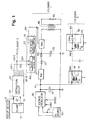
- pickup device 12 which can be connected to engine 10 by means of a conventional distributor, crank trigger or other source, and which can be triggered by the ignition “points" or by magnetic or optical means, produces a series of timing pulses 26 indicative of piston position.
- Separate sensor 13 provides signal 27 indicative of the position of the piston in cylinder 1. With these two signals, the precise location of any cylinder piston can be determined.
- Distribution circuit 20 receives the serial stream of timing pulses 26 and signal 27. Circuit 20 thereafter generates signals on parallel output lines 24-1 to 24-8 to control spark plug firing in the respective cylinders. In Fig. 1, distribution circuit 20 is shown having eight parallel output lines 24-1 to 24-8 for controlling plasma discharge in cylinders 1 to 8. Of course, the circuit is applicable to engines having any number of cylinders.
- Each one of output lines 24-1 to 24-8 is coupled to clock and timing circuit 22.
- each cylinder has its own clock and timing circuit 22.
- Timing circuit 22 for cylinder 1 receives its ON signal when it is required from output line 24-1
- timing circuit 22 for cylinder 2 receives its ON signal from output line 24-2 at the proper time, and so on.
- the OFF signal is the ON signal of a selected succeeding or other cylinder. For example, if it is desired to have a continuous ignition discharge for the entire power stroke of 180 crank angle degrees in an 8 cylinder engine, the OFF signal for cylinder 1 is the ON signal for cylinder 3, the OFF signal for cylinder 2 is the ON signal for cylinder 4, and so on.
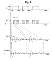
- Waveform A in Fig. 2 represents the ON/OFF period for the clock and timing circuit 22 of a typical cylinder operating in accordance with the present invention.
- clock 40 is coupled to flip-flop 41.
- circuit 22 produces pulses and platforms which control the ignition in the specified cylinder.
- pulse 70 and platform 72 of waveform B indicate voltages which appear on timing output line 44.
- Pulse 70 indicates the voltage at point 70 of Fig. 1 (at switch SW1 of cylinder 2), and typically lasts about 15 microseconds.
- Platform 72 indicates the voltage at point 72 of Fig. 1 (at switch SW2 of cylinder 2), and can last from 200 to 600 microseconds.
- timing circuit 22 receives an ON signal on line 24-1, the series of pulses 70 and platforms 72 shown in waveform B begin.
- Waveform C of Fig. 2 represents the voltage across the primary of ignition coil 46
- waveform D represents the current in the secondary winding of ignition coil 46. Note that current waveform D is 90 degrees out of phase from voltage waveform C.
- Platform 72 is periodically interrupted by pulses 70 to permit capacitor C2 to be recharged. Once an OFF signal is received, switch SW2 remains open until the next ON signal is received, thus allowing capacitor C2 to remain charged. After an ON signal is received, and until an OFF signal is received, clock and timing circuitry 22 will provide control signals which will allow capacitor C2 to discharge through the primary of ignition coil 46.
- Switch SW1 couples voltage V1 to inductor L1, which in turn is coupled to capacitor C2 and the input of second switch SW2 through diode 43.
- Voltage V1 is controlled by voltage regulator 60 connected to direct current voltage source 62, which preferably provides between 200 and 300 volts.
- direct current voltage sources are well known in the art, and may, for example, comprise an alternator with a rectifier).
- Inductor L1 and capacitor C2 are arranged so that when switch SW1 is closed, the voltage across capacitor C2 will rise to about twice voltage V1, typically between 400 and 600 volts.
- Voltage regulator 60 can adjust the voltage V1 based on any desired function or variable, including engine speed, load or fuel input.
- voltage regulator 60 can be controlled by a current or voltage proportional to speed as measured by engine rotation in revolutions per minute (RPM), or by a current or voltage proportional to fuel input as measured by throttle position or a signal to a fuel injector.
- RPM revolutions per minute
- each cylinder has its own switches SW1 and SW2, inductor L1, capacitor C2, ignition coil 46 and spark plug 50, as well as its own timing circuit 22.
- diode 43 may be interposed between inductor L1 and capacitor C2 to ensure that capacitor C2 will be charged to the maximum peak voltage.
- the spark plugs and ignition coil can be of the standard types readily available in the industry, or other types depending upon the particular application. In the alternative, more than one spark plug 50 may be connected to a single ignition coil, depending on the type of engine and particular desired operating characteristics.
- switches SW1 and SW2 can be silicon controlled rectifiers or MOSFET or bipolar transistors.
- switches depicted in more detail with respect to cylinder 2 of Fig. 1 one possible embodiment is shown where the switches comprise silicon controlled rectifiers (SCR) 81 and 82, and with diode 83 connected across SCR 82 to permit current to flow in both directions.
- controlling signals for SCRs 81 and 82 may be applied through one primary lead of a transformer, with the other primary lead of the transformer grounded.
- Capacitor C1 should have sufficient capacitance to assure that the voltage across it remains relatively constant regardless of the demands put on it by the engine during operation. In practice, a capacitor of approximately 470 microfarads has been found to be appropriate for this use, but generally it may be between about 200 and 2000 microfarads as determined by the requirements of the particular engine and application.
- Capacitor C2 is chosen such that its capacitance value and that of the net inductance of loaded ignition coil 46 allow the circuit to resonate at a frequency of about 2 to 15 kHz.
- a capacitance of approximately 1.5 microfarads has been found suitable for capacitor C2, although it may range from about 0.5 to 10 microfarads, with the optimum value for the capacitance of capacitor C2 depending on the particular requirements of the particular circuit and application.
- Waveforms C and D of Fig. 2 represent the voltage and current oscillations that occur when capacitor C2 is connected by switch SW2 to spark plug 50 through the primary winding of ignition coil 46.
- the waveforms are exponentially decreasing sinusoidal waves which repeat in a train of waveforms. There will be fewer members of this train of waveforms, that is, fewer capacitor discharges, as the time in each power stroke decreases. Indeed, at the highest engine speeds (above 5000 to 8000 RPM, depending on the particular engine application), there may be time for only a single discharge.
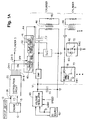
- FIG. 1A an embodiment of the present invention will now be described in which oscillatory discharge and recharge of capacitor C2 through the primary of ignition coil 46 is utilized to deliver discharge energy to spark plug 50 on a substantially continuous basis.
- Fig. 1A differs from the embodiment of Fig. 1 essentially in the following respects: the positions of capacitor C2 and switch SW2 have been exchanged (with switch SW2 also simplified in that the SCR may be controlled without a transformer); and inductor L1 and diode 43 have been eliminated. While the basic operation and timing of the embodiment of Fig. 1A is similar to the circuit of Fig. 1, additional benefits and advantages are achievable with the oscillatory discharge and recharge of capacitor C2 with the embodiment of Fig. 1A as discussed hereinafter.
- capacitor C2 discharges in an oscillatory manner through the primary of ignition coil 46.
- the frequency of the oscillatory discharge of C2 is principally determined by the capacitance of capacitor C2 and the reflected load presented by the primary of ignition coil 46.
- switch SW1 is closed and switch SW2 is opened.
- capacitor C2 recharges also in an oscillatory manner through the primary of ignition coil 46, again with the frequency of the oscillatory discharge principally determined by the capacitance of capacitor C2 and the reflected load presented by the primary of ignition coil 46.
- timing and control signals applied to switches SW1 and SW2 typically are adjusted from what is shown in Fig. 2 so that, in preferred embodiments, the discharge and recharges durations are approximately the same, although the precise timing relationships for optimum operation may vary depending upon the particular application.
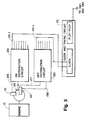
- pickup device 112 generates a continuous series of timing pulses along line 126, which, along with cylinder 1 identifying pulse 127 generated by conventional pickup or other identifying element 115, are the inputs to ON signal distribution circuit 120, which, in turn, generates a series of individual ON pulses 124 that are sent to the ignition circuits of individual cylinders in the proper predetermined sequence.
- second pickup device 114 which typically is of the same type as pickup device 112, is physically positioned some desired number of crank angle degrees (preferably from 15 to 330 degrees depending on the engine) behind first pickup device 112.
- Pickup device 114 generates a second series of OFF timing pulses 136, which pulses occur the selected number of crank angle degrees after the corresponding ON timing pulses 126.
- the cylinder ignition and switching electronics for the embodiment of Fig. 3 may be similar to those of the embodiments of Figs. 1 or 1A.
- the continuous series of OFF timing pulses 136, along with cylinder 1 identifying pulse 127, are the inputs to OFF pulse distribution circuit 130.
- This circuit similar to ON distribution circuit 120, generates a series of OFF pulses 134 that are distributed to the corresponding cylinder ignition circuits turned on by ON pulses 124.
- ON pulse 124-1 For example, if continuous ignition discharge is initiated in cylinder 1 by ON pulse 124-1, it can be turned OFF by cylinder 1 OFF pulse 134-1.
- the timing system illustrated in Fig. 3 allows the ignition discharge interval to be selected to have any desired duration in crank angle degrees.
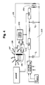
- FIG. 4 an embodiment of the present invention is illustrated that uses conventional distributor 218 to generate the timing pulses for timing circuit 222, which is similar to timing circuits 22 described with reference to Fig. 1.
- distributor 218 has either mechanical "points” or magnetic or optical ON and OFF sensors 212 and 214 that generate ON and OFF timing pulses that control single timing circuit 222, which controls single ignition energy generating circuit 223.
- Circuit 223 is similar to the ignition circuits described in the embodiment shown in Fig. 1. However, with the embodiment of Fig. 4, only one ignition circuit is needed, rather than an ignition circuit per cylinder as with the embodiment of Fig. 1.
- the output from single ignition coil 250 is distributed to the appropriate cylinder at the proper time by the rotor and distributor cap of distributor 218.
- Rotor "blade" 216 is broadened sufficiently to distribute the ignition energy over a wide angle to the individual spark plugs by stator electrodes 217.
- ignition energy may be provided in each cylinder over, for example, about 45 to 70 crankshaft angle degrees.
- This embodiment has been demonstrated on a dynamometer to produce 40 more horsepower, a 12% increase, while consuming 8% less fuel than a conventional high energy ignition system previously used on the same engine.
- an ignition system in accordance with the present invention Under conditions of exhaust gas recirculation ("EGR") of up to 20%, an ignition system in accordance with the present invention had essentially constant output and fuel consumption over the ignition timing range of 40 to 100° before top dead center. Under the same EGR conditions, the conventional spark ignition system could operate only in a narrow range of a few degrees in ignition timing to which the engine had to be precisely tuned to achieve maximum efficiency. Adoption of the ignition system according to the present invention should make it possible to substantially eliminate both timing controls and the need for high-test or high octane gasoline in engines.
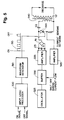
- Fig. 5 An alternative embodiment of the electronic ignition system is illustrated in Fig. 5.
- ON and OFF signals generated by any of the embodiments described above, are amplified and sharpened in input logic processor 300, which turns on waveform generator 310 to produce waveform 315.
- Waveform 315 is applied to the gate of SCR 320, which acts as a switch to discharge capacitor C2.
- Capacitor C2 is charged to a high DC voltage by the rectified output of oscillator 325, buffer 330, and amplifier 335, which are normally on.
- SCR 320 conducts, a voltage is sensed due to the current that flows in the circuit comprising SCR 320, capacitor C2, and the primary of ignition coil 340. This voltage is amplified by amplifier 345 and acts to turn off buffer 330.
- SCR 320 When the voltage in waveform 315 is LOW, SCR 320 does not conduct and oscillator 325, buffer 330, and amplifier 335 again function at full power to recharge capacitor C2 so that it can be discharged again when the gate of SCR 320 is turned on by the succeeding HIGH voltage platform of waveform 315.
- Oscillator 325 runs continuously at a frequency between 18 and 100 kilohertz, and in preferred embodiments is about 90 kilohertz.
- the embodiment illustrated in Fig. 5 has the advantage of instant cut off and instant restart of chain comprising oscillator 325, buffer 330, amplifier 335, resulting in a fast recharge of capacitor C2. Because oscillator 325 runs continuously, there is no delay in start up, as there is when using self-excited inverters that are common in previous capacitive discharge ignition systems. Another advantage of this embodiment is that the turn-off and turn-on is accomplished at low power levels in the buffer stage, allowing all controls to be at low power using TTL and CMOS logic elements.
- Waveforms C and D of Fig. 2 are exponentially decaying sinusoids. There are no pulses or sparks.
- the secondary circuit current waveform D compared to the primary circuit voltage waveform C shows the essentially identical form of both applied voltage and "spark"-plug current.
- the continuous current waveform demonstrates that the discharge has generated a long lasting plasma that is ideal for stabilizing combustion and achieving optimum combustion.
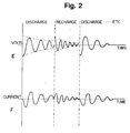
- Waveforms that may be generated by this preferred embodiment of the present invention will now be discussed in greater detail with reference to waveforms E and F of Fig. 2.
- Waveform E of Fig. 2 expands waveforms C and D of Fig. 2 and illustrate that, in the time interval between the oscillatory discharges of capacitor C2 in Fig. 5, produced by platforms 315, the current that recharges capacitor C2 also passes through the primary of ignition coil 340.
- This rectified but unfiltered DC current due to high frequency AC components generated by amplifier 335 of Fig. 5, also has an oscillatory component that can be made to produce an additional spark plug discharge during oscillatory recharge of capacitor C2.
- the frequency components of the oscillator recharge depend primarily from the output of amplifier 335, and thus, in general, are of a frequency unrelated to and different from the resonance frequency during discharge.
- the waveforms of Fig. 2 are generalizations of the more complex waveforms actually produced, which may include, for example, other frequency components and/or harmonics, particularly with embodiments such as discussed above with respect to Fig. 5. In any event, as with the embodiment discussed with reference to Fig. 1A, and as illustrated by waveforms E and F of Fig.
- oscillatory discharges and recharges of capacitor C2 induce oscillatory voltages across the primary of ignition coil 340 (such as shown in waveform E), and correspondingly induce oscillatory current in the secondary of ignition coil 340 (such as shown in waveform F).
- the high frequency components from amplifier 335 may be desirably generated, for example, by filtering the output of amplifier 335 with suitable capacitor C3 connected as shown in Fig. 5.
- capacitor C3 With a nearly ideal square wave output from amplifier 335, bridge rectifier R1 produces a DC signal with little AC components. With capacitor C3, however, higher harmonics are removed from the square wave output of amplifier 335, thereby resulting in a significant AC signal component being produced on the output of rectifier R1.
- the duty cycle of the signal output from amplifier may be controlled to be other than the 50% duty cycle for the ideal square wave, which also will result in a significant AC signal components being produced on the output of rectifier R1.
- Other methods for generating suitable AC components will be apparent to those skilled in the art.
- the embodiment of the present invention illustrated in Fig. 5 also can be made to produce spark plug discharges as illustrated by waveforms E and F of Fig. 2 both during discharging as well as recharging of capacitor C2.
- the use of the discharging as well as the recharging current significantly extends and lengthens the duration of the spark plug discharge, increases the ignition capability of the present invention, and increases its energy efficiency.
Landscapes
- Engineering & Computer Science (AREA)
- Chemical & Material Sciences (AREA)
- Combustion & Propulsion (AREA)
- Mechanical Engineering (AREA)
- General Engineering & Computer Science (AREA)
- Ignition Installations For Internal Combustion Engines (AREA)
Claims (15)
- Procédé pour enflammer du carburant par l'usage d'un allumeur de carburant (50) couplé à l'enroulement secondaire d'une bobine d'allumage (46) pourvue également d'un enroulement primaire, consistant à décharger et à recharger un condensateur (C2) à travers l'enroulement primaire de la bobine d'allumage, caractérisé en ce que le condensateur (C2) est déchargé selon un processus oscillatoire résonnant et rechargé selon un processus oscillatoire résonnant à travers l'enroulement primaire de la bobine d'allumage (46) pour fournir, d'une façon sensiblement continue, de l'énergie à l'allumeur de carburant (50) à la fois pendant les cycles de décharge et de recharge.
- Procédé selon la revendication 1, caractérisé en ce que la décharge du condensateur (C2) produit un signal de tension sinusoïdal amorti d'une première fréquence caractéristique à travers le primaire de la bobine d'allumage (46).
- Procédé selon la revendication 1 ou 2, caractérisé en ce que la recharge du condensateur (C2) produit un signal de tension sinusoïdal amorti d'une seconde fréquence caractéristique à travers le primaire de la bobine d'allumage (46).
- Procédé selon l'une quelconque des revendications précédentes, caractérisé en ce qu'à la fois la décharge et la recharge du condensateur (C2) produisent des signaux de tension sinusoïdaux amortis, respectivement de première et de seconde fréquences caractéristiques.
- Procédé selon la revendication 4, caractérisé en ce que la première fréquence caractéristique est sensiblement la même que la seconde fréquence caractéristique.
- Procédé selon l'une quelconque des revendications précédentes, caractérisé en ce que la recharge du condensateur (C2) est effectuée en appliquant au condensateur (C2) un signal ayant une composante oscillatoire.
- Appareil pour enflammer du carburant comprenant :une bobine d'allumage (46) pourvue d'enroulements primaire et secondaire;un allumeur de carburant (50) couplé à l'enroulement secondaire de la bobine d'allumage (46) pour enflammer le carburant;un condensateur (C2) couplé à l'enroulement primaire de la bobine d'allumage (46); etdes moyens de synchronisation et de commutation (12, 13, 20, 22, SW1, SW2) pour décharger et recharger le condensateur (C2) de façon contrôlée à travers l'enroulement primaire de la bobine d'allumage (46), caractérisé en ce que la décharge, aussi bien que la recharge du condensateur (C2) s'effectuent suivant un processus oscillatoire résonnant.
- Appareil selon la revendication 7, caractérisé en ce que la décharge du condensateur (C2) produit un signal de tension sinusoïdal amorti d'une première fréquence caractéristique à travers le primaire de la bobine d'allumage (46).
- Appareil selon la revendication 7 ou 8, caractérisé en ce que la recharge du condensateur (C2) produit un signal de tension sinusoïdal amorti d'une seconde fréquence caractéristique à travers le primaire de la bobine d'allumage (46).
- Appareil selon l'une quelconque des revendications 7 à 8, caractérisé en ce qu'aussi bien la décharge que la recharge du condensateur (C2) produisent des signaux de tension sinusoïdaux amortis, respectivement d'une première et d'une seconde fréquence caractéristique à travers le primaire de la bobine d'allumage (46).
- Appareil selon la revendication 10, caractérisé en ce que la première fréquence caractéristique est sensiblement la même que la seconde fréquence caractéristique.
- Appareil selon l'une quelconque des revendications 7 à 11, caractérisé en ce que la source de tension de charge comprend :une source d'alimentation en courant continu (62) ayant une sortie de tension ; etun condensateur (C1) connecté entre la sortie de tension de la source d'alimentation en courant continu et un potentiel de référence ;un régulateur de tension (60) ayant une entrée et une sortie de tension régulée, l'entrée du régulateur de tension (60) étant connectée à la sortie de tension de la source d'alimentation en courant continu (62) et la sortie du régulateur de tension (60) étant connectée au condensateur (C2).
- Appareil selon l'une quelconque des revendications 7 à 12, caractérisé en ce que les moyens de synchronisation et de commutation (12, 13, 20, 22, SW1, SW2) comprennent :des moyens de commande de circuit (22) pour générer des signaux de synchronisation comprenant des premier et second signaux de synchronisation ;un premier moyens de commutation (22) pour coupler le condensateur (C2) à l'enroulement primaire de la bobine d'allumage (46), le premier moyens de commutation (SW2) étant également couplé aux moyens de commande de circuit (22) et réagissant au premier signal de synchronisation, dans lequel la décharge du condensateur (C2) à travers l'enroulement primaire de la bobine d'allumage (46) est déclenchée en réponse au premier signal de synchronisation; etun deuxième moyens de commutation (SW1) pour coupler le condensateur (C2) à la source de tension de charge (62), le deuxième moyens de commutation (SW1) étant également couplé aux moyens de commande de circuit (22) et réagissant au second signal de synchronisation, dans lequel la recharge du condensateur (C2) à travers l'enroulement primaire de la bobine d'allumage (46) est déclenchée par le second signal de synchronisation .
- Appareil selon l'une quelconque des revendications 7 à 13, caractérisé en ce que la source de tension de charge comprend :une source de tension générant une tension de sortie ayant une composante continue et une composante alternative de haute fréquence, etun redresseur (R1) connecté à la source de tension et au condensateur (C2), et aux moyens de synchronisation et de commutation (12, 13, 20, 22, SW1, SW2.)
- Appareil selon la revendication 14, caractérisé en ce que la source de tension comprend :un oscillateur (325),un amplificateur tampon (330) couplé à l'oscillateur (325),un amplificateur de sortie (335) couplé à l'amplificateur tampon (330),l'amplificateur de sortie (335) ayant une sortie sur laquelle est générée une tension de sortie ayant une composante continue et une composante alternative de haute fréquence ; etun condensateur (C2) connecté à la sortie de l'amplificateur de sortie.
Applications Claiming Priority (3)
| Application Number | Priority Date | Filing Date | Title |
|---|---|---|---|
| US07/761,682 US5429103A (en) | 1991-09-18 | 1991-09-18 | High performance ignition system |
| US761682 | 1991-09-18 | ||
| PCT/US1992/007885 WO1993006364A1 (fr) | 1991-09-18 | 1992-09-17 | Procede et appareil d'allumage performant |
Publications (3)
| Publication Number | Publication Date |
|---|---|
| EP0640180A4 EP0640180A4 (fr) | 1994-10-25 |
| EP0640180A1 EP0640180A1 (fr) | 1995-03-01 |
| EP0640180B1 true EP0640180B1 (fr) | 1999-06-09 |
Family
ID=25062958
Family Applications (1)
| Application Number | Title | Priority Date | Filing Date |
|---|---|---|---|
| EP92920570A Expired - Lifetime EP0640180B1 (fr) | 1991-09-18 | 1992-09-17 | Procede et appareil d'allumage performant |
Country Status (5)
| Country | Link |
|---|---|
| US (1) | US5429103A (fr) |
| EP (1) | EP0640180B1 (fr) |
| JP (1) | JPH07501866A (fr) |
| DE (1) | DE69229405T2 (fr) |
| WO (1) | WO1993006364A1 (fr) |
Families Citing this family (13)
| Publication number | Priority date | Publication date | Assignee | Title |
|---|---|---|---|---|
| JP3102993B2 (ja) * | 1994-07-19 | 2000-10-23 | 三菱電機株式会社 | 内燃機関用点火コイル |
| AU3485397A (en) * | 1996-06-21 | 1998-01-07 | Outboard Marine Corporation | Multiple spark capacitive discharge ignition system for an internal combustion engine |
| US5852999A (en) * | 1997-02-13 | 1998-12-29 | Caterpillar Inc. | Method and means for generating and maintaining spark in a varying pressure environment |
| US6289868B1 (en) | 2000-02-11 | 2001-09-18 | Michael E. Jayne | Plasma ignition for direct injected internal combustion engines |
| CN101218722B (zh) * | 2005-04-19 | 2011-11-30 | 奈特公司 | 用于在高压力下操作移动式火花点火器的方法和装置 |
| DE102006005792B4 (de) * | 2006-02-07 | 2018-04-26 | Fachhochschule Aachen | Hochfrequenzzündanlage für Kraftfahrzeuge |
| US7401603B1 (en) | 2007-02-02 | 2008-07-22 | Altronic, Inc. | High tension capacitive discharge ignition with reinforcing triggering pulses |
| US8289117B2 (en) | 2010-06-15 | 2012-10-16 | Federal-Mogul Corporation | Ignition coil with energy storage and transformation |
| US20140232256A1 (en) | 2011-07-26 | 2014-08-21 | Knite, Inc. | Traveling spark igniter |
| JP5255682B2 (ja) * | 2011-10-17 | 2013-08-07 | 三菱電機株式会社 | 点火装置 |
| JP5496297B2 (ja) * | 2012-10-02 | 2014-05-21 | 三菱電機株式会社 | 内燃機関の点火装置 |
| US9856800B2 (en) | 2013-11-22 | 2018-01-02 | Nxp Usa, Inc. | Ignition control device having an electronic fuel injection (EFI) mode and a capacitive discharge ignition (CDI) mode |
| CN114909674B (zh) * | 2022-05-25 | 2024-02-06 | 西安热工研究院有限公司 | 基于燃煤机组的自启动等离子点火控制系统 |
Citations (1)
| Publication number | Priority date | Publication date | Assignee | Title |
|---|---|---|---|---|
| US3302629A (en) * | 1964-09-21 | 1967-02-07 | Motorola Inc | Capacitor discharge ignition system with blocking oscillator charging circuit |
Family Cites Families (64)
| Publication number | Priority date | Publication date | Assignee | Title |
|---|---|---|---|---|
| US3081360A (en) * | 1959-11-12 | 1963-03-12 | Economy Engine Co | Ignition systems for internal combustion engines |
| AT279272B (de) * | 1967-03-23 | 1970-02-25 | Bosch Gmbh Robert | Zündeinrichtung für Brennkraftmaschinen |
| NL6705849A (fr) * | 1967-04-26 | 1967-07-25 | ||
| US3545419A (en) * | 1968-09-30 | 1970-12-08 | Texaco Inc | High frequency spark discharge system |
| DE2048960A1 (de) * | 1970-10-06 | 1972-04-13 | Bosch Gmbh Robert | Kondensatorzündanlage für Brennkraftmaschinen |
| US3718125A (en) * | 1971-04-05 | 1973-02-27 | T Posey | Capacitor discharge ignition system |
| IT967430B (it) * | 1971-09-14 | 1974-02-28 | Licentia Gmbh | Impianto di accensione con con densatori per alta tensione in particolare per motori a ciclo di otto e wankel |
| GB1410471A (en) * | 1971-11-16 | 1975-10-15 | Ass Eng Ltd | Ignition devices |
| US3897767A (en) * | 1972-11-13 | 1975-08-05 | Edwards Edwin Melville | Internal combustion engine ignition |
| US3818885A (en) * | 1973-02-20 | 1974-06-25 | Texaco Inc | High-frequency continuous-wave ignition system |
| US3838328A (en) * | 1973-03-19 | 1974-09-24 | W Lundy | Capacitive discharge ignition system |
| US3945362A (en) * | 1973-09-17 | 1976-03-23 | General Motors Corporation | Internal combustion engine ignition system |
| US4161936A (en) * | 1974-01-24 | 1979-07-24 | Volsky Bill V | Audio frequency ionization ignition system |
| US4061113A (en) * | 1974-01-29 | 1977-12-06 | Roland Beyler | Process for reducing the pollution due to an internal combustion engine, and an engine including the application of said process |
| US3926165A (en) * | 1974-02-11 | 1975-12-16 | Autotronic Controls Corp | Multiple spark discharge system |
| US3906919A (en) * | 1974-04-24 | 1975-09-23 | Ford Motor Co | Capacitor discharge ignition system with controlled spark duration |
| US3934570A (en) * | 1974-04-24 | 1976-01-27 | Ford Motor Company | Ferroresonant capacitor discharge ignition system |
| DE2529724C3 (de) * | 1975-07-03 | 1982-02-25 | Kyberna Gmbh, 6140 Bensheim | Zündvorrichtung für eine Brennkraftmaschine |
| US4051828A (en) * | 1975-12-29 | 1977-10-04 | Eugene Frank Topic | Ignition system for use with internal combustion engines |
| DE2616693C3 (de) * | 1976-04-15 | 1980-09-18 | Robert Bosch Gmbh, 7000 Stuttgart | Zündanlage für Brennkraftmaschinen |
| DE2619556A1 (de) * | 1976-05-04 | 1977-11-24 | Bosch Gmbh Robert | Zuendanlage, insbesondere fuer brennkraftmaschinen |
| DE2623865A1 (de) * | 1976-05-28 | 1977-12-08 | Bosch Gmbh Robert | Zuendanlage, insbesondere fuer brennkraftmaschinen |
| DE2623864A1 (de) * | 1976-05-28 | 1977-12-08 | Bosch Gmbh Robert | Zuendanlage, insbesondere fuer brennkraftmaschinen |
| US4068643A (en) * | 1976-05-28 | 1978-01-17 | Mckechnie Ian C | Multiple spark ignition system |
| US4192275A (en) * | 1976-11-03 | 1980-03-11 | Weydemuller Donald C | Electronic ignition system |
| FR2376305A2 (fr) * | 1976-12-29 | 1978-07-28 | Snecma | Procede de reduction de la pollution due aux moteurs a combustion interne et moteur en comportant application |
| JPS53123731A (en) * | 1977-04-06 | 1978-10-28 | Ngk Spark Plug Co Ltd | Ignition system |
| US4131100A (en) * | 1977-04-26 | 1978-12-26 | Autotronic Controls, Corp. | Multiple spark discharge circuitry |
| US4149508A (en) * | 1977-07-27 | 1979-04-17 | Kirk Jr Donald | Electronic ignition system exhibiting efficient energy usage |
| US4301782A (en) * | 1977-09-21 | 1981-11-24 | Wainwright Basil E | Ignition system |
| US4174695A (en) * | 1977-10-25 | 1979-11-20 | Texaco Inc. | AC type ignition system with two time delay circuits |
| US4208992A (en) * | 1978-03-20 | 1980-06-24 | Benito Polo | Electronic ignition system |
| JPS5519938A (en) * | 1978-07-27 | 1980-02-13 | Nippon Soken Inc | Ignition system in engine |
| JPS5560665A (en) * | 1978-10-31 | 1980-05-07 | Nippon Soken Inc | Auxiliary device for starting of diesel engine |
| US4288723A (en) * | 1979-05-01 | 1981-09-08 | Gerry Martin E | Inductive-capacitive cyclic charge-discharge ignition system |
| US4428349A (en) * | 1979-05-17 | 1984-01-31 | Snow Thomas K | Ignition and fuel control system for internal combustion engines |
| US4326493A (en) * | 1979-07-26 | 1982-04-27 | Autotronic Controls, Corp. | Multiple spark discharge ignition system |
| JPS5620769A (en) * | 1979-07-30 | 1981-02-26 | Nippon Soken Inc | Igniter |
| JPS5634964A (en) * | 1979-08-31 | 1981-04-07 | Nippon Soken Inc | Ignition device |
| US4345576A (en) * | 1979-09-24 | 1982-08-24 | Super Shops, Inc. | Multi-spark CD ignition |
| US4359998A (en) * | 1979-11-28 | 1982-11-23 | Topic Eugene F | Ignition system for internal combustion engines |
| US4407255A (en) * | 1980-07-14 | 1983-10-04 | Butler James G | Apparatus for supplying high voltage pulses |
| JPS5732069A (en) * | 1980-07-31 | 1982-02-20 | Nissan Motor Co Ltd | Igniter for internal combustion engine |
| US4414954A (en) * | 1982-05-27 | 1983-11-15 | Texaco Inc. | Internal combustion engine ignition system with improvement |
| US4438751A (en) * | 1982-06-01 | 1984-03-27 | Aisin Seiki Kabushiki Kaisha | High voltage generating circuit for an automotive ignition system |
| US4476844A (en) * | 1982-09-17 | 1984-10-16 | Yukio Kajino | Method of and apparatus for igniting internal combustion engine |
| US4608958A (en) * | 1982-09-22 | 1986-09-02 | Nippon Soken, Inc. | Load reactance element driving device |
| US4479467A (en) * | 1982-12-20 | 1984-10-30 | Outboard Marine Corporation | Multiple spark CD ignition system |
| US4562823A (en) * | 1983-07-15 | 1986-01-07 | Nippon Soken, Inc. | Ignition device for internal combustion engine |
| US4522185A (en) * | 1983-11-14 | 1985-06-11 | Nguyen Minh Tri | Switching electronic ignition |
| US4653459A (en) * | 1984-08-23 | 1987-03-31 | Robert Bosch Gmbh | Method and apparatus for igniting a combustible mixture, especially gasoline-air in the combustion chamber of an internal combustion engine |
| US4688538A (en) * | 1984-12-31 | 1987-08-25 | Combustion Electromagnetics, Inc. | Rapid pulsed multiple pulse ignition and high efficiency power inverter with controlled output characteristics |
| EP0228840B1 (fr) * | 1986-01-07 | 1991-07-17 | LUCAS INDUSTRIES public limited company | Circuit générateur d'impulsion pour système d'allumage |
| US4710681A (en) * | 1986-02-18 | 1987-12-01 | Aleksandar Zivkovich | Process for burning a carbonaceous fuel using a high-energy alternating current wave |
| US4820957A (en) * | 1986-02-18 | 1989-04-11 | Aleksandar Zivkovich | Process for burning a carbonaceous fuel using a high energy alternating current wave |
| US4686954A (en) * | 1986-04-11 | 1987-08-18 | Stanley L. Dembecki | High performance digital ignition system for internal combustion engines |
| US4784105A (en) * | 1986-04-11 | 1988-11-15 | Brown Craig R | High performance digital ignition system for internal combustion engines |
| IT1204274B (it) * | 1986-04-24 | 1989-03-01 | Claudio Filippone | Dispositivo di accensione a controllo elettronico di plasma,per motori a combustione interna |
| US4733646A (en) * | 1986-04-30 | 1988-03-29 | Aisin Seiki Kabushiki Kaisha | Automotive ignition systems |
| EP0274513A4 (fr) * | 1986-07-15 | 1989-02-22 | Comb Electromagnetics Inc | Pompe a courant de convertisseur cc-cc. |
| JPH01116281A (ja) * | 1987-10-29 | 1989-05-09 | Aisin Seiki Co Ltd | 点火装置 |
| US4839772A (en) * | 1988-03-21 | 1989-06-13 | Bang H. Mo | Capacitive discharge electronic ignition system for automobiles |
| IT1223928B (it) * | 1988-11-22 | 1990-09-29 | Marelli Autronica | Sistema di accensione per un motore a combustione interna |
| DE69031878T2 (de) * | 1989-03-14 | 1998-05-28 | Denso Corp | Zündvorrichtung mit mehrfacher Funkenzündung |
-
1991
- 1991-09-18 US US07/761,682 patent/US5429103A/en not_active Expired - Fee Related
-
1992
- 1992-09-17 JP JP5506232A patent/JPH07501866A/ja active Pending
- 1992-09-17 WO PCT/US1992/007885 patent/WO1993006364A1/fr not_active Ceased
- 1992-09-17 DE DE69229405T patent/DE69229405T2/de not_active Expired - Fee Related
- 1992-09-17 EP EP92920570A patent/EP0640180B1/fr not_active Expired - Lifetime
Patent Citations (1)
| Publication number | Priority date | Publication date | Assignee | Title |
|---|---|---|---|---|
| US3302629A (en) * | 1964-09-21 | 1967-02-07 | Motorola Inc | Capacitor discharge ignition system with blocking oscillator charging circuit |
Also Published As
| Publication number | Publication date |
|---|---|
| DE69229405D1 (de) | 1999-07-15 |
| DE69229405T2 (de) | 2000-02-17 |
| EP0640180A4 (fr) | 1994-10-25 |
| EP0640180A1 (fr) | 1995-03-01 |
| US5429103A (en) | 1995-07-04 |
| JPH07501866A (ja) | 1995-02-23 |
| WO1993006364A1 (fr) | 1993-04-01 |
Similar Documents
| Publication | Publication Date | Title |
|---|---|---|
| US5513618A (en) | High performance ignition apparatus and method | |
| US4398526A (en) | Plasma ignition system for internal combustion engine | |
| US4149508A (en) | Electronic ignition system exhibiting efficient energy usage | |
| US5429103A (en) | High performance ignition system | |
| US4441479A (en) | Ignition system for a multi-cylinder internal combustion engine of a vehicle | |
| US5178120A (en) | Direct current ignition system | |
| WO1988001690A1 (fr) | Procede et dispositif servant a produire des etincelles d'allumage dans un moteur a combustion interne | |
| US6662792B2 (en) | Capacitor discharge ignition (CDI) system | |
| US4820957A (en) | Process for burning a carbonaceous fuel using a high energy alternating current wave | |
| Johnston et al. | Programmable energy ignition system for engine optimization | |
| JP2822736B2 (ja) | 内燃機関用点火装置 | |
| JPS59705B2 (ja) | 内燃機関点火装置 | |
| US5109827A (en) | Ignition apparatus for an internal combustion engine | |
| US6799557B2 (en) | Processor controlled discharge ignition with fixed firing angle at startup | |
| WO1994015094A1 (fr) | Systeme d'allumage capacitif pour moteurs a explosion | |
| US7066161B2 (en) | Capacitive discharge ignition system | |
| JPS6127589B2 (fr) | ||
| JP2525979B2 (ja) | ガソリン機関の燃焼状態検出装置 | |
| JPS5859370A (ja) | 内燃機関の点火装置 | |
| JPS61241466A (ja) | 内燃機関の点火装置 | |
| JPH0578672B2 (fr) | ||
| JPH078844Y2 (ja) | 内燃機関用点火装置 | |
| JPS62103466A (ja) | 内燃機関用点火時期制御装置 | |
| AU681368C (en) | Capacitive ignition system for internal combustion engines | |
| AU681368B2 (en) | Capacitive ignition system for internal combustion engines |
Legal Events
| Date | Code | Title | Description |
|---|---|---|---|
| A4 | Supplementary search report drawn up and despatched | ||
| AK | Designated contracting states |
Kind code of ref document: A4 Designated state(s): DE FR GB IT SE |
|
| PUAI | Public reference made under article 153(3) epc to a published international application that has entered the european phase |
Free format text: ORIGINAL CODE: 0009012 |
|
| 17P | Request for examination filed |
Effective date: 19940415 |
|
| AK | Designated contracting states |
Kind code of ref document: A1 Designated state(s): DE FR GB IT SE |
|
| 17Q | First examination report despatched |
Effective date: 19960701 |
|
| RAP1 | Party data changed (applicant data changed or rights of an application transferred) |
Owner name: ENOX TECHNOLOGIES, INC. |
|
| RAP1 | Party data changed (applicant data changed or rights of an application transferred) |
Owner name: COOPER CAMERON CORPORATION |
|
| GRAG | Despatch of communication of intention to grant |
Free format text: ORIGINAL CODE: EPIDOS AGRA |
|
| GRAG | Despatch of communication of intention to grant |
Free format text: ORIGINAL CODE: EPIDOS AGRA |
|
| GRAH | Despatch of communication of intention to grant a patent |
Free format text: ORIGINAL CODE: EPIDOS IGRA |
|
| GRAH | Despatch of communication of intention to grant a patent |
Free format text: ORIGINAL CODE: EPIDOS IGRA |
|
| GRAA | (expected) grant |
Free format text: ORIGINAL CODE: 0009210 |
|
| AK | Designated contracting states |
Kind code of ref document: B1 Designated state(s): DE FR GB IT SE |
|
| PG25 | Lapsed in a contracting state [announced via postgrant information from national office to epo] |
Ref country code: SE Free format text: THE PATENT HAS BEEN ANNULLED BY A DECISION OF A NATIONAL AUTHORITY Effective date: 19990609 Ref country code: IT Free format text: LAPSE BECAUSE OF FAILURE TO SUBMIT A TRANSLATION OF THE DESCRIPTION OR TO PAY THE FEE WITHIN THE PRESCRIBED TIME-LIMIT;WARNING: LAPSES OF ITALIAN PATENTS WITH EFFECTIVE DATE BEFORE 2007 MAY HAVE OCCURRED AT ANY TIME BEFORE 2007. THE CORRECT EFFECTIVE DATE MAY BE DIFFERENT FROM THE ONE RECORDED. Effective date: 19990609 Ref country code: FR Free format text: LAPSE BECAUSE OF FAILURE TO SUBMIT A TRANSLATION OF THE DESCRIPTION OR TO PAY THE FEE WITHIN THE PRESCRIBED TIME-LIMIT Effective date: 19990609 |
|
| REF | Corresponds to: |
Ref document number: 69229405 Country of ref document: DE Date of ref document: 19990715 |
|
| K2C1 | Correction of patent specification (title page) published |
Effective date: 19990609 |
|
| EN | Fr: translation not filed | ||
| PLBE | No opposition filed within time limit |
Free format text: ORIGINAL CODE: 0009261 |
|
| STAA | Information on the status of an ep patent application or granted ep patent |
Free format text: STATUS: NO OPPOSITION FILED WITHIN TIME LIMIT |
|
| 26N | No opposition filed | ||
| REG | Reference to a national code |
Ref country code: GB Ref legal event code: IF02 |
|
| PGFP | Annual fee paid to national office [announced via postgrant information from national office to epo] |
Ref country code: GB Payment date: 20060804 Year of fee payment: 15 |
|
| PGFP | Annual fee paid to national office [announced via postgrant information from national office to epo] |
Ref country code: DE Payment date: 20060929 Year of fee payment: 15 |
|
| GBPC | Gb: european patent ceased through non-payment of renewal fee |
Effective date: 20070917 |
|
| PG25 | Lapsed in a contracting state [announced via postgrant information from national office to epo] |
Ref country code: DE Free format text: LAPSE BECAUSE OF NON-PAYMENT OF DUE FEES Effective date: 20080401 |
|
| PG25 | Lapsed in a contracting state [announced via postgrant information from national office to epo] |
Ref country code: GB Free format text: LAPSE BECAUSE OF NON-PAYMENT OF DUE FEES Effective date: 20070917 |