EP0640197B1 - Rohrförmiges rahmensystem - Google Patents
Rohrförmiges rahmensystem Download PDFInfo
- Publication number
- EP0640197B1 EP0640197B1 EP93903601A EP93903601A EP0640197B1 EP 0640197 B1 EP0640197 B1 EP 0640197B1 EP 93903601 A EP93903601 A EP 93903601A EP 93903601 A EP93903601 A EP 93903601A EP 0640197 B1 EP0640197 B1 EP 0640197B1
- Authority
- EP
- European Patent Office
- Prior art keywords
- closed tubular
- tubular member
- open channel
- closed
- additional
- Prior art date
- Legal status (The legal status is an assumption and is not a legal conclusion. Google has not performed a legal analysis and makes no representation as to the accuracy of the status listed.)
- Expired - Lifetime
Links
- 238000009432 framing Methods 0.000 title claims abstract description 20
- 210000005069 ears Anatomy 0.000 claims description 6
- 230000008878 coupling Effects 0.000 description 2
- 238000010168 coupling process Methods 0.000 description 2
- 238000005859 coupling reaction Methods 0.000 description 2
- 230000013011 mating Effects 0.000 description 2
- 230000002093 peripheral effect Effects 0.000 description 2
- OKTJSMMVPCPJKN-UHFFFAOYSA-N Carbon Chemical compound [C] OKTJSMMVPCPJKN-UHFFFAOYSA-N 0.000 description 1
- 229910000831 Steel Inorganic materials 0.000 description 1
- 229910052799 carbon Inorganic materials 0.000 description 1
- 230000004048 modification Effects 0.000 description 1
- 238000012986 modification Methods 0.000 description 1
- 239000010959 steel Substances 0.000 description 1
Images

Classifications
-
- F—MECHANICAL ENGINEERING; LIGHTING; HEATING; WEAPONS; BLASTING
- F16—ENGINEERING ELEMENTS AND UNITS; GENERAL MEASURES FOR PRODUCING AND MAINTAINING EFFECTIVE FUNCTIONING OF MACHINES OR INSTALLATIONS; THERMAL INSULATION IN GENERAL
- F16B—DEVICES FOR FASTENING OR SECURING CONSTRUCTIONAL ELEMENTS OR MACHINE PARTS TOGETHER, e.g. NAILS, BOLTS, CIRCLIPS, CLAMPS, CLIPS OR WEDGES; JOINTS OR JOINTING
- F16B19/00—Bolts without screw-thread; Pins, including deformable elements; Rivets
- F16B19/04—Rivets; Spigots or the like fastened by riveting
- F16B19/08—Hollow rivets; Multi-part rivets
- F16B19/10—Hollow rivets; Multi-part rivets fastened by expanding mechanically
- F16B19/1027—Multi-part rivets
- F16B19/1036—Blind rivets
- F16B19/1081—Blind rivets fastened by a drive-pin
-
- E—FIXED CONSTRUCTIONS
- E04—BUILDING
- E04B—GENERAL BUILDING CONSTRUCTIONS; WALLS, e.g. PARTITIONS; ROOFS; FLOORS; CEILINGS; INSULATION OR OTHER PROTECTION OF BUILDINGS
- E04B1/00—Constructions in general; Structures which are not restricted either to walls, e.g. partitions, or floors or ceilings or roofs
- E04B1/18—Structures comprising elongated load-supporting parts, e.g. columns, girders, skeletons
- E04B1/24—Structures comprising elongated load-supporting parts, e.g. columns, girders, skeletons the supporting parts consisting of metal
- E04B1/2403—Connection details of the elongated load-supporting parts
-
- E—FIXED CONSTRUCTIONS
- E04—BUILDING
- E04B—GENERAL BUILDING CONSTRUCTIONS; WALLS, e.g. PARTITIONS; ROOFS; FLOORS; CEILINGS; INSULATION OR OTHER PROTECTION OF BUILDINGS
- E04B1/00—Constructions in general; Structures which are not restricted either to walls, e.g. partitions, or floors or ceilings or roofs
- E04B1/18—Structures comprising elongated load-supporting parts, e.g. columns, girders, skeletons
- E04B1/24—Structures comprising elongated load-supporting parts, e.g. columns, girders, skeletons the supporting parts consisting of metal
- E04B1/2403—Connection details of the elongated load-supporting parts
- E04B2001/2415—Brackets, gussets, joining plates
-
- E—FIXED CONSTRUCTIONS
- E04—BUILDING
- E04B—GENERAL BUILDING CONSTRUCTIONS; WALLS, e.g. PARTITIONS; ROOFS; FLOORS; CEILINGS; INSULATION OR OTHER PROTECTION OF BUILDINGS
- E04B1/00—Constructions in general; Structures which are not restricted either to walls, e.g. partitions, or floors or ceilings or roofs
- E04B1/18—Structures comprising elongated load-supporting parts, e.g. columns, girders, skeletons
- E04B1/24—Structures comprising elongated load-supporting parts, e.g. columns, girders, skeletons the supporting parts consisting of metal
- E04B1/2403—Connection details of the elongated load-supporting parts
- E04B2001/2418—Details of bolting
-
- E—FIXED CONSTRUCTIONS
- E04—BUILDING
- E04B—GENERAL BUILDING CONSTRUCTIONS; WALLS, e.g. PARTITIONS; ROOFS; FLOORS; CEILINGS; INSULATION OR OTHER PROTECTION OF BUILDINGS
- E04B1/00—Constructions in general; Structures which are not restricted either to walls, e.g. partitions, or floors or ceilings or roofs
- E04B1/18—Structures comprising elongated load-supporting parts, e.g. columns, girders, skeletons
- E04B1/24—Structures comprising elongated load-supporting parts, e.g. columns, girders, skeletons the supporting parts consisting of metal
- E04B1/2403—Connection details of the elongated load-supporting parts
- E04B2001/2421—Socket type connectors
-
- E—FIXED CONSTRUCTIONS
- E04—BUILDING
- E04B—GENERAL BUILDING CONSTRUCTIONS; WALLS, e.g. PARTITIONS; ROOFS; FLOORS; CEILINGS; INSULATION OR OTHER PROTECTION OF BUILDINGS
- E04B1/00—Constructions in general; Structures which are not restricted either to walls, e.g. partitions, or floors or ceilings or roofs
- E04B1/18—Structures comprising elongated load-supporting parts, e.g. columns, girders, skeletons
- E04B1/24—Structures comprising elongated load-supporting parts, e.g. columns, girders, skeletons the supporting parts consisting of metal
- E04B1/2403—Connection details of the elongated load-supporting parts
- E04B2001/2454—Connections between open and closed section profiles
-
- E—FIXED CONSTRUCTIONS
- E04—BUILDING
- E04B—GENERAL BUILDING CONSTRUCTIONS; WALLS, e.g. PARTITIONS; ROOFS; FLOORS; CEILINGS; INSULATION OR OTHER PROTECTION OF BUILDINGS
- E04B1/00—Constructions in general; Structures which are not restricted either to walls, e.g. partitions, or floors or ceilings or roofs
- E04B1/18—Structures comprising elongated load-supporting parts, e.g. columns, girders, skeletons
- E04B1/24—Structures comprising elongated load-supporting parts, e.g. columns, girders, skeletons the supporting parts consisting of metal
- E04B2001/2466—Details of the elongated load-supporting parts
- E04B2001/2469—Profile with an array of connection holes
-
- Y—GENERAL TAGGING OF NEW TECHNOLOGICAL DEVELOPMENTS; GENERAL TAGGING OF CROSS-SECTIONAL TECHNOLOGIES SPANNING OVER SEVERAL SECTIONS OF THE IPC; TECHNICAL SUBJECTS COVERED BY FORMER USPC CROSS-REFERENCE ART COLLECTIONS [XRACs] AND DIGESTS
- Y10—TECHNICAL SUBJECTS COVERED BY FORMER USPC
- Y10T—TECHNICAL SUBJECTS COVERED BY FORMER US CLASSIFICATION
- Y10T403/00—Joints and connections
- Y10T403/57—Distinct end coupler
-
- Y—GENERAL TAGGING OF NEW TECHNOLOGICAL DEVELOPMENTS; GENERAL TAGGING OF CROSS-SECTIONAL TECHNOLOGIES SPANNING OVER SEVERAL SECTIONS OF THE IPC; TECHNICAL SUBJECTS COVERED BY FORMER USPC CROSS-REFERENCE ART COLLECTIONS [XRACs] AND DIGESTS
- Y10—TECHNICAL SUBJECTS COVERED BY FORMER USPC
- Y10T—TECHNICAL SUBJECTS COVERED BY FORMER US CLASSIFICATION
- Y10T403/00—Joints and connections
- Y10T403/57—Distinct end coupler
- Y10T403/5741—Separate screw or pin-type connections
Definitions
- This application relates to a framing system which incorporates both closed tubular frame members and open channel members into a single versatile system.
- the CA-A-699696 discloses a coupling for connecting multifaceted structural members, said coupling comprising a tubular connecting member of polygonal cross section and at least two open ends in said connecting member each adapted to receive said structural member.
- Closed tubular members are advantageous in that they are stronger than open channel members. Open channel members, however, allow infinite adjustment of the position at which various members are attached. Further, open channel members have typically not been used with through bolt connections, which are used with closed tubular members and provide a strong mount. Some open channel members may have had some bolt openings to receive connection members. However, the distance between the bolt openings on the open channel members and on the closed tubular members has been different. Thus, the two types of framing members have not been easily incorporated into a single system. It would be desirable to gain the benefits of both types of framing members. The present invention has developed a framing system which allows the two types of framing members to be utilized in combination.
- the framing system comprises: a closed tubular member having a generally polygonal cross-section with closed sides along the majority of its length defining a bore, one of said closed sides including holes; an open channel member received within said closed tubular member and having a polygonal cross-section with closed sides along the majority of its length and one open side along the majority of its length defining a channel; and a securement member which can be passed through one of the holes of the closed tubular member into the channel of the open channel member via the open side thereof to secure said open channel member to said closed tubular member such that the position of said open channel member within the bore in the closed tubular member is infinitely adjustable.
- the framing system includes closed tubular members having a rectangular cross-section with four closed sides and a central bore.
- the closed tubular members are attached to open channel members.
- the open channel members have an outer peripheral surface which is received within the bore of the closed tubular member.
- the open channel member has at least one side which defines a channel for receiving an attachment member such as a bolt.
- a smaller sized closed tubular member may also be received within the bore in the larger, first mentioned closed tubular member.
- the larger closed tubular member can then be used as a joint to attach open channel member sections to the smaller closed tubular member sections. This results in a strong connection, without complicated attachment members.
- the various framing members have bolt holes extending through their closed sides which are spaced by equivalent amounts.
- bolts can be extended through mating bolt holes to allow for incremental adjustment of the relative positions of the larger closed tubular member, the smaller closed tubular member, and of the open channel members.
- Various attachment members are disclosed to result in any one of several configurations of final systems. Further, a rivet can be extended through the bolt holes such that the framing members can be attached easily and quickly. Only a simple tool such as a hammer is necessary.
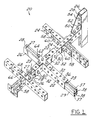
- Figure 1 is a perspective view of a number of possible connections between the various framing members of the inventive system.
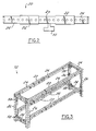
- Figure 2 is a highly schematic view showing one application of the inventive system.
- Figure 3 is a perspective view showing other applications of the inventive system.
- Figure 4 is a perspective view showing an alternative fastener member according to the present invention.
- Figure 5 is a perspective view of the components of the alternative fastener.
- Figure 6 is a cross-sectional view of the initial positioning of the alternative fastener member.
- Figure 7 shows a step subsequent to that shown in Figure 6.
- FIG. 1 An inventive framing system 20 is illustrated in Figure 1 incorporating a large closed tubular member 22, which is rectangular.
- Large closed tubular member 22 has four closed sides, defining an inner peripheral bore 23 which is greater in dimension than the outer dimensions of a smaller closed tubular member 24.
- Small closed tubular member 24 may be attached to one end of large closed tubular member 22, while an open channel member 26 may be attached to the other end of large closed tubular member 22.
- open channel member 26 incorporates two lips 27 extending laterally inwardly to define a channel 28.
- Channel 28 may receive a bolt to attach a support member, or a member to be supported, to open channel member 26.
- the location of the bolt within channel 28 is infinitely adjustable such that the location of the support/supported member is also infinitely adjustable.
- the basic bolt and channel configurations are well known in the art.
- a bolt 30 can extend through mating bolt holes 32 in large and small closed tubular members 22 and 24 to secure the two at any one of several incremental positions.
- the bolt holes 32 on the small closed tubular member 24 are preferably spaced by a distance approximately equal to the distance between bolt holes 32 on the large closed tubular member 22.
- bolt holes 32 may also be formed in closed sides of open channel member 26. Again, the spacing between bolt holes 32 in open channel 26 is preferably approximately equal to the spacing between the bolt holes 32 in closed tubular members 22 and 24.
- a member such as large closed tubular member 22 can act as a bridge or sleeve to connect open channel member 26 to small closed tubular member 24.
- Small closed tubular member 24 may be stronger than open channel member 26. Open channel member 26, however, allows support/supported members to be attached in an infinite number of positions, thus increasing the flexibility of the overall system.
- a bolt 36 can pass through a bolt hole 32 in a large closed channel member 22, and be received in a second type of open channel member 29.
- Second open channel member 29 includes two lips 37 extending laterally inwardly at upper and lower positions to define channels 38 at both upper and lower positions.
- Bolt 36 is frictionally secured within channel 38 at the upper position, as is well known.
- a member to be supported by channel 29 can then be positioned at any of an infinite number of positions from the lower channel 38.
- the use of the large closed tubular member 22 allows a secure connection between second open channel member 29 and a support structure.
- a bolt 40 can also pass through bolt opening 32 in large closed channel member 22 and be received within bolt holes 32 in open channel member 26, as shown in the lower left portion of Figure 1. This provides a fixed, secure connection between tubular member 22 and channel 26 at incremental positions.
- a framing elbow 50 may have bolts 52 extending into bolt holes 32 in one framing member, small closed channel member 24 being shown.
- Bolts 54 may also extend into channel 28 on a open channel member 26. In this way, it is relatively easy to define a strong 90° connection between an open channel member 26 and a closed tubular member 24.
- Simple elbows 58 are also shown with bolts 60 extending into bolt holes 32 in both open and closed tubular members. Further, a cross attachment 62 having bolts 64 may extend into bolt holes 32, and channels 28 to secure several framing members of the inventive system 20. Finally, member 66 may receive bolt 68 which attach three framing members together simply and quickly.
- Figure 1 is an imaginary view developed to show some possibilities of system 20.
- the main features of the present invention relate to its versatility, rather than any particular configuration.
- a small closed tubular member 24 can extend through a great distance, such as along a ceiling in an industrial environment.
- a large closed tubular member 22 can bridge a connection between small closed tubular member 24 and an open channel member, such as open channel member 29.
- Large closed tubular member 22 thus provides a sleeve to securely connect small closed tubular portions 24 to open channel member 29.
- the connection is simple and strong.
- a member 70 may now be hung from open channel member 29 at any of an infinite number of positions along the length of channel 29.
- system 20 provides a strong simple system which allows infinite adjustment in areas where members are to be attached.
- Figure 3 shows additional components of the system 20.
- cross sides are configured of small closed tubular members 24 while side uprights are formed of open channel members 26.
- the cross members are formed of two small closed tubular members 24 with a large closed tubular member section 22 acting as a sleeve between the two smaller closed tubular member sections 24.
- the overall length of the cross members can be incrementally adjusted by telescopically adjusting the members.
- the height of the cross members formed of the closed tubular members 24 can be infinitely adjusted within channel 28 in open channel members 26.
- the above-disclosed structures are not meant to be limiting.
- the present invention can be utilized in any number of configurations.
- racks, shelvings, trapeze hangers, cable tray supports, equipment stands, boat stands, seismic supports, truck racks, structural mezzanine supports, adjustable pipe supports, lighting supports, jack stands, cable racks, conveyor stands and other uses readily are envisioned.
- the inventive features of this invention extend more towards the versatility that flows from the inventive system which allows open channel members to be readily attached to closed tubular members.
- the small closed tubular members and the open channel members had 4,1275 cm (1 5/8) by 4,1275 cm (1 5/8) outer peripheries.
- the large closed tubular member had a 4,7625 cm (1 7/8) by 4,7625 cm (1 7/8) outer periphery. All of the tubular members were manufactured from 12 gauge (0,2667 cm (.105) wall thickness) low carbon strip steel.
- Bolt holes 32 were preferably 1,42875 cm (9/16") in diameter, and spaced by 4,7625 cm (1 7/8").
- a rivet 78 includes a sleeve 79 and a pin 80.
- Pin 80 forces ears 82 on sleeve 79 outwardly to secure rivet 78 in a bolt hole 32. As shown, this attaches a member such as plate member 76 to a closed tubular member 24.
- rivet 78 can also be used through bolt holes in aligned framing members.
- pin 80 is separate from sleeve 79 and ears 82.
- pin 80 is initially received outwardly of sleeve 79, and ears 82 are initially bent radially inwardly. In this way, ears 82 can move into bolt holes 32 in both plate 76 and closed tubular member 24.
- pin 80 is forced downwardly into sleeve 79 and ears 82 bend radially outwardly. This locks rivet 78 within bolt hole 32, securing plate 76 to closed tubular member 24.
Landscapes
- Engineering & Computer Science (AREA)
- Architecture (AREA)
- General Engineering & Computer Science (AREA)
- Physics & Mathematics (AREA)
- Electromagnetism (AREA)
- Civil Engineering (AREA)
- Structural Engineering (AREA)
- Mechanical Engineering (AREA)
- Mutual Connection Of Rods And Tubes (AREA)
- Separation By Low-Temperature Treatments (AREA)
- Superconductors And Manufacturing Methods Therefor (AREA)
- Devices That Are Associated With Refrigeration Equipment (AREA)
- Paper (AREA)
- Joints Allowing Movement (AREA)
- Joining Of Building Structures In Genera (AREA)
- Supports For Pipes And Cables (AREA)
- Prostheses (AREA)
- Rigid Pipes And Flexible Pipes (AREA)
Claims (12)
- Rahmensystem (20), aufweisend:ein geschlossenes Hohlelement (22) mit insgesamt polygonalem Querschnitt, mit geschlossenen Seiten entlang seines Hauptabschnitts, welcher ein Durchgangsloch (23) definiert, wobei eine der geschlossenen Seiten Bohrungen (32) aufweist;ein innerhalb des geschlossenen Hohlelements (22) aufgenommenes offenes Profilelement (26, 29), welches einen polygonalen Querschnitt mit geschlossenen Seiten entlang seines Hauptabschnitts und eine einzelne offene Seite entlang seines Hauptabschnitts aufweist, die einen Kanal (28, 38) bilden; undein Befestigungselement (36, 40), welches durch eine der Bohrungen (32) des geschlossenen Hohlelements (22) hindurch in den Kanal (28, 38) des offenen Profilelements (25, 29) über dessen offene Seite einsetzbar ist, um das offene Profilelement (26, 29) am geschlossenen Hohlelement (22) derart festzulegen, dass die Position des offenen Profilelements (26, 29) innerhalb des Durchgangslochs (23) im geschlossenen Hohlelement (22) stufenlos verstellbar ist.
- System gemäß Anspruch 1, wobei das offene Profilelement (26) entlang einer seiner geschlossenen Seiten Bohrungen (32) aufweist, und das Befestigungselement (36, 40) durch eine der Bohrungen (32) des geschlossenen Hohlelements (22) und durch eine der Bohrungen (32) des offenen Profilelements (26) hindurch einsteckbar ist, um das offene Profilelement (26) am geschlossenen Hohlelement derart festzulegen, dass die Position des offenen Profilelements (26) innerhalb des Durchgangslochs (23) im geschlossenen Hohlelement (22) schrittweise verstellbar ist.
- System gemäß Anspruch 1 oder 2, wobei das geschlossene Hohlelement (22) und das offene Profilelement (26, 29) einen rechteckigen Querschnitt aufweisen.
- System gemäß einem der Ansprüche 1 bis 3, wobei das Befestigungselement ein Niet (78) mit einem Bolzen (80) ist, welcher eine Mehrzahl von Feststellkeilen (82) radial nach außen drückt.
- System gemäß einem der Ansprüche 1 bis 4 mit einem zusätzlichen geschlossenen Hohlelement (24), wobei das zusätzliche geschlossene Hohlelement (24) ebenfalls einen polygonalen Querschnitt aufweist, und wobei die Außenabmessungen des zusätzlichen geschlossenen Hohlelements (24) und des offenen Profilelements (26, 29) geringer sind als die Innenabmessungen des geschlossenen Hohlelements (22), so dass das geschlossene Hohlelement (22) sowohl das zusätzliche geschlossene Hohlelement (24) als auch das offene Profilelement (26, 29) innerhalb des Durchgangslochs (23) aufnehmen kann, um eine Hülse bereitzustellen, welche die beiden verbindet.
- System gemäß Anspruch 5, wobei Bohrungen (32) entlang der geschlossenen Seiten des zusätzlichen geschlossenen Hohlelements (24) ausgebildet sind und das zusätzliche geschlossene Hohlelement (24) am geschlossenen Hohlelement (22) mittels eines Befestigungsmittels (30) festgelegt ist, welches sich durch eine der Bohrungen (32) im geschlossenen Hohlelement (22) hindurch in eine der Bohrungen (32) im zusätzlichen geschlossenen Hohlelement (24) hineinerstreckt.
- System gemäß Anspruch 6, wobei die Bohrungen (32) im geschlossenen Hohlelement (22), im zusätzlichen geschlossenen Hohlelement (24) und im offenen Profilelement (26, 29) im gleichen Abstand voneinander angeordnet sind.
- System gemäß den Ansprüchen 1 bis 7 mit einem zusätzlichen offenen Profilelement (26, 29), wobei das geschlossene Hohlelement (22) in einem 90°-Winkel bezüglich des zusätzlichen offenen Profilelements (26, 29) an diesem befestigt ist.
- System gemäß Anspruch 8, wobei das zusätzliche offene Profilelement (26, 29) ebenfalls Bohrungen (32) aufweist und die 90°-Winkelverbindung mittels Festlegen eines Knieelements (58) am geschlossenen Hohlelement (22) und am zusätzlichen offenen Profilelement (26, 29) mittels durchgehenden Bolzen (40) vorgesehen ist, welche durch die im geschlossenen Hohlelement (22) und die im zusätzlichen offenen Profilelement (26, 29) vorgesehenen Bohrungen (32) hindurchgehen.
- System gemäß Anspruch 8, wobei die 90°-Winkelverbindung durch Festlegen eines 90°-Winkelstücks (50) am geschlossenen Hohlelement (22) mittels eines Bolzens (40) vorgesehen ist, welcher durch eine der Bohrungen (32) im geschlossenen Hohlelement (22) hindurchgesteckt wird, und das Winkelstück (50) am zusätzlichen offenen Profilelement (26, 29) mittels eines durchgehenden Bolzens (40) festgelegt wird, der in dessen Kanal (28) hineingesteckt wird.
- System gemäß Anspruch 8, wobei die 90°-Winkelverbindung Elemente aufweist, welche sich in jede von vier 90°-Richtungen von einem mittigen, kreuzförmigen Befestigungselement voneinander aus erstrecken.
- System gemäß Anspruch 11, wobei das kreuzförmige Befestigungselement am geschlossenen Hohlelement (22) festgelegt ist und ebenfalls an den Elementen festgelegt ist, welche sich im 90°-Winkel vom geschlossenen Hohlelement (22) aus erstrecken.
Applications Claiming Priority (3)
| Application Number | Priority Date | Filing Date | Title |
|---|---|---|---|
| US876248 | 1986-06-19 | ||
| US07/876,248 US5188479A (en) | 1992-04-30 | 1992-04-30 | Tubular framing system |
| PCT/US1993/000506 WO1993022597A1 (en) | 1992-04-30 | 1993-01-21 | Tubular framing system |
Publications (3)
| Publication Number | Publication Date |
|---|---|
| EP0640197A1 EP0640197A1 (de) | 1995-03-01 |
| EP0640197A4 EP0640197A4 (de) | 1995-08-09 |
| EP0640197B1 true EP0640197B1 (de) | 2001-05-30 |
Family
ID=25367273
Family Applications (1)
| Application Number | Title | Priority Date | Filing Date |
|---|---|---|---|
| EP93903601A Expired - Lifetime EP0640197B1 (de) | 1992-04-30 | 1993-01-21 | Rohrförmiges rahmensystem |
Country Status (8)
| Country | Link |
|---|---|
| US (2) | US5188479A (de) |
| EP (1) | EP0640197B1 (de) |
| AT (1) | ATE201758T1 (de) |
| AU (1) | AU687729B2 (de) |
| CA (1) | CA2088857C (de) |
| DE (1) | DE69330273T2 (de) |
| MX (1) | MX9300828A (de) |
| WO (1) | WO1993022597A1 (de) |
Cited By (1)
| Publication number | Priority date | Publication date | Assignee | Title |
|---|---|---|---|---|
| US10428522B2 (en) * | 2017-09-25 | 2019-10-01 | Pravin Nanayakkara | Construction metallic trapezoidal systems |
Families Citing this family (44)
| Publication number | Priority date | Publication date | Assignee | Title |
|---|---|---|---|---|
| US6062396A (en) * | 1995-09-29 | 2000-05-16 | Ultimate Support Systems, Inc. | Integrated vehicle display system |
| US5921334A (en) * | 1996-12-20 | 1999-07-13 | Al-Dokhi; Mansour Bandar | Highway generator |
| US6375135B1 (en) | 1998-01-15 | 2002-04-23 | Ultimate Support Systems, Inc. | High strength engineered collapsible tripod |
| AU5643300A (en) * | 1999-05-03 | 2000-11-17 | Robert Mark Clegg | An adjustable framework for containing objects |
| US20050145662A1 (en) * | 1999-06-18 | 2005-07-07 | Let's Go Aero, Inc. | Equipment and cargo carrier systems |
| US6846140B2 (en) * | 2000-10-25 | 2005-01-25 | Nissan Design America, Inc. | Flexible truck bed tie-down system |
| US6712568B2 (en) | 2000-10-25 | 2004-03-30 | Nissan Technical Center North America, Inc. | Tie-down system with deformation region |
| EP1232903B1 (de) * | 2001-02-14 | 2003-09-24 | Sörensen Hydraulik Zweigniederlassung, Ulfborg, Filial af Sörensen Hydraulik GmbH, Tyskland | Einrichtung zur Befestigung von Ladebordwandsystemen am Chassis-Rahmensystem von Anhängern, Sattelaufliegern und Fahrzeugen |
| EP1395717A1 (de) | 2001-06-15 | 2004-03-10 | Kimball International Inc. | Wandpaneelsystem, das sich vom boden bis zur decke erstreckt |
| FR2838355A1 (fr) * | 2002-04-12 | 2003-10-17 | Didier Philippe Torres | Dispositif de realisation d'une cible pour la pratique de jeux d'adresse au moyen d'un ballon |
| US20050034378A1 (en) * | 2002-06-06 | 2005-02-17 | Underwood Robert A. | Partition system |
| US6827531B2 (en) * | 2003-01-03 | 2004-12-07 | Nissan Technical Center North America, Inc. | Track slot fastener |
| US7175377B2 (en) * | 2003-01-03 | 2007-02-13 | Nissan Technical Center North America, Inc. | Track slot fastener |
| US7562951B2 (en) * | 2004-03-19 | 2009-07-21 | Windquest Companies, Inc. | Wall cabinet system |
| US20080229699A1 (en) * | 2007-03-21 | 2008-09-25 | Unistrut International Corporation | Fittings for metal framing |
| US7874774B2 (en) * | 2007-09-20 | 2011-01-25 | Nissan North America, Inc. | Vehicle cargo arrangement |
| US20090246741A1 (en) * | 2008-01-09 | 2009-10-01 | Mark Soodeen | Modular flight control structure |
| US20100294906A1 (en) * | 2009-05-22 | 2010-11-25 | Jervis B. Webb Company | Universal framing channel mounting bracket |
| US8562241B2 (en) * | 2009-05-22 | 2013-10-22 | Jervis B. Webb Company | Universal framing channel mounting bracket |
| ES2358942B1 (es) * | 2009-05-22 | 2012-05-25 | Daniel Tecedor Rotaeche | Entreplanta ajustable. |
| US8371198B2 (en) * | 2009-08-20 | 2013-02-12 | Joseph Babine | Table saw fence engagement and blade guard apparatus |
| CN103780197A (zh) * | 2012-10-23 | 2014-05-07 | 富昱能源科技(昆山)有限公司 | 太阳能模组支架组合 |
| US8925718B2 (en) | 2013-03-07 | 2015-01-06 | Engineeringology Inc. | Modular support system |
| ITVA20130018A1 (it) * | 2013-03-19 | 2014-09-20 | Mario Sergio Arnoldi | Square technology universal system |
| US9777908B1 (en) | 2014-02-27 | 2017-10-03 | Amazon Technologies, Inc. | Strut channel recessed lighting fixture |
| US20150276092A1 (en) * | 2014-03-27 | 2015-10-01 | Unistrut International Corporation | Enhanced corrosion resistant channels, fittings and fasteners |
| US10274124B2 (en) * | 2014-09-19 | 2019-04-30 | Robert Bosch Gmbh | Framework assembly and hydraulic system having the same |
| US9631357B2 (en) * | 2015-02-26 | 2017-04-25 | Allen Brb, Llc | Systems and methods for fabrication and use of brace designs for braced frames |
| USD805881S1 (en) * | 2016-10-13 | 2017-12-26 | Unistrut International Corporation | Heavy duty cantilever bracket |
| USD805375S1 (en) * | 2016-10-13 | 2017-12-19 | Unistrut International Corporation | Heavy duty cantilever bracket |
| WO2018080619A1 (en) * | 2016-10-28 | 2018-05-03 | Bull Moose Tube Company | Hss connector with swaged interface |
| US10427617B2 (en) * | 2016-12-19 | 2019-10-01 | Cnh Industrial America Llc | Adjustable interface mount for a work vehicle |
| DE102017201656B4 (de) | 2017-02-02 | 2022-01-05 | Norbert Huber | Bausatz zum Aufbau einer Halterung für Rohrleitungen |
| US10260235B1 (en) * | 2017-09-25 | 2019-04-16 | Pravin Nanayakkara | Construction metallic trapezoidal systems |
| US10538906B2 (en) * | 2017-09-26 | 2020-01-21 | Pravin Nanayakkara | Composite floor joist |
| FR3075233B1 (fr) * | 2017-12-15 | 2020-01-10 | Areva Np | Dispositif et procede d'ancrage d'un equipement a une structure de genie civil |
| WO2019241472A1 (en) * | 2018-06-13 | 2019-12-19 | Kpi Concepts, Inc. | Adjustable zero-clearance shelving bracket and shelf assembly |
| CN108824796A (zh) * | 2018-06-27 | 2018-11-16 | 苏州市蓄动源自动化科技有限公司 | 一种建筑施工用钢管固定装置 |
| CN212453075U (zh) * | 2020-06-17 | 2021-02-02 | 国家建筑材料展贸中心 | 一种钢结构装配式建筑的梁柱节点结构 |
| US11447340B1 (en) * | 2021-03-18 | 2022-09-20 | Osgood Industries, Llc | Modular frame interface |
| US11511900B2 (en) | 2021-03-18 | 2022-11-29 | Osgood Industries, Llc | Adjustable frame mount for process unit |
| US20230257990A1 (en) * | 2022-02-14 | 2023-08-17 | MDM Enterprises, Inc. | Construction Tie for Securing U-Channels Vertically in Columns |
| US20240049679A1 (en) * | 2022-08-12 | 2024-02-15 | EZwhelp, Inc. | Rail connectors and spacers for animal whelping containers |
| US20250198151A1 (en) * | 2023-12-15 | 2025-06-19 | Simpson Strong-Tie Company Inc. | Box beam adjustable support systems |
Family Cites Families (15)
| Publication number | Priority date | Publication date | Assignee | Title |
|---|---|---|---|---|
| CA699696A (en) * | 1964-12-08 | A. D. Mackie William | Coupling device | |
| US1895259A (en) * | 1928-07-11 | 1933-01-24 | Motorenfabrik Deutz Ag | Cam operating means |
| US1850118A (en) * | 1928-10-15 | 1932-03-22 | Alfred M Meyers | Building construction |
| US1859259A (en) * | 1929-07-08 | 1932-05-17 | Chamberlain | Electrical wiring conduit |
| NL82706C (de) * | 1951-04-03 | |||
| FR1386323A (fr) * | 1963-11-15 | 1965-01-22 | Vallourec | Structures démontables en profilés perforés |
| US3462021A (en) * | 1968-01-29 | 1969-08-19 | Eugene E Hawke | Load-resisting structures made of thin-walled,square tubing and connected with novel square,non-twisting couplings |
| US3511000A (en) * | 1968-08-08 | 1970-05-12 | Henry P C Keuls | Interlocking hollow building blocks |
| US4069638A (en) * | 1974-06-05 | 1978-01-24 | Scanovator Ab | Structure of lightweight bars and connector means therefore |
| US4261470A (en) * | 1979-05-01 | 1981-04-14 | Dolan Donald L | Collapsible rack |
| GB2060116B (en) * | 1979-10-12 | 1983-03-16 | Linvar Ltd | Structural joints |
| US4784552A (en) * | 1982-02-01 | 1988-11-15 | Unistrut International Corp. | Nuts for channeled structural members |
| US4662532A (en) * | 1985-11-04 | 1987-05-05 | Steel King Industries, Inc. | Foldable container |
| AU2875089A (en) * | 1988-01-22 | 1989-07-27 | Gerald Michale O'Brien | A support structure for cable joining jigs |
| CH681383A5 (de) * | 1990-04-11 | 1993-03-15 | Alusuisse Lonza Services Ag |
-
1992
- 1992-04-30 US US07/876,248 patent/US5188479A/en not_active Expired - Lifetime
-
1993
- 1993-01-21 EP EP93903601A patent/EP0640197B1/de not_active Expired - Lifetime
- 1993-01-21 AT AT93903601T patent/ATE201758T1/de active
- 1993-01-21 DE DE69330273T patent/DE69330273T2/de not_active Expired - Lifetime
- 1993-01-21 US US08/006,561 patent/US5297888A/en not_active Expired - Lifetime
- 1993-01-21 AU AU34805/93A patent/AU687729B2/en not_active Expired
- 1993-01-21 WO PCT/US1993/000506 patent/WO1993022597A1/en not_active Ceased
- 1993-02-05 CA CA002088857A patent/CA2088857C/en not_active Expired - Lifetime
- 1993-02-16 MX MX9300828A patent/MX9300828A/es unknown
Cited By (1)
| Publication number | Priority date | Publication date | Assignee | Title |
|---|---|---|---|---|
| US10428522B2 (en) * | 2017-09-25 | 2019-10-01 | Pravin Nanayakkara | Construction metallic trapezoidal systems |
Also Published As
| Publication number | Publication date |
|---|---|
| CA2088857C (en) | 2004-08-17 |
| EP0640197A4 (de) | 1995-08-09 |
| AU3480593A (en) | 1993-11-29 |
| DE69330273D1 (de) | 2001-07-05 |
| AU687729B2 (en) | 1998-03-05 |
| DE69330273T2 (de) | 2002-04-18 |
| WO1993022597A1 (en) | 1993-11-11 |
| US5297888A (en) | 1994-03-29 |
| ATE201758T1 (de) | 2001-06-15 |
| MX9300828A (es) | 1993-10-01 |
| US5188479A (en) | 1993-02-23 |
| HK1013679A1 (en) | 1999-09-03 |
| CA2088857A1 (en) | 1993-10-31 |
| EP0640197A1 (de) | 1995-03-01 |
Similar Documents
| Publication | Publication Date | Title |
|---|---|---|
| US5188479A (en) | Tubular framing system | |
| US9464749B2 (en) | Seismic bracing assembly | |
| EP1185762B1 (de) | Montagesystem und rückhalteclip | |
| US5873556A (en) | Adjustable drop ceiling fixture support | |
| US4078752A (en) | Conduit support and seismic bracing system | |
| US6243996B1 (en) | Adjustable truss for mating seam of multi-section manufactured home | |
| US7659865B2 (en) | Adjustable fast set antenna frame | |
| US6609343B1 (en) | Open-web-joist load-support system | |
| US4805863A (en) | Brace and shelf support assembly | |
| US6430887B1 (en) | Hinge assembly for a truss | |
| AU728573B1 (en) | Safety line anchorage methods and apparatus | |
| US4408922A (en) | Coupler | |
| US20080135691A1 (en) | Securing system | |
| US20030074849A1 (en) | Slotted metal stud | |
| HK1013679B (en) | Tubular framing system | |
| GB2353320A (en) | Telescopic scaffold board | |
| JPH0717904Y2 (ja) | パイプ固定具 | |
| CN223398491U (zh) | 一种建筑工程施工场地用组装式警示栏 | |
| CN220061619U (zh) | 索膜与照明构件的间距可调式连接装置 | |
| US20260076358A1 (en) | Treestand Platform extension | |
| JP2753187B2 (ja) | 支持パイプ接続構造 | |
| US20250002297A1 (en) | System and method for the construction of a multi-planar lightweight integrated post and handrail assembly | |
| KR200171839Y1 (ko) | 범용 브래킷 구조 | |
| JPH0448271Y2 (de) | ||
| KR200222080Y1 (ko) | 지중전력구의 방재트로후 받침 행거 |
Legal Events
| Date | Code | Title | Description |
|---|---|---|---|
| PUAI | Public reference made under article 153(3) epc to a published international application that has entered the european phase |
Free format text: ORIGINAL CODE: 0009012 |
|
| 17P | Request for examination filed |
Effective date: 19941130 |
|
| AK | Designated contracting states |
Kind code of ref document: A1 Designated state(s): AT DE GB |
|
| A4 | Supplementary search report drawn up and despatched | ||
| AK | Designated contracting states |
Kind code of ref document: A4 Designated state(s): AT DE GB |
|
| 17Q | First examination report despatched |
Effective date: 19970128 |
|
| GRAG | Despatch of communication of intention to grant |
Free format text: ORIGINAL CODE: EPIDOS AGRA |
|
| GRAG | Despatch of communication of intention to grant |
Free format text: ORIGINAL CODE: EPIDOS AGRA |
|
| GRAH | Despatch of communication of intention to grant a patent |
Free format text: ORIGINAL CODE: EPIDOS IGRA |
|
| GRAH | Despatch of communication of intention to grant a patent |
Free format text: ORIGINAL CODE: EPIDOS IGRA |
|
| GRAA | (expected) grant |
Free format text: ORIGINAL CODE: 0009210 |
|
| AK | Designated contracting states |
Kind code of ref document: B1 Designated state(s): AT DE GB |
|
| REF | Corresponds to: |
Ref document number: 201758 Country of ref document: AT Date of ref document: 20010615 Kind code of ref document: T |
|
| REF | Corresponds to: |
Ref document number: 69330273 Country of ref document: DE Date of ref document: 20010705 |
|
| REG | Reference to a national code |
Ref country code: GB Ref legal event code: IF02 |
|
| PLBE | No opposition filed within time limit |
Free format text: ORIGINAL CODE: 0009261 |
|
| STAA | Information on the status of an ep patent application or granted ep patent |
Free format text: STATUS: NO OPPOSITION FILED WITHIN TIME LIMIT |
|
| 26N | No opposition filed | ||
| REG | Reference to a national code |
Ref country code: GB Ref legal event code: 732E |
|
| PGFP | Annual fee paid to national office [announced via postgrant information from national office to epo] |
Ref country code: DE Payment date: 20120127 Year of fee payment: 20 |
|
| PGFP | Annual fee paid to national office [announced via postgrant information from national office to epo] |
Ref country code: GB Payment date: 20120126 Year of fee payment: 20 |
|
| REG | Reference to a national code |
Ref country code: DE Ref legal event code: R071 Ref document number: 69330273 Country of ref document: DE |
|
| REG | Reference to a national code |
Ref country code: GB Ref legal event code: PE20 Expiry date: 20130120 |
|
| REG | Reference to a national code |
Ref country code: AT Ref legal event code: MK07 Ref document number: 201758 Country of ref document: AT Kind code of ref document: T Effective date: 20130121 |
|
| PGFP | Annual fee paid to national office [announced via postgrant information from national office to epo] |
Ref country code: AT Payment date: 20120103 Year of fee payment: 20 |
|
| PG25 | Lapsed in a contracting state [announced via postgrant information from national office to epo] |
Ref country code: DE Free format text: LAPSE BECAUSE OF EXPIRATION OF PROTECTION Effective date: 20130122 Ref country code: GB Free format text: LAPSE BECAUSE OF EXPIRATION OF PROTECTION Effective date: 20130120 |