EP0640275A2 - Schneidkopf für Fadenschneider - Google Patents
Schneidkopf für Fadenschneider Download PDFInfo
- Publication number
- EP0640275A2 EP0640275A2 EP94117568A EP94117568A EP0640275A2 EP 0640275 A2 EP0640275 A2 EP 0640275A2 EP 94117568 A EP94117568 A EP 94117568A EP 94117568 A EP94117568 A EP 94117568A EP 0640275 A2 EP0640275 A2 EP 0640275A2
- Authority
- EP
- European Patent Office
- Prior art keywords
- cord
- casing
- bobbin
- cutting head
- teeth
- Prior art date
- Legal status (The legal status is an assumption and is not a legal conclusion. Google has not performed a legal analysis and makes no representation as to the accuracy of the status listed.)
- Withdrawn
Links
Images






Classifications
-
- A—HUMAN NECESSITIES
- A01—AGRICULTURE; FORESTRY; ANIMAL HUSBANDRY; HUNTING; TRAPPING; FISHING
- A01D—HARVESTING; MOWING
- A01D34/00—Mowers; Mowing apparatus of harvesters
- A01D34/01—Mowers; Mowing apparatus of harvesters characterised by features relating to the type of cutting apparatus
- A01D34/412—Mowers; Mowing apparatus of harvesters characterised by features relating to the type of cutting apparatus having rotating cutters
- A01D34/416—Flexible line cutters
- A01D34/4161—Means for feeding cutter line
Definitions
- the present invention relates generally to a cutting head for a cord type mower. More particularly, the present invention relates to a cord feeding system for extending a cord wound on a bobbin in a rotary casing to a length necessary for mowing.
- the so called tap-and-go type and automatic type cutting heads are popular.
- the cord is fed the required length by releasing an interlock between a bobbin and a rotary casing.
- the interlock is released either by hitting or strongly pressing the rotary casing against the ground.
- This type of cutting head is disclosed in, for example, Japanese Utility Model Publication No. 2-16595, Japanese Patent Publication No. 2-26922, US Patent No. 4161820, US Patent No. 4183138, and US Patent No. 4189833.
- the tap-and-go type has the advantage that the operator can freely set the cord length according to the state of the material (such as grass) being cut.
- the state of the material such as grass
- grass when grass is soft, it is possible to improve the operation efficiency by extending the cord length which permits to the cutter to mow at a faster rate.
- grass when grass is hard, it is possible to ensure that the grass is cut by setting the cord length to a relatively small value, which increases the cutting force of the cord. Therefore, some operators prefer the advantage of optionally setting the cord length according to the situation to the labour saving advantages of the automatic feeding devices.
- An automatic type feed mechanism automatically extends the cord after it has been worn to a predetermined length. Because the extension length depends on the characteristics of the elastic body and heavy bob set in the rotary casing, it is limited to a predetermined range. Therefore, to change the extension length, the elastic body and heavy bob should be changed. However, it is very troublesome to change the parts in accordance to the type of operation. Therefore, the cord length is normally preset to an average length required during operation in a variety of situations.
- the automatic-type cutting head does not require hitting by the operator and is therefore easier to operate.
- the operator cannot optionally select the cord length, it is impossible to extend the cord longer than the set length or keep the cord shorter than the set length.
- the tap-and-go type and the automatic type each have their own features.
- each of the features appears as both an advantage or disadvantage. Because the tap-and-go type allows the operator to optionally select the cord length, it easier for professional operators to use because it operates more efficiently.
- the tap-and-go type requires the operator to always pay attention to the cord length and also requires that the rotary casing be hit when the remaining cord becomes short. Therefore, during prolonged mowing, this type gives a larger burden and physical load to the operator. Thus, the request (or demand) for the automatic type has recently been increasing in the professional market.
- a cutting head for a cord-type mower having a motor or engine for driving the cutting head comprises:
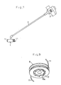
- the cord type mower has a cutting head 1, an engine 3, and a shaft tube 2.
- the shaft tube 2 connects the head 1 with the engine 3 and transmits the power of the engine 3 to the head 1.
- the head 1 is operated by the engine 3 through the tube 2. The following is the detailed description of the head 1.
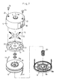
- a rotary casing 4 of the head 1 has a housing 5 and a protective cover 6.
- the casing 4 is connected to a drive shaft (not illustrated) rotatably installed in the tube 2 by a centre bolt 7 at the centre of the housing 5. Therefore, the housing 5 and the cover 6 are rotated together around an axis 7a of the centre bolt 7.
- a bobbin 8 and a control plate 9 coupled to the bobbin 8 are stored in the casing 4 so that they can rotate around the axis 7a independently of the casing 4.
- a pair of cord feed slots 10 are provided on the outer periphery of the housing 5 and are spaced apart by an interval of 180 °.
- the bobbin 8 has upper and lower section and one of two cords 11 is wound about each bobbin section. The end of each cord 11 passes through an associated one of the slots 10 and extends outside the housing 5.
- each drive link 12 is installed in the housing 5 such that they are positioned around the axis 7a at 90 intervals. Each link 12 can move in the radial direction of the housing 5 within the housing.
- a groove is provided in the top surface of the plate 9.
- the groove is composed of eight radial groove sections 13 and eight guide groove sections 14 that connect the radial grooves 13.
- the radial grooves 13 extend generally in the radial direction of the plate 9 and are provided at equal angular intervals about the centre bolt 7. Adjacent radial and guide grooves 13 and 14 cooperate to form an inner step 13a nearer to the centre bolt 7 and an outer step 13b farther from the centre bolt 7.
- a link stud 12a protrudes from the lower surface of each link 12.
- These link studs 12a extend into the plate groove. Thus, they are typically positioned in four of the radial groove sections 13. That is, in every other radial groove.
- Each link 12 is biased in the direction of the axis 7a by a compression coil spring 15 such that the link stud 12a is normally pressed against the step 13a of the groove 13 by the pressure of the spring 15.
- each projection 16 is provided on the top surface of the bobbin 8 at equally spaced intervals.
- Each projection includes a tapered surface 16a which tilts in the same direction as the projection.
- eight projections 17 are provided on the bottom surface of the bobbin 8 at equally spaced intervals.
- the projections 17 thus each include a tapered surface 17a.
- Each projection 16 at the top and each projection 17 at the bottom are installed corresponding to the same angular position in a concentric circle.
- the surfaces 16a and 17a tilt in the opposite direction to each other.
- each tapered recesses 18 are formed on the bottom surface of the plate 9 at equally spaced intervals.
- the recesses 18 each include a tapered surface 18a.
- eight tapered recesses 19 are also formed on the inside bottom surface of the cover 6 at an equally spaced intervals.
- the recesses 19 also each include a tapered surface 19a.
- each tapered recess 18 of the plate 9 and each recess 19 of the cover 6 are arranged along the periphery so that the former are staggered from the latter by 2-ff/16 radians.
- the tapered surface 18 and the surface 19a tilt in the opposite directions.
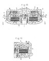
- the bobbin 8 can slide along the axis 7a in the casing 4 and is pressed upward by a compression coil spring 20 supported by the cover 6. As shown in Figs. 2, 5, and 6, the pressure of the spring 20, pushes the projections 16 into the recesses 18 of the plate 9. At the same time, the projections 17 on the bottom surface of the bobbin 8 are separated from the recesses 19 of the cover 6.
- a pair of bores 22 are formed in the upper surface of housing 5 at positions separated by an interval of 1800.
- a pair of holes 23 are formed on the plate 9 such that they are aligned with the bores 22.
- the head 1 has the automatic and tap-and-go feeding functions.
- the plate 9 is rotated therewith due to its engagement with the link stud 12a.
- the bobbin 8 is also rotated due to the fact that the top projections 16 engage the recesses 18 in plate 9.
- the cord 11 which extends through the slot 10 is also rotated to cut grass or the like.
- the cord 11 is wound in a direction that is opposite to the rotational direction of the casing 4.
- the slot 10 rotates together with the casing 4. Therefore, the distal end of the cord 11 follows the rotation of the casing 4.
- the cord 11 is feed into the internal space of the casing 4 a distance equivalent to the distance the bobbin 8 slips relative to the casing 4. Centrifugal force then draws the feed cord 11 outside of the casing through the slot 10.
- the rotational resistance of the casing 4 gradually increases which reduces the speed of the casing 4.
- the centrifugal force working on the link 12 decreases and the link 12 returns toward the axis 7a by the force of the spring 15.
- the stud 12a of the link 12 reaches the stop position of the adjacent groove 13.
- the casing 4 has been rotated a distance of 2 ⁇ /8 radians (45 ° ) relative to the bobbin 8. Then, the plate 9 and the bobbin 8 rotate together with the casing 4 until the cord 11 is again worn due to use.
- the length of the cord 11 to be feed from the slot 10 is normally set to a constant value in this type of automatic feeding.
- the head is used in the tap-and-go mode, it is possible to extend the cord 11 a total distance that is longer than the above set value.
- the cord is feed by hitting the casing 4 against the ground. More specifically in the state shown in Figs. 2, 5, and 6, the casing is hit against the ground while it rotates.
- the impact drives the bobbin 8 against the pressure of the spring 20 as shown in Figs. 10, 11, and 12.
- the bottom projections 17 of the bobbin 8 thus contact the recesses 19 in the cover 6 in an offset manner.
- a part of the tapered surface 17a of the projection 17 contacts a part of the tapered surface 19a of the recess 19.
- the casing 4 and the plate 9 then rotate relative to the bobbin 8 by the amount the bottom projections 17 are offset from the recesses 19. That is 2-ff/16 radians.
- the bobbin 8 again rotates together with the casing 4 and the plate 9. While the bobbin 8 slips relative to the casing 4, the cord 11 is feed a corresponding amount.
- the bobbin 8 Since the spring 20 is compressed by the downward moving bobbin 8 due to the inertia created by the hitting actions, the bobbin 8 is thereafter pushed upward by the action of the spring 20.
- the top projection 16 of the bobbin 8 is thus inserted into the recess 18 of the plate 9 and a part of the surface 16a of the projection 16 contacts a part of the surface 18a of the recess 18.
- the casing 4 and the plate 9 rotate 2-ff/16 radians relative to the bobbin 8 which feeds the cord 11 accordingly.
- the bobbin 8 again rotates together with the casing 4 and the plate 9.
- the cord 11 is extended from the bobbin 8 by the length corresponding to 4-ff/16 radians each time the casing is tapped.
- the head 1 having both the automatic and tap-and-go systems makes it possible to set the length of the cord 11 longer than the extending length set by the automatic system by hitting the casing 4 against the ground as desired.
- the head 1 of the first embodiment has both the automatic and tap-and-go systems, the operator can use both or either one of the two systems according to the situation. Therefore, the disadvantages of the conventional cutting heads having only one of the automatic and tap-and-go system are eliminated. Moreover, this embodiment makes the head compact by arranging both of the systems along the axis 7a.
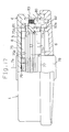
- a bobbin 8 is provided in a rotary casing 4 consisting of a housing 5 and a protective cover 6.
- the bobbin 8 can rotate about and vertically slide along an axis 7a of the casing 4.
- the bobbin 8 is constructed by connecting an upper flange 75 with a lower flange 77 by a cylindrical body (not illustrated.
- Eight teeth 75a-75h are formed on the outer periphery of the upper flange 75 at equally spaced intervals.
- eight teeth 77a-77h are formed on the outer periphery of the lower flange 77 at equally spaced intervals.
- the upper flange teeth 75a-75h are displaced from the lower flange teeth 77a-77h of the lower flange 77 by the angle of 2-ff/16 radians respectively.
- a centre boss 78 is located at the bottom centre of the bobbin 8.
- a compression coil spring 79 is provided in the cylindrical body of the bobbin 8. The top end of the spring 79 contacts the housing 5 and the bottom end of it contacts the lower flange 77. The spring 79 urges the bobbin 8 and the boss 78 downward, and the bottom end of the boss 78 protrudes under the cover 6.
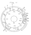
- a swing lever 80 is rotatably supported between the housing 5 and the cover 6 in the casing 4.
- the lever 80 has a first arm 81 at the position approximately corresponding to the height of the upper flange 75 and a second arm 82 at the position slightly lower than the lower flange 77.
- the arms 81 and 82 have approximately equal length and extend in the approximately opposite direction.
- Latching legs 81 a and 82a are protruded at the end of the first arm 81 and that of the second arm 82 respectively so that they are parallel with the axis 7a and approach each other. As shown in Fig. 67, the length of the leg 81 a of the first arm 81 is slightly shorter than the interval between the flanges 75 and 77. The bottom end of the leg 81 a does not contact the lower flange 77.
- the leg 81 a of the first arm 81 is longer and heavier than the leg 82a of the second arm 82, and the moment of inertia of the first arm 81 is larger than that of the second arm 82. Therefore, when centrifugal force acts on the lever 80 due to rotation of the casing 4, the lever 80 is swung so that the first arm 81 separates from the bobbin 8.
- a torsion coil spring 83 is wound on the lever 80. As shown in Fig. 68, the torsion spring 83 urges the lever 80 so that the leg 81 a of the first arm 81 approaches the bobbin 8.
- a partition plate 76 is located between flanges 75 and 77 of the bobbin 8.
- a cord 11 is wound between the upper flange 75 and the plate 76 and between the plate 76 and the lower flange 77 respectively.
- the upper cord 11 is led to a cord feed slot 10 via the leg 81 a of the first arm 81 and extended to the outside of the casing 4.
- the force F1 acts on the lever 80, which swings the lever 80 so that the first arm 81 separates from he bobbin 8 due to rotation of the casing 4.
- a tensile force of the cord 11 tends to further extend the cord 11 outward on the basis of the centrifugal force due to rotation of the casing 4 and the resistance produced when the cord 11 collides with grass.
- the tensile force acts on the lever 80 as the force F2 for swinging the lever 80 so that the first arm 81 approaches the bobbin 8.
- the speed of the casing 4 is kept at the normal speed range (4,000 to 6,000 rpm).
- the sum of the force F2 caused by the tension of the cord 11 and the urging force F3 of the spring 83 is larger than the force F1 caused by the centrifugal force acting on the lever 80. Therefore, as shown in Fig. 15, the lever 80 is held at the position where the first arm 81 engages with the tooth 75a of the upper flange 75. As a result, the casing 4 rotates together with the bobbin 8.
- the cord 11 is not fed from the bobbin 8.
- the leg 82a of the second arm 82 is placed outside the rotational route of the teeth 77a-77h of the lower flange 77.
- the bobbin 8 slips relative to the casing 4.
- the tooth 77b of the lower flange 77 engages with the leg 82a of the second arm 82.
- the bobbin 8 rotates again together with the casing 4. According to relative rotation between the bobbin 8 and the casing 4, the cords 11 are fed outside the casing 4 by the length corresponding to the e difference of rotational angel between the bobbin and the casing 4.
- the bobbin 8 slips relative to the casing 4 similarly to the above mentioned embodiments.
- the end of the first arm 81 engages with the tooth 75h of t he upper flange 75.
- the cords 11 are fed outside the casing 4 by the length corresponding to the difference of rotational angle between the bobbin 8 and the casing 4. therefore, as the cords 11 are worn off, they are automatically fed outside the casing 4 by the length corresponding to the angel of 4-ff/16 radians.
- the head 1 of this embodiment has both the automatic and tap-and-go cord feed functions.
- only one lever 80 is used in the housing 5. however, it is possible to use a plurality of levers 80 corresponding to the number of slots 10.
- a bore 84 is formed on the housing 5 and a stopper pin 85 is inserted into the bore 84.
- the pin 85 has the length from the housing 5 to the first arm 81 of the lever 80.
- the pin 85 engages with the first arm 81 to inhibit the swing of the lever 80 caused by the centrifugal force. Therefore, insertion of the pin 85 into the bore 84 prevents the cords 11 from being automatically fed and allows only the tap-and-go system to operate.
- long stopper pins used for some of the above embodiments so that they can move between the position where their ends stop within the bores of the housing and the position where their ends reach up to the bores of the control plate.
- a remote-controller may be combined with the cutting head to control the position of the pins.
- Only one slot 10 or multiple slots 10 may be provided on the cutting head 1. Then the number of cords 11 can be changed according to the number of the slots 10.
- Eight radial grooves 13 and guide grooves 14 of the plate 9 are used for some of the above embodiments. However, the number of those grooves can be changed in the range of 6 to 12. also, the number of links 12 can be changed according to the number of the grooves. Therefore, the present examples and embodiments are to be considered as illustrative and not restrictive and the invention is not to be limited to the details given herein, but may be modified within the scope of the appended claims.
Landscapes
- Life Sciences & Earth Sciences (AREA)
- Environmental Sciences (AREA)
- Harvester Elements (AREA)
Applications Claiming Priority (3)
| Application Number | Priority Date | Filing Date | Title |
|---|---|---|---|
| JP312500/90 | 1990-11-16 | ||
| JP02312500A JP3113270B2 (ja) | 1990-11-16 | 1990-11-16 | コード型草刈機の刈刃装置におけるコード繰出し機構 |
| EP91310615A EP0486326B1 (de) | 1990-11-16 | 1991-11-18 | Schneidkopf für Fadenschneider |
Related Parent Applications (1)
| Application Number | Title | Priority Date | Filing Date |
|---|---|---|---|
| EP91310615.9 Division | 1991-11-18 |
Publications (2)
| Publication Number | Publication Date |
|---|---|
| EP0640275A2 true EP0640275A2 (de) | 1995-03-01 |
| EP0640275A3 EP0640275A3 (de) | 1995-04-19 |
Family
ID=18029965
Family Applications (4)
| Application Number | Title | Priority Date | Filing Date |
|---|---|---|---|
| EP94117568A Withdrawn EP0640275A3 (de) | 1990-11-16 | 1991-11-18 | Schneidkopf für Fadenschneider. |
| EP94117590A Expired - Lifetime EP0639322B1 (de) | 1990-11-16 | 1991-11-18 | Schneidkopf für Fadenschneider |
| EP91310615A Expired - Lifetime EP0486326B1 (de) | 1990-11-16 | 1991-11-18 | Schneidkopf für Fadenschneider |
| EP94117598A Withdrawn EP0641512A3 (de) | 1990-11-16 | 1991-11-18 | Schneidkopf für Fadenschneider. |
Family Applications After (3)
| Application Number | Title | Priority Date | Filing Date |
|---|---|---|---|
| EP94117590A Expired - Lifetime EP0639322B1 (de) | 1990-11-16 | 1991-11-18 | Schneidkopf für Fadenschneider |
| EP91310615A Expired - Lifetime EP0486326B1 (de) | 1990-11-16 | 1991-11-18 | Schneidkopf für Fadenschneider |
| EP94117598A Withdrawn EP0641512A3 (de) | 1990-11-16 | 1991-11-18 | Schneidkopf für Fadenschneider. |
Country Status (4)
| Country | Link |
|---|---|
| US (7) | US5222301A (de) |
| EP (4) | EP0640275A3 (de) |
| JP (1) | JP3113270B2 (de) |
| AU (2) | AU651395B2 (de) |
Cited By (1)
| Publication number | Priority date | Publication date | Assignee | Title |
|---|---|---|---|---|
| KR20220100587A (ko) * | 2019-10-08 | 2022-07-15 | 가부시키가이샤 기타무라 세이사쿠쇼 | 회전체, 예초기 및 보빈 |
Families Citing this family (46)
| Publication number | Priority date | Publication date | Assignee | Title |
|---|---|---|---|---|
| JP3113270B2 (ja) * | 1990-11-16 | 2000-11-27 | 杉原林機株式会社 | コード型草刈機の刈刃装置におけるコード繰出し機構 |
| JP3167859B2 (ja) * | 1994-04-07 | 2001-05-21 | タナカ工業株式会社 | ナイロンコード型刈払機 |
| US5659960A (en) * | 1996-02-15 | 1997-08-26 | Ryobi North America, Inc. | Line feed configuration for line trimmers |
| US5806192A (en) * | 1996-02-15 | 1998-09-15 | Ryobi North America | Line feed configuration for line trimmers |
| US5758424A (en) * | 1996-08-23 | 1998-06-02 | Iacona; Fernando R. | Head for string trimmer |
| US6148523A (en) * | 1997-02-14 | 2000-11-21 | Ryobi North America, Inc. | Line feed mechanism for a line trimmer |
| IT1294822B1 (it) * | 1997-07-18 | 1999-04-15 | Arnetoli Motor | Testina taglia-erba a filo com mezzi per prevenire l'ingresso di detriti |
| JP3432406B2 (ja) * | 1997-12-12 | 2003-08-04 | 株式会社共立 | 携帯用刈払機 |
| US5906051A (en) * | 1998-04-03 | 1999-05-25 | Nannen; William G. | Height adjustable anti-gouging ground guide system for vegetation trimmer |
| DE19835504C2 (de) * | 1998-08-06 | 2000-12-07 | Stihl Maschf Andreas | Fadenmähkopf |
| JP3982930B2 (ja) * | 1998-11-24 | 2007-09-26 | スターテング工業株式会社 | 刈払機用のロータリカッタ |
| JP4121210B2 (ja) * | 1999-03-16 | 2008-07-23 | スターテング工業株式会社 | 刈払機用のロータリカッタ |
| US6401344B1 (en) | 1999-09-21 | 2002-06-11 | Mark R. Moore | Head for line trimming apparatus |
| US7111403B2 (en) | 1999-09-21 | 2006-09-26 | Moore Mark R | Head for line trimming apparatus |
| GB2359002A (en) * | 2000-09-05 | 2001-08-15 | Black & Decker Inc | Cutting head for a string trimmer |
| CN2459863Y (zh) * | 2000-12-04 | 2001-11-21 | 苏州太湖企业有限公司 | 割草机的自动放线机构 |
| US6952877B2 (en) * | 2003-01-10 | 2005-10-11 | Shindaiwa, Inc. | Vegetation cutting device |
| SE0302176D0 (sv) * | 2003-08-07 | 2003-08-07 | Electrolux Ab | Eyelet for a trimmer head |
| US7412768B2 (en) * | 2004-05-11 | 2008-08-19 | Alliss George E | Invertible trimmer line spool for a vegetation trimmer apparatus |
| ITFI20050192A1 (it) | 2005-09-13 | 2007-03-14 | Arnetoli Motor | Testina tosaerba con mezzi per la protezione del filo di taglio |
| EP1942717B1 (de) * | 2005-11-02 | 2009-10-21 | Fabrizio Arnetoli | Grasmähkopf mit spiralförmigen führungskanälen für die mähschnur |
| US8025249B2 (en) * | 2007-11-16 | 2011-09-27 | Alliss George E | Bi-directional trimmer head spool with curved trimmer line guide |
| US7536792B2 (en) * | 2007-01-03 | 2009-05-26 | Moore Mark R | Head for a rotary line trimmer apparatus |
| USD581753S1 (en) * | 2007-10-30 | 2008-12-02 | Conceptual Marketing & Development, Inc | Combination trimmer and edger |
| CN101932226B (zh) * | 2008-03-05 | 2013-10-30 | 星天具工业株式会社 | 割草机用旋转切割器 |
| ITFI20080097A1 (it) * | 2008-05-15 | 2009-11-16 | Arnetoli Motor Srl | "una testina tosaerba a filo utilizzabile alternativamente su macchine a rotazione destra o sinistra" |
| JP5271433B2 (ja) * | 2011-04-15 | 2013-08-21 | ブイアイブイエンジニアリング株式会社 | 刈払機 |
| CN103875350B (zh) * | 2012-12-20 | 2016-12-28 | 苏州宝时得电动工具有限公司 | 放线机构及打草机 |
| EP2798933B1 (de) * | 2013-05-03 | 2018-07-11 | Black & Decker Inc. | Vorrichtung zum Schneiden von Vegetation |
| CN105075494A (zh) * | 2014-05-08 | 2015-11-25 | 苏州宝时得电动工具有限公司 | 打草机 |
| US10130030B2 (en) * | 2014-05-27 | 2018-11-20 | Mtd Products Inc | Trimmer head |
| JP6053042B2 (ja) * | 2014-08-18 | 2016-12-27 | 株式会社ハートフル・ジャパン | 刈払機のコード自動繰出し機構。 |
| PL3056075T3 (pl) * | 2015-02-16 | 2017-10-31 | Tecomec Srl | Automatyczna głowica przycinarki |
| WO2017147172A1 (en) * | 2016-02-22 | 2017-08-31 | Mtd Products Inc | Multi-mode trimmer head |
| CN105917839B (zh) * | 2016-04-05 | 2018-08-21 | 浙江顶诚工贸有限公司 | 一种手持式割草机的切割器 |
| CN105917840B (zh) * | 2016-04-05 | 2018-08-21 | 浙江顶诚工贸有限公司 | 一种手持式割草机 |
| US10070582B2 (en) | 2016-04-20 | 2018-09-11 | Tti (Macao Commercial Offshore) Limited | String trimmer head |
| US10034422B2 (en) | 2016-06-14 | 2018-07-31 | Black & Decker Inc. | Cutting head for a string trimmer |
| CN108617226A (zh) * | 2017-03-23 | 2018-10-09 | 苏州宝时得电动工具有限公司 | 打草机 |
| US20180220582A1 (en) * | 2017-02-08 | 2018-08-09 | Fred Trombino | Disposable quick-connect cutter head assembly for a rotary trimmer |
| CN207665489U (zh) * | 2017-08-07 | 2018-07-31 | 南京德朔实业有限公司 | 打草头 |
| CN109691318B (zh) * | 2017-10-20 | 2021-06-18 | 南京德朔实业有限公司 | 打草头和用于打草的工具系统 |
| US10939614B2 (en) | 2017-11-03 | 2021-03-09 | Mtd Products Inc | Trimmer head |
| CN110213960B (zh) * | 2018-04-02 | 2022-02-22 | 南京德朔实业有限公司 | 打草机 |
| JP7650893B2 (ja) * | 2020-04-01 | 2025-03-25 | ハスクバーナ・アーベー | トリマーライン供給の制御 |
| US12532806B2 (en) * | 2023-02-14 | 2026-01-27 | Techtronic Cordless Gp | Power tool and compact power feed trimmer head |
Family Cites Families (42)
| Publication number | Priority date | Publication date | Assignee | Title |
|---|---|---|---|---|
| ES461559A1 (es) * | 1976-08-13 | 1978-12-01 | Toro Co | Aparato dosificador de filamento de corte en un dispositivo cortador de vegetacion con filamento flexible. |
| US4104796A (en) * | 1977-07-29 | 1978-08-08 | Sheldon John D | Filament-type trimmer |
| US4161820A (en) * | 1977-10-28 | 1979-07-24 | Weed Eater, Inc. | Apparatus for cutting vegetation |
| US4183138A (en) * | 1978-03-08 | 1980-01-15 | Weed Eater, Inc. | Apparatus for cutting vegetation |
| SE7905502L (sv) * | 1978-06-28 | 1979-12-29 | Stihl Maschf Andreas | Vextskerningsredskap |
| US4189833A (en) * | 1978-08-15 | 1980-02-26 | Weed Eater, Inc. | Apparatus for cutting vegetation |
| JPS575608A (en) * | 1980-06-14 | 1982-01-12 | Komatsu Zenoa Kk | Bush cutter |
| US4483069A (en) * | 1979-08-01 | 1984-11-20 | Emerson Electric Co. | Apparatus for cutting vegetation |
| US4347666A (en) * | 1980-07-25 | 1982-09-07 | Emerson Electric Co. | Apparatus for cutting vegetation |
| US4419822A (en) * | 1981-01-14 | 1983-12-13 | Black & Decker Inc. | Bump-feed trimmer |
| JPS5922484A (ja) * | 1982-07-28 | 1984-02-04 | Hitachi Ltd | 固体撮像装置 |
| US4476632A (en) * | 1982-07-29 | 1984-10-16 | Proulx Raymond E | Multiple flail head for a rotary mower |
| JPS59122032U (ja) * | 1983-02-08 | 1984-08-17 | 株式会社共立 | 草刈機 |
| JPS59216595A (ja) * | 1983-05-24 | 1984-12-06 | Baiorisaac Center:Kk | エポキシドの製造方法 |
| WO1985000160A1 (en) * | 1983-06-27 | 1985-01-17 | Occidental Research Corporation | Process for making titanium metal from titanium ore |
| FR2551039B1 (fr) * | 1983-08-24 | 1987-08-14 | Gay Pierre | Dispositif de devidage automatique d'un ou plusieurs fil(s) consommable(s) sortant d'un boitier tournant |
| JPS6083508A (ja) * | 1983-10-15 | 1985-05-11 | タナカ工業株式会社 | ナイロンコ−ド型刈払機 |
| DE3413336C2 (de) * | 1984-04-09 | 1986-11-20 | Wolf-Geräte GmbH, 5240 Betzdorf | Fadenschneider |
| JPS60171126U (ja) * | 1984-04-20 | 1985-11-13 | 株式会社共立 | 草刈機の刈刃装置 |
| US4702005A (en) * | 1984-06-29 | 1987-10-27 | Pittinger Sr Charles B | Apparatus for cutting vegetation with incremental feeding of cutting filament |
| US4561180A (en) * | 1984-06-29 | 1985-12-31 | Pittinger Sr Charles B | Apparatus for cutting vegetation with incremental feeding of cutting filament |
| US4660286A (en) * | 1984-07-11 | 1987-04-28 | Nylon Line Cutters (Pty.) Ltd. | Apparatus with automatic line feeding |
| US4803539A (en) * | 1985-03-29 | 1989-02-07 | International Business Machines Corporation | Dopant control of metal silicide formation |
| AU578004B2 (en) * | 1985-05-24 | 1988-10-06 | Shingu Shoko Ltd. | Apparatus for cutting grass |
| US4817288A (en) * | 1986-03-25 | 1989-04-04 | Daijo Hirose | Cutting head for cord type mower |
| US4897923A (en) * | 1986-09-17 | 1990-02-06 | White Consolidated Industries, Inc. | Automatic line feed head apparatus for a flexible line trimmer or the like |
| US4823465A (en) * | 1986-12-17 | 1989-04-25 | White Consolidated Industries, Inc. | Line feed mechanism for line trimmers |
| ZA878894B (en) * | 1986-12-17 | 1988-09-28 | White Consolidated Ind Inc | Line feed mechanism for line trimmers |
| GB8709464D0 (en) * | 1987-04-22 | 1987-05-28 | Delany P N | Case & pallet systems |
| AU592679B2 (en) * | 1987-10-28 | 1990-01-18 | White Consolidated Industries, Inc. | Apparatus for cutting vegetation |
| DE3739268A1 (de) * | 1987-11-20 | 1989-06-01 | Stihl Maschf Andreas | Schneidkopf |
| DE3739269A1 (de) * | 1987-11-20 | 1989-06-01 | Stihl Maschf Andreas | Schneidkopf |
| JPH0216595A (ja) * | 1988-07-04 | 1990-01-19 | Nec Corp | プラズマディスプレイ装置 |
| JPH0226922A (ja) * | 1988-07-12 | 1990-01-29 | Toray Ind Inc | 炭素繊維の製造方法 |
| US5020224A (en) * | 1988-07-21 | 1991-06-04 | White Consolidated Industries, Inc. | Semi-automatic string trimmer head |
| JP2802429B2 (ja) * | 1988-12-13 | 1998-09-24 | スターテング工業株式会社 | 刈払機用ロータリカッタ |
| DE3916525A1 (de) * | 1989-05-20 | 1990-11-22 | Stihl Maschf Andreas | Schneidkopf |
| DE3922339C1 (de) * | 1989-07-07 | 1990-10-18 | Fa. Andreas Stihl, 7050 Waiblingen, De | |
| GB8920498D0 (en) * | 1989-09-11 | 1989-10-25 | Black & Decker Inc | Improvements in or relating to vegetation cutters |
| EP0467006B1 (de) * | 1989-10-30 | 1995-01-18 | Arnetoli Motor Di Arnetoli Fabrizio | Vorrichtung zum radialen zentrifugalen Zuführen der Fäden des Schneidkopfes von Fadenschneider oder dergleichen |
| US5311665A (en) * | 1990-11-16 | 1994-05-17 | Diatop Corporation | Cutting head for a cord type mower |
| JP3113270B2 (ja) * | 1990-11-16 | 2000-11-27 | 杉原林機株式会社 | コード型草刈機の刈刃装置におけるコード繰出し機構 |
-
1990
- 1990-11-16 JP JP02312500A patent/JP3113270B2/ja not_active Expired - Lifetime
-
1991
- 1991-11-15 AU AU87880/91A patent/AU651395B2/en not_active Ceased
- 1991-11-15 US US07/792,788 patent/US5222301A/en not_active Expired - Lifetime
- 1991-11-18 EP EP94117568A patent/EP0640275A3/de not_active Withdrawn
- 1991-11-18 EP EP94117590A patent/EP0639322B1/de not_active Expired - Lifetime
- 1991-11-18 EP EP91310615A patent/EP0486326B1/de not_active Expired - Lifetime
- 1991-11-18 EP EP94117598A patent/EP0641512A3/de not_active Withdrawn
-
1992
- 1992-12-29 US US07/998,787 patent/US5293692A/en not_active Expired - Fee Related
- 1992-12-29 US US07/998,567 patent/US5293691A/en not_active Expired - Fee Related
- 1992-12-30 US US07/998,420 patent/US5295306A/en not_active Expired - Fee Related
-
1994
- 1994-03-04 US US08/206,253 patent/US5522140A/en not_active Expired - Fee Related
- 1994-03-04 US US08/206,903 patent/US5522141A/en not_active Expired - Fee Related
- 1994-03-04 US US08/206,038 patent/US5526572A/en not_active Expired - Fee Related
- 1994-10-17 AU AU75859/94A patent/AU668322B2/en not_active Ceased
Cited By (2)
| Publication number | Priority date | Publication date | Assignee | Title |
|---|---|---|---|---|
| KR20220100587A (ko) * | 2019-10-08 | 2022-07-15 | 가부시키가이샤 기타무라 세이사쿠쇼 | 회전체, 예초기 및 보빈 |
| US12342753B2 (en) | 2019-10-08 | 2025-07-01 | Kabushiki Kaisha Kitamura Seisakusho | Rotator, brush cutter, and bobbin |
Also Published As
| Publication number | Publication date |
|---|---|
| EP0639322A2 (de) | 1995-02-22 |
| US5222301A (en) | 1993-06-29 |
| AU651395B2 (en) | 1994-07-21 |
| EP0641512A3 (de) | 1995-04-19 |
| EP0639322A3 (de) | 1995-04-19 |
| US5295306A (en) | 1994-03-22 |
| AU8788091A (en) | 1992-05-21 |
| US5293691A (en) | 1994-03-15 |
| EP0640275A3 (de) | 1995-04-19 |
| EP0486326A3 (en) | 1993-07-21 |
| US5522141A (en) | 1996-06-04 |
| AU7585994A (en) | 1994-12-22 |
| EP0641512A2 (de) | 1995-03-08 |
| JPH04183316A (ja) | 1992-06-30 |
| US5526572A (en) | 1996-06-18 |
| AU668322B2 (en) | 1996-04-26 |
| EP0639322B1 (de) | 1999-02-24 |
| EP0486326B1 (de) | 1996-05-01 |
| US5522140A (en) | 1996-06-04 |
| EP0486326A2 (de) | 1992-05-20 |
| US5293692A (en) | 1994-03-15 |
| JP3113270B2 (ja) | 2000-11-27 |
Similar Documents
| Publication | Publication Date | Title |
|---|---|---|
| EP0640275A2 (de) | Schneidkopf für Fadenschneider | |
| US5311665A (en) | Cutting head for a cord type mower | |
| CN112088639B (zh) | 打草机 | |
| US5765287A (en) | Cutting head for nylon-cord type mowers | |
| US20190185289A1 (en) | String trimmer head with curved trimmer line guide | |
| US11412656B2 (en) | Trimmer head with improved line release feature | |
| EP0618852B1 (de) | Automatische zufuhr des schneidkopffadens | |
| EP3205200B1 (de) | Trimmerkopf mit einer schnurkartusche | |
| EP0585720B1 (de) | Mittel zum Zuführen des Fadens für Schneidkopf | |
| CN221748964U (zh) | 线式修剪机组件和与其一起使用的修剪机头 | |
| US20230397527A1 (en) | String trimmer head and string trimmer | |
| JP4995563B2 (ja) | 刈払い機用ロータリカッタ | |
| EP4353066A1 (de) | Fadenschneiderkopf | |
| JP5913329B2 (ja) | 草刈機用回転刃およびこれを用いた草刈機 | |
| EP0880882A1 (de) | Mittel zum Zuführen des Fadens für Faden-Schneidkopf | |
| CN111096140B (zh) | 打草机 |
Legal Events
| Date | Code | Title | Description |
|---|---|---|---|
| PUAI | Public reference made under article 153(3) epc to a published international application that has entered the european phase |
Free format text: ORIGINAL CODE: 0009012 |
|
| 17P | Request for examination filed |
Effective date: 19941118 |
|
| AC | Divisional application: reference to earlier application |
Ref document number: 486326 Country of ref document: EP |
|
| AK | Designated contracting states |
Kind code of ref document: A2 Designated state(s): FR IT |
|
| PUAL | Search report despatched |
Free format text: ORIGINAL CODE: 0009013 |
|
| AK | Designated contracting states |
Kind code of ref document: A3 Designated state(s): FR IT |
|
| 17Q | First examination report despatched |
Effective date: 19970902 |
|
| GRAG | Despatch of communication of intention to grant |
Free format text: ORIGINAL CODE: EPIDOS AGRA |
|
| STAA | Information on the status of an ep patent application or granted ep patent |
Free format text: STATUS: THE APPLICATION HAS BEEN WITHDRAWN |
|
| 18W | Application withdrawn |
Withdrawal date: 19980912 |