EP0640278A1 - Dispositif de dosage pour appliquer une couche de sol de recouvrement sur du compost pour cultiver des champignons ou analogues - Google Patents
Dispositif de dosage pour appliquer une couche de sol de recouvrement sur du compost pour cultiver des champignons ou analogues Download PDFInfo
- Publication number
- EP0640278A1 EP0640278A1 EP19940202228 EP94202228A EP0640278A1 EP 0640278 A1 EP0640278 A1 EP 0640278A1 EP 19940202228 EP19940202228 EP 19940202228 EP 94202228 A EP94202228 A EP 94202228A EP 0640278 A1 EP0640278 A1 EP 0640278A1
- Authority
- EP
- European Patent Office
- Prior art keywords
- shaft
- blades
- hopper
- ejection
- metering device
- Prior art date
- Legal status (The legal status is an assumption and is not a legal conclusion. Google has not performed a legal analysis and makes no representation as to the accuracy of the status listed.)
- Withdrawn
Links
- 239000002689 soil Substances 0.000 title claims abstract description 23
- 239000002361 compost Substances 0.000 title claims abstract description 10
- 235000001674 Agaricus brunnescens Nutrition 0.000 title claims abstract description 7
- 230000001105 regulatory effect Effects 0.000 claims description 11
- 238000010276 construction Methods 0.000 description 3
- 239000000463 material Substances 0.000 description 2
- 230000005540 biological transmission Effects 0.000 description 1
- 230000015572 biosynthetic process Effects 0.000 description 1
- 238000006073 displacement reaction Methods 0.000 description 1
- 230000000694 effects Effects 0.000 description 1
- 238000002156 mixing Methods 0.000 description 1
- 238000007788 roughening Methods 0.000 description 1
- 230000007704 transition Effects 0.000 description 1
- 238000009966 trimming Methods 0.000 description 1
Images


Classifications
-
- A—HUMAN NECESSITIES
- A01—AGRICULTURE; FORESTRY; ANIMAL HUSBANDRY; HUNTING; TRAPPING; FISHING
- A01G—HORTICULTURE; CULTIVATION OF VEGETABLES, FLOWERS, RICE, FRUIT, VINES, HOPS OR SEAWEED; FORESTRY; WATERING
- A01G18/00—Cultivation of mushrooms
- A01G18/20—Culture media, e.g. compost
-
- A—HUMAN NECESSITIES
- A01—AGRICULTURE; FORESTRY; ANIMAL HUSBANDRY; HUNTING; TRAPPING; FISHING
- A01G—HORTICULTURE; CULTIVATION OF VEGETABLES, FLOWERS, RICE, FRUIT, VINES, HOPS OR SEAWEED; FORESTRY; WATERING
- A01G18/00—Cultivation of mushrooms
- A01G18/20—Culture media, e.g. compost
- A01G18/22—Apparatus for the preparation of culture media, e.g. bottling devices
Definitions
- the invention relates to a metering device for applying casing soil on compost for raising mushrooms or the like, said device being provided with a hopper for accommodating casing soil supplied by transport means; for example, and with spreading means.
- the object of the invention is to obtain a device of the above kind, which is of compact and light design and by means of which an effective and even spreading of casing soil can be achieved, independently of the degree of humidity of the casing soil.
- a shaft provided with blades, which is rotatable about a substantially horizontal axis of rotation is disposed inside the hopper, under an inlet opening located at the upper side of the hopper, the pitch of the blades on the one part of the shaft being opposed to the pitch of the blades on the other part of the shaft, whilst a further shaft, which is rotatable about a substantially horizontal axis of rotation, is disposed under said shaft, above a trough-shaped bottom of the hopper, near a substantially horizontally extending ejection slot, said further shaft being provided with ejection means, by which the casing soil can be discharged from the hopper via the ejection slot, whilst means are provided for rotating both shafts.
- Figure 1 is a cross-sectional view of a device according to the invention.
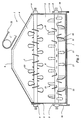
- Figure 2 is a longitudinal sectional view of the device shown in Figure 1, seen in the direction according to the arrow II.
- Figure 3 shows a part of a front view of the device shown in Figures 1 and 2.
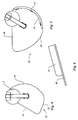
- Figure 4 is a side view of a blade secured to the upper shaft of the device.
- Figure 5 is a side view of a blade secured to the lower shaft of the device.
- Figure 6 is a side view of Figure 5.
- the metering device illustrated in the Figures comprises a hopper 1, which is provided with a sloping rear wall 2, which joins a vertically extending front wall 4 via a trough-shaped bottom 3.
- the rear wall 2 and the front wall 4 are interconnected along part of their height by side walls 5 extending upwards from the trough-shaped bottom 3, whilst the diameter of the upper part of the hopper 1 gradually becomes smaller towards an inlet opening 6 provided at the upper side of the hopper.
- Two horizontally disposed shafts 7 and 8, one being located above the other, are provided inside the hopper, said shafts being supported so as to be rotatable about their axes in journals 9 mounted on the side walls 5.
- the upper shaft 7 is thereby slightly shifted with respect to the vertical plane through the axis of rotation of the lower shaft 8, in the direction of the sloping rear wall 2 of the hopper.
- the shafts in the illustrated embodiment may be driven via belt or chain transmissions 10 and 11, from a motor 12 mounted at the front side of the hopper, which motor 12 may for example be an electromotor or a hydromotor.
- the shafts 7 and 8 may be rotated in the direction of the arrows A and B respectively; thus the two shafts rotate in the same direction during operation.
- a plurality of blades 13 are secured to the shaft 7, said blades preferably being shaped as illustrated in Figure 4.
- the leading edge 14 of the blade 13 is curved, and the outer edge 15 of the blade extends more or less concentrically about the central axis of the shaft 7, whilst the trailing edge 16 is substantially rectilinear.
- the plate-shaped blades 13 are secured to the shaft 7 in such a manner, that they include an angle with a plane extending perpendicularly to the shaft 7.
- the blades 13 mounted on the right-hand part of the shaft 7 are thereby disposed in an oblique direction opposed to the direction of the blades mounted on the left-hand part of the shaft 7.
- a few elongated plate-shaped ejection blades 17 are mounted on the central part of the further shaft 8 and near the ends of said shaft 8, said ejection blades 17 extending at least substantially tangentially with respect to the outer circumference of the shaft 8 in question, as will be apparent in particular from Figure 1.
- blades 18, which are shown in more detail in Figures 5 and 6, are provided on the outer parts of the shaft 8.
- Said blades 18 have an outer edge 19 which extends concentrically about the central axis of the shaft, said outer edge blending into a curved edge 19' at the front side of the blade, seen in the intended direction of rotation according to the arrow B.
- the blade is bounded by a boundary edge 20, which extends radially with respect to the central axis of the shaft.
- a strip-shaped part 21 extending perpendicularly to the blade 18 is secured to the leading edge 19 of the blade 18.
- the lower shaft 8 is located near a horizontally extending ejection slot 22, which is provided near the transition between the trough-shaped bottom 3 and the vertically extending front wall 4.
- the upper boundary edge 23 of the ejection slot 22 is thereby located some distance above the horizontal plane including the central axis of the shaft 8.
- the lower boundary edge 24 of the ejection slot lies in the part of the trough-shaped bottom 3 that extends upwards from the lowermost point of the trough-shaped bottom, in the direction of the front wall 4.
- a closing plate 25 which extends concentrically with respect to the trough-shaped bottom 3, is disposed under the trough-shaped bottom, said closing plate being pivotable about the journals 9 of the lower shaft 8 by means of side plates 26.
- the closing plate 25 is pivotable by means of a lever 27 secured to the closing plate.
- the closing plate 25 may be locked in a desired position by means of a set bolt 28.
- plate-shaped regulating valves 29 are provided near the upper side of the ejection slot 22, on either side of the plane of symmetry of the device extending perpendicularly to the shafts 7 and 8.
- Two slotted holes 30 are provided in each of said regulating valves 29, through which slotted holes bolts extend, on which clamping nuts 31 are screwed. It will be apparent that said regulating valves are vertically adjustable, the construction of the slotted holes 30 being such that the lower edge of each regulating valve is also slightly adjustable at an angle with respect to the horizontal.
- casing soil to be handled with the device may for example be supplied to the hopper 1 by means of a conveyor belt 32, through the inlet opening provided near the upper side of the metering device, and that near the upper end of the sloping wall 2.
- the upper shaft 7 rotating in the direction according to the arrow A during operation will thereby take care of it that the material is distributed in the best possible manner over the entire width of the upper part of the hopper 9 between the vertically extending walls 5. Furthermore this upper shaft 7, which is provided with blades, prevents the formation of bridges in the upper part of the hopper.
- the casing soil will be ejected through the ejection slot 22 by means of the ejection blades 17 secured to the lower shaft and the strip-shaped parts 21 secured to the blades 18, which function as ejection blades.
- the blades 18, which are disposed with opposite pitch on both sides of the plane of symmetry of the device extending perpendicularly to the shafts 7 and 8, will thereby effect a certain displacement of the casing soil towards the outside of the hopper, in order to ensure that the casing soil is distributed as evenly as possible over the entire width of the hopper.
- the casing soil may be thrown directly onto for example a compost-containing bed for raising mushrooms or the like, which is passed under the device during operation, or onto a conveyor belt, by means of which the casing soil is supplied, in a manner known per se, to a compost-containing bed for raising mushrooms or the like located inside a growing room.
- the correct layer thickness may thereby be obtained by adjusting the adjustable bottom part and the plate-shaped regulating valves 29.
- the device may furthermore be provided with a drivable roller 33 or roughening shaft for influencing the structure of the covering layer and/or with drivable discs 34 for trimming the sides of the layer applied.
- the device according to the invention is particularly suitable for being placed on a covering unit of a lorry or on existing filling machines for impregnated compost, whereby compost is directly provided in the beds with a layer of casing soil during filling.
Landscapes
- Life Sciences & Earth Sciences (AREA)
- Mycology (AREA)
- Environmental Sciences (AREA)
- Filling Or Emptying Of Bunkers, Hoppers, And Tanks (AREA)
Applications Claiming Priority (2)
| Application Number | Priority Date | Filing Date | Title |
|---|---|---|---|
| NL9301490 | 1993-08-31 | ||
| NL9301490A NL9301490A (nl) | 1993-08-31 | 1993-08-31 | Doseerinrichting voor het aanbrengen van dekaarde op compost voor het opkweken van champignons of dergelijke. |
Publications (1)
| Publication Number | Publication Date |
|---|---|
| EP0640278A1 true EP0640278A1 (fr) | 1995-03-01 |
Family
ID=19862808
Family Applications (1)
| Application Number | Title | Priority Date | Filing Date |
|---|---|---|---|
| EP19940202228 Withdrawn EP0640278A1 (fr) | 1993-08-31 | 1994-08-02 | Dispositif de dosage pour appliquer une couche de sol de recouvrement sur du compost pour cultiver des champignons ou analogues |
Country Status (3)
| Country | Link |
|---|---|
| EP (1) | EP0640278A1 (fr) |
| NL (1) | NL9301490A (fr) |
| PL (1) | PL304836A1 (fr) |
Cited By (1)
| Publication number | Priority date | Publication date | Assignee | Title |
|---|---|---|---|---|
| CN112056148A (zh) * | 2020-08-31 | 2020-12-11 | 庆元县菇星节能机械有限公司 | 一种菌棒装袋机 |
Families Citing this family (1)
| Publication number | Priority date | Publication date | Assignee | Title |
|---|---|---|---|---|
| CN102603380A (zh) * | 2012-03-05 | 2012-07-25 | 厦门联南强生物环保科技有限公司 | 有机肥高效发酵方法及其装置 |
Citations (4)
| Publication number | Priority date | Publication date | Assignee | Title |
|---|---|---|---|---|
| FR2265256A1 (en) * | 1974-03-26 | 1975-10-24 | Juscafresa Jaime | Fertiliser spreading attachment for trailer - has drive shaft oscillated transversely by ratchet mechanism |
| US4340182A (en) * | 1980-03-19 | 1982-07-20 | Kansas State University Research Foundation | Manure spreading apparatus |
| US4371305A (en) * | 1978-02-21 | 1983-02-01 | Pannell Robert T | Material handling apparatus |
| EP0170732A2 (fr) * | 1984-01-21 | 1986-02-12 | De Dissel Beheer B.V. | Dispositif de déchargement et de dosage pour fourrage compacté, par exemple de l'herbe et produits similaires |
-
1993
- 1993-08-31 NL NL9301490A patent/NL9301490A/nl not_active Application Discontinuation
-
1994
- 1994-08-02 EP EP19940202228 patent/EP0640278A1/fr not_active Withdrawn
- 1994-08-30 PL PL30483694A patent/PL304836A1/xx unknown
Patent Citations (4)
| Publication number | Priority date | Publication date | Assignee | Title |
|---|---|---|---|---|
| FR2265256A1 (en) * | 1974-03-26 | 1975-10-24 | Juscafresa Jaime | Fertiliser spreading attachment for trailer - has drive shaft oscillated transversely by ratchet mechanism |
| US4371305A (en) * | 1978-02-21 | 1983-02-01 | Pannell Robert T | Material handling apparatus |
| US4340182A (en) * | 1980-03-19 | 1982-07-20 | Kansas State University Research Foundation | Manure spreading apparatus |
| EP0170732A2 (fr) * | 1984-01-21 | 1986-02-12 | De Dissel Beheer B.V. | Dispositif de déchargement et de dosage pour fourrage compacté, par exemple de l'herbe et produits similaires |
Cited By (1)
| Publication number | Priority date | Publication date | Assignee | Title |
|---|---|---|---|---|
| CN112056148A (zh) * | 2020-08-31 | 2020-12-11 | 庆元县菇星节能机械有限公司 | 一种菌棒装袋机 |
Also Published As
| Publication number | Publication date |
|---|---|
| NL9301490A (nl) | 1995-03-16 |
| PL304836A1 (en) | 1995-03-06 |
Similar Documents
| Publication | Publication Date | Title |
|---|---|---|
| DE2000553C3 (fr) | ||
| EP1163834B1 (fr) | Dispositif à répartir pour hacheur | |
| EP1514466B1 (fr) | Dispositif de coupe et de distribution | |
| US6007272A (en) | Asphalt paver with remixing conveyor system | |
| US6209808B1 (en) | Spreader attachment | |
| JPH03240408A (ja) | 作物処理装置 | |
| EP0104622B1 (fr) | Dispositif d'épandage de fumier, d'engrais et autres | |
| EP0212337B2 (fr) | Dispositif pour moissonneuse-batteuse pour la distribution de balle | |
| US4273495A (en) | Apparatus and method for laying compost in a mushroom bed | |
| FI95109C (fi) | Rumpuhakkurilaitteisto | |
| GB2163032A (en) | A spreader | |
| EP0121751A1 (fr) | Machine combinée pour le traitement de balles de foin ou de paille | |
| CA2026682A1 (fr) | Methode et appareil pour le paillage a l'aide d'herbe, de feuilles ou de materiaux semblables | |
| DE1592657B2 (de) | Kompostumsetzmaschine | |
| EP0640278A1 (fr) | Dispositif de dosage pour appliquer une couche de sol de recouvrement sur du compost pour cultiver des champignons ou analogues | |
| EP0670107A1 (fr) | Appareil et méthode pour doser de l'ensilage | |
| DE3546679C1 (en) | Combine harvester chaff distributing attachment | |
| DE2902484A1 (de) | Fuell- und entnahmevorrichtung fuer runde silos | |
| DE69121086T2 (de) | Steinauffangvorrichtung für Mähdrescher | |
| US6817286B2 (en) | Mushroom compost compacting assembly | |
| GB2173682A (en) | Spreading machines | |
| EP0615967A1 (fr) | Machine pour aérer les tas de compost | |
| EP0237645A2 (fr) | Distributeur | |
| EP0838142B1 (fr) | Outil pour épandre de la matière | |
| AT506767A1 (de) | Befülleinrichtung für feste brennstoffe |
Legal Events
| Date | Code | Title | Description |
|---|---|---|---|
| PUAI | Public reference made under article 153(3) epc to a published international application that has entered the european phase |
Free format text: ORIGINAL CODE: 0009012 |
|
| AK | Designated contracting states |
Kind code of ref document: A1 Designated state(s): AT BE DE DK FR GB IE IT LU NL |
|
| 17P | Request for examination filed |
Effective date: 19950821 |
|
| 17Q | First examination report despatched |
Effective date: 19951005 |
|
| STAA | Information on the status of an ep patent application or granted ep patent |
Free format text: STATUS: THE APPLICATION IS DEEMED TO BE WITHDRAWN |
|
| 18D | Application deemed to be withdrawn |
Effective date: 19960416 |