EP0640415B1 - Vorrichtung zum Beheben von Schäden an Autokarosserieteilen - Google Patents
Vorrichtung zum Beheben von Schäden an Autokarosserieteilen Download PDFInfo
- Publication number
- EP0640415B1 EP0640415B1 EP94113097A EP94113097A EP0640415B1 EP 0640415 B1 EP0640415 B1 EP 0640415B1 EP 94113097 A EP94113097 A EP 94113097A EP 94113097 A EP94113097 A EP 94113097A EP 0640415 B1 EP0640415 B1 EP 0640415B1
- Authority
- EP
- European Patent Office
- Prior art keywords
- pulling
- component
- retaining element
- welding
- pulling device
- Prior art date
- Legal status (The legal status is an assumption and is not a legal conclusion. Google has not performed a legal analysis and makes no representation as to the accuracy of the status listed.)
- Expired - Lifetime
Links
- 238000003466 welding Methods 0.000 claims description 29
- 238000001816 cooling Methods 0.000 claims description 20
- 239000002826 coolant Substances 0.000 claims description 4
- 238000010438 heat treatment Methods 0.000 claims description 3
- 238000003754 machining Methods 0.000 claims description 2
- 238000007493 shaping process Methods 0.000 claims 3
- 238000007789 sealing Methods 0.000 description 20
- 230000006835 compression Effects 0.000 description 12
- 238000007906 compression Methods 0.000 description 12
- 238000000034 method Methods 0.000 description 11
- 230000008569 process Effects 0.000 description 11
- 239000012530 fluid Substances 0.000 description 5
- 230000009471 action Effects 0.000 description 4
- 238000003825 pressing Methods 0.000 description 3
- 230000008439 repair process Effects 0.000 description 3
- 230000000712 assembly Effects 0.000 description 2
- 238000000429 assembly Methods 0.000 description 2
- 239000000463 material Substances 0.000 description 2
- 239000012528 membrane Substances 0.000 description 2
- 239000002184 metal Substances 0.000 description 2
- 238000011084 recovery Methods 0.000 description 2
- 238000010008 shearing Methods 0.000 description 2
- 230000037237 body shape Effects 0.000 description 1
- 238000010276 construction Methods 0.000 description 1
- 230000003292 diminished effect Effects 0.000 description 1
- 238000006073 displacement reaction Methods 0.000 description 1
- 238000005516 engineering process Methods 0.000 description 1
- 230000006872 improvement Effects 0.000 description 1
- 230000007246 mechanism Effects 0.000 description 1
- 239000003973 paint Substances 0.000 description 1
- 238000010422 painting Methods 0.000 description 1
- 238000010791 quenching Methods 0.000 description 1
- 230000000171 quenching effect Effects 0.000 description 1
- 230000011514 reflex Effects 0.000 description 1
- 239000004575 stone Substances 0.000 description 1
- 210000004243 sweat Anatomy 0.000 description 1
Images


Classifications
-
- B—PERFORMING OPERATIONS; TRANSPORTING
- B21—MECHANICAL METAL-WORKING WITHOUT ESSENTIALLY REMOVING MATERIAL; PUNCHING METAL
- B21D—WORKING OR PROCESSING OF SHEET METAL OR METAL TUBES, RODS OR PROFILES WITHOUT ESSENTIALLY REMOVING MATERIAL; PUNCHING METAL
- B21D1/00—Straightening, restoring form or removing local distortions of sheet metal or specific articles made therefrom; Stretching sheet metal combined with rolling
- B21D1/06—Removing local distortions
-
- B—PERFORMING OPERATIONS; TRANSPORTING
- B23—MACHINE TOOLS; METAL-WORKING NOT OTHERWISE PROVIDED FOR
- B23P—METAL-WORKING NOT OTHERWISE PROVIDED FOR; COMBINED OPERATIONS; UNIVERSAL MACHINE TOOLS
- B23P6/00—Restoring or reconditioning objects
-
- Y—GENERAL TAGGING OF NEW TECHNOLOGICAL DEVELOPMENTS; GENERAL TAGGING OF CROSS-SECTIONAL TECHNOLOGIES SPANNING OVER SEVERAL SECTIONS OF THE IPC; TECHNICAL SUBJECTS COVERED BY FORMER USPC CROSS-REFERENCE ART COLLECTIONS [XRACs] AND DIGESTS
- Y10—TECHNICAL SUBJECTS COVERED BY FORMER USPC
- Y10S—TECHNICAL SUBJECTS COVERED BY FORMER USPC CROSS-REFERENCE ART COLLECTIONS [XRACs] AND DIGESTS
- Y10S72/00—Metal deforming
- Y10S72/705—Vehicle body or frame straightener
Definitions
- the invention relates generally to a device for deformation of thin-walled components and in particular a device for Repair damage to car body parts with one on deforming component weldable holding member and a pulling device for applying tensile forces to the holding member.
- the generic FR-A-2550971 discloses an apparatus of the type mentioned at the beginning.
- the invention has for its object in a Device of the type mentioned in the preamble of claim 1 to improve the work result and their To make usability more universal.
- a defined end position of the pulling device can be the zero level of the original body shape or a defined over-stretching can be set.
- damaged areas can correspond to the rounding longer distance and therefore larger draws according to the bill be worn.
- Reaches the drawbar with the adjustable Depth stop a defined end position can be adjusted accordingly holding members of different sizes can be used.
- any essential welding parts can be used as holding members, can either be specially adapted to the damage or inexpensive common metallic washers can be used.
- a device for supplying coolant, in particular of air, to the heated, reshaped area can be through the defined cooling in the manner of "quenching" it accompanying strength improvement positive for the stability of the use the deformed area.
- quenching it accompanying strength improvement positive for the stability of the use the deformed area.
- they occur at the state of the Technology entered mechanical stresses, which may be a require thermal aftertreatment in the case of the invention Device only to a lesser extent or not at all.
- the Cooling air in a simple manner using the used Compressed air source are supplied. This will make the work again much faster, immediately after pulling the whole recovered area cooled and it can be immediately next to the processed place can be continued with the further treatment. This makes the device according to the invention even more suitable, too repair larger damage.
- a motorized device to loosen the welded Holding member accelerates the work process again without the operator additional burden.
- the manually operable is advantageously Control element an operating lever or pusher successive, assigned to the individual functional sequences Has actuation positions. Through this the individual Operating positions assigned to functional sequences can be operated by the operator full manual control over all in a simple manner Keep functional processes.
- a defined, preprogrammable pull and time Cooling behavior which always ensures the optimal process, can alternatively can be achieved with an electrical and / or pneumatic Control device that has an automated sequence of functional sequences Welding on, pulling, cooling, turning off and / or returning to the Starting position causes.
- the holding member is pulled smoothly after welding, preferably by a in the pneumatic supply line to the pneumatically operated throttle arranged throttle Force peaks due to soft start of the drawing process are avoided the unwanted detachment of the holding member excluded. That initially gentle pulling carries the hottest state of the material to be deformed Bill and avoids unwanted overstretching in the area of Welding point.
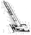
- the device designated as 1 for deforming thin-walled components includes a head part 2 and one on this Handle part 3 fastened vertically approximately in the middle thereof.
- a motor actuatable pulling device 4 Within the head part 2 is essentially a motor actuatable pulling device 4, a motor-operated device 5 to release the holding member 7 and a stop 6 for the pulling device 4 arranged.
- a pneumatic Control assembly 9 In or on the handle part 2 are essentially one manually operable control element 8, a pneumatic Control assembly 9, a device 14 for the automatic feeding of coolant and / or automatically causing the detachment of the Holding member 7 and an electrical switching device 10 arranged.
- electrical Feed device 11 In the handle part 3 and arranged in the head part 2 are electrical Feed device 11 in the form of a feed line 48 for the electrical Welding the holding member 7 to the component 12 to be deformed.
- a foot part 26 is frictionally engaged held, screwed on, by the locking force of a locking element and / or exchangeably attached by a bayonet.
- the contact surface 51 of the foot part 26, with which the device 1 compared to the Supporting component 12 has an opening depending on the application round, elongated, oval or polygonal shape and can according to the damage to be processed by exchanging the foot section 26 can be optimally adjusted.
- the overall substantially cylindrical head part 2 instructs at its upper end a dial 15 for the depth stop 6, the has approximately the same diameter as the head part 2.
- the dial 15 is with a threaded bolt or an adjusting screw 16 Fine thread connected in a thread 17 of the head part 2 is rotatable and thus axially adjustable.
- a piston 18 is axially displaceable in a cylinder chamber 19 held.
- a rotatable bearing 20 is located in the central region of the piston 18 arranged, on the inner bearing shell a tie rod 21 so is appropriate that this is rotatable relative to the piston 18, however is not kept axially displaceable.
- a membrane 22 on the outside with the Housing of the head part 2 and in the middle connected to the piston 18 so that this the cylindrical space 23 upwards movable and sealing completes.
- a plate-shaped support disk 53 held on the pull rod 21.
- the cylindrical space 23 surrounds the Drawbar 21 and is fluid-tight against this.
- a pneumatic feed line 24 connects the cylindrical space 23 with the pneumatic control assembly 9 so that the piston 18th counter to the force of the face on which it is supported Compression spring 25 when a fluid is supplied through the supply line 24 motor-driven is moved into the upper axial end position.
- the upper end of the pull rod 21 lies against the depth stop 6.
- the pressurized fluid from the space 23 can pass through the environment Lead 24 either after opening the more detailed at a later location described valve 52 or without this valve permanently in less Quantity can be discharged along the feed line 43 and it comes to pass the piston 18 and the attached tie rod 21 in the lower axial end position, the original starting position.
- This lower axial end position is chosen so that the pull rod 21 with the holding member 7 attached to it, the foot part of the device 26 towered far ahead.
- the length of the protrusion can be selected by the Diameter or the size of the holding member 7 are influenced, however, is preferably at least about 3 mm, 5 mm, 8 mm or more; so that usual depths of damage in any case from the Device 1 according to the invention can be detected.
- a plate 27 attached, which is an eccentric rotatable and tiltable Bearing for holding a connecting rod 28.
- the connecting rod 28 is on its front end rotatable and tiltable off-center with the plate 27 and at its rear end rotatable and tiltable with one Push / pull rod 29 of the pneumatic piston 30 connected.
- the Pneumatic piston 30 is in the pneumatic cylinder 31 by the force of Compression spring 32 without supplying a pressurized fluid along the lead 33 held in its right axial end position.
- the compression spring 32 shown only schematically in the figures is preferred a fatigue-free spiral spring, the forces of which are so dimensioned that counter to mechanical friction, the right axial end position of the piston 30 is always reached when there is ambient pressure in the cylinder 31, whereas the plate 27 and the pull rod 21 are rotated when over the supply line 33 is supplied with fluid under pressure.
- the plate 27 and the pull rod 21 are rotated when over the supply line 33 is supplied with fluid under pressure.
- the feed line 33 is for automatically causing shearing a multi-function valve 34 which also acts as a pressure relief valve connected, which is also shown enlarged in Fig. 2.
- the Multi-function valve 34 connects the feed line 33 to the pneumatic one Control module 9 and, as described in more detail later, temporarily at its entrance with the supply line 24 to the cylindrical space 23 communicate.
- a device 5 for automatic Loosening the holding member 7 formed.
- valve body 35 emerges from its sealing system the upper stop shown in Fig. 2 against the force of Compression spring 36 back, releases the feed line 33 and closes with its lower conical end, the opening 54 is fluid-tight, so that the thereupon the pressure in cylinder 31 increases to the above described rotation of the plate 27 and the pull rod 21 leads.
- the control element 8 pivoted back into the position S2 + 3, seals it Sealing element 44 fluidly seals the chamber 42 against the valve 34. It then occurs the sealing element 35 by the action of the compression spring 36 its upper stop back, with the lower opening 54 released through which the cylinder 31 is subsequently vented.
- Under The action of the compression spring 32 takes the piston 30 and thus the Device 5 for releasing the holding member their original Starting position.
- a rod-shaped pneumatic control member 37 axially displaceable held.
- the shorter lever arm 50 of the pivotable manual control element 8 which is the four operating positions designated S0 to S4 in the figures having.
- a conical sealing element 38 is connected to it in a sealing manner.
- the right end of the sealing element 38 in the figures engages a schematically illustrated compression spring 41 arranged in the chamber 39 on.
- the sealing element 38 can be in the actuation positions S2 + 3 and S4 air supplied from the pneumatic supply 40 from the chamber 39 are passed into the chamber 42.
- the pneumatic feeder 40 is during operation in a known manner with any suitable Compressed air source connected.
- the Lead 43 extends from the chamber 42 to the foot part 26 and through the foot part 26, from which the cooling air towards machining and heated by welding workpiece 12 out becomes.
- FIG. 2 and FIG. 3 In a further embodiment is in the feed line 43 another, enlarged in FIG. 2 and FIG. 3 only schematically Pressure relief valve 52 shown arranged, which a supply of Cooling air only after reaching the upper end position of the pull rod 21 and effected before the excess pressure for detaching the holding member 7.
- the pressure relief valve 52 includes a ball 55, which is by the compression spring 56 sealing in its upper position at an opening to chamber 42 is held.
- the opening pressure can be adjusted by means of the adjusting screw 57 of the pressure relief valve 52 fine-tuned so that the feed 43rd only from the desired overpressure, which is, for example, 6 bar can communicate with the chamber 42.
- a conical sealing element 44 Under the action of the schematically illustrated compression spring 45 the left end face held in a sealing stop.
- the Sealing element 44 is on the right, radially tapered part of the rod-shaped pneumatic control member 37 so longitudinally attached that when pressing the control element 8 in the position S2 + 3 the conical sealing element 38 is no longer on the end face is present, but still no opening of the sealing element 44 against the force the compression spring 45 is done. If you press the Operating element 8 in position S4, the sealing element 44 by the radially expanded area of the control element 37 is detected on the end face and moved to the right so that access to the multi-function valve 34 is released.
- the different successive, the individual Operating positions assigned to operational sequences are S0 to S4 tactile for the operator simply by one step at a time to detect increasing force increase.
- the position S1 of the control element 8 is shown in FIG. 4 shown advanced position of the pull rod 21 is taken. At Touching the mass associated with the sweat potential deforming component 12 with the holding member 7 flows over with the Drawbar 21 conductively connected electrical lead 48 Welding current, the current welding of the holding member 7 on Component 12 causes.
- the pull rod 21 within the head part 2 is electrical kept isolated or the entire device 1 from one surrounding the insulating casing.
- the supply of the welding current from the flexible supply line 48 to the pull rod 21 can by an elastic Cable routing or as described above by a firm attached rotatable plate.
- the supply device 47 can be any one commercial device suitable for electrical welding, such as for example a welding transformer with the corresponding electrical control.
- this includes Supply device 47, however, an adjustable electrical Control device that is adjustable in the component 12 to a defined Heat input with predeterminable time behavior that leads to a defined Heating during and / or after welding the holding member 7 causes.
- the feed line 43 to the foot part 26 and the feed line 24 to cylindrical space 23 are in the first Embodiment designed without the additional pressure relief valve 52 so that initially during the displacement of the piston 18 and the tie rod 21 only in a small amount of cooling air and due to the pressure increase at A significantly increased amount of cooling air is reached when the end position is reached is supplied, see FIG. 6.
- Position S4 shown is the connection to the multi-function valve 34 against the tactile perceptible additional force of the compression spring 45 released and there is the described pressure increase, which leads to a Unscrewing the holding member 7 from the component 12 leads.
- the feeds 23, 33 and 43 can be dimensioned so that also an unskilled operator who immediately controls 8 after Welding fully pushed through to position S4, an optimal one Recovery result received.
- the respective supply lines are for this purpose 24, 33, 43 designed or equipped with nozzles or throttles that the slowly increasing pressure initially turns into a gentle one Stepping back of the pull rod 21 leads, then the cooling air supply sets and then the shearing of the holding member 7 takes place. It
- the pneumatic control device 9 thus results in a Automation that processes the welding, pulling, Cooling, turning off and / or returning to the starting position with optimized time behavior.
- the feed line 49 can be control lines for the actuators included and the supply device 47 the corresponding electrical and electronic control assemblies.
- control element 8 When the control element 8 is released, it enters the position S0 and enter the sealing elements 38 and 44 in the sealing Starting position back.
- the air escapes from the cylindrical space 23 along the supply line 24 into the chamber 42, from where it through the Lead 43 is guided to the foot part 26 and exits there. Consequently is the device 1 in its initial state and is for further processing operations can be used.
Landscapes
- Engineering & Computer Science (AREA)
- Mechanical Engineering (AREA)
- Straightening Metal Sheet-Like Bodies (AREA)
- Vehicle Cleaning, Maintenance, Repair, Refitting, And Outriggers (AREA)
- Lining Or Joining Of Plastics Or The Like (AREA)
- Automobile Manufacture Line, Endless Track Vehicle, Trailer (AREA)
Description
Es zeigen:
- Fig. 1
- eine perspektivische Ansicht einer im Querschnitt in Längsrichtung dargestellten erfindungsgemäßen Vorrichtung schräg von vorn,
- Fig. 2
- die in Fig. 1 dargestellte Vorrichtung in einer Aufsicht von der Seite auf den Querschnitt in Längsrichtung,
- Fig. 3
- eine schematische Darstellung grundlegender Funktionsbaugruppen der in den Fig. 1 und 2 dargestellten Vorrichtung,
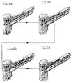
- Fig. 4
- den Vorgang des Anschweißens des Haltegliedes bei einer im Querschnitt in Längsrichtung dargestellten Vorrichtung,
- Fig. 5
- den Vorgang des Ziehens und die damit einhergehende Rückverformung des bearbeiteten Bauteils,
- Fig. 6
- das Zuführen von Kühlluft zum Abkühlen des rückverformten Bauteils,
- Fig. 7
- den Vorgang des Ablösens des Haltegliedes vom rückverformten Bauteil durch dessen Abdrehen,
- Fig. 8a bis d
- die Funktionsabläufe der Fig. 4 bis 7 in ihrer Abfolge in perspektivischer Darstellung.
Claims (13)
- Vorrichtung (1) zum Verformen von dünnwandigen Bauteilen (12), zum Beheben von Schäden an Autokarosserieteilen (12), mit einem an dem zu verformenden Bauteil (12) anschweißbaren, an einem Ende einer Zugstange (21) angeordneten Halteglied (7), und einer Zugvorrichtung (4) zum Aufbringen von Zugkräften auf das Halteglied (7), wobei die Zugvorrichtung (4) motorisch betätigbar ist und ein zu verformender Teil des Bauteils (12) nach dem Anschweißen des Haltegliedes (7) durch die Zugvorrichtung (4) motorisch betätigt in eine vorgebbare Endstellung bringbar ist,
gekennzeichnet durch einen am anderen Ende der Zugstange (21) angeordneten einstellbaren Tiefenanschlag (6), mit welchem das Nullniveau der ursprünglichen Karosserieteile oder auch ein definiertes Überstrecken, mit welchem der Ziehtiefe des Schadens entsprechend Rechnung getragen werden kann, für jeden Vorgang einstellbar ist, zum Erreichen einer definierten Endstellung der Zugvorrichtung (4). - Vorrichtung nach Anspruch 1,
gekennzeichnet durch eine Einrichtung (13) zum Zuführen von Kühlmittel, insbesondere von Luft, zu dem erwärmten rückverformten Teil des Bauteils (12). - Vorrichtung nach Anspruch 1 oder 2,
gekennzeichnet durch eine motorische betätigte Einrichtung (5) zum Lösen des angeschweißten Haltegliedes (7). - Vorrichtung nach einem der vorstehenden Ansprüche,
gekennzeichnet durch ein einziges, manuell betätigbares Bedienungselement (8) für die Funktionsabläufe Anschweißen, Ziehen, Kühlen, Abdrehen und/oder Rückkehr in die Anfangsposition. - Vorrichtung nach Anspruch 4,
dadurch gekennzeichnet, daß das manuell betätigbare Bedienungselement (8) den einzelnen Funtkionsabläufen zugeordnete Betätigungsstellungen (SO, S1, S2+3, S4) umfasst. - Vorrichtung nach einem der vorstehenden Ansprüche, insbesondere nach den Ansprüchen 4 oder 5,
gekennzeichnet durch eine in einem Griffteil (2) der Vorrichtung (1) angeordnete pneumatische Steuerungsbaugruppe (9), welche pneumatische Steuerungsvorgänge durch die axiale Stellung eines einzigen pneumatischen Steuerungsorgans (37) bewirkt. - Vorrichtung nach einem der vorstehenden Ansprüche,
gekennzeichnet durch eine Einrichtung (14), die bei Erreichen der Endstellung der Zugvorrichtung (4) die Zufuhr von Kühlluft und/oder das Lösen des Haltegliedes (7) vom Bauteil (12) bewirkt. - Vorrichtung nach Anspruch 7,
dadurch gekennzeichnet, daß die Einrichtung (14) zumindest ein Überdruckventil (34, 52) aufweist, das bei ansteigendem Druck in der Endstellung der Zugvorrichtung (4) öffnet und den Austritt von Kühlluft und/oder das Lösen des Haltegliedes vom Bauteil (12) bewirkt. - Vorrichtung nach einem der vorstehenden Ansprüche,
dadurch gekennzeichnet, daß das Ziehen des Haltegliedes (7) nach dem Anschweißen ruckfrei erfolgt, wofür insbesondere eine Drossel in einer pneumatischen Zuleitung (24) zu der Zugvorrichtung (4) angeordnet ist. - Vorrichtung nach einem der vorstehenden Ansprüche,
dadurch gekennzeichnet, daß eine elektrische und/oder pneumatische Steuereinrichtung (9) einen automatisierten Ablauf der Funktionsabläufe Anschweißen, Ziehen, Kühlen, Abddrehen und/oder Rückkehr in die Anfangsposition bewirkt. - Vorrichtung nach einem der vorstehenden Ansprüche,
dadurch gekennzeichnet, daß die Zugvorrichtung (4) sich beim Ziehen mit einem oder mehreren einsetzbaren Fußteilen (26) mit auswählbarer Auflageform gegen das Bauteil (12) abstützt. - System zur Bearbeitung von dünnwandigen Bauteilen,
insbesondere zum Beheben von Schäden an Autokarosserien (12), umfassend eine Vorrichtung nach einem der Ansprüche 1 bis 11 sowie ein Versorgungsgerät (47) für das elektrische Schweißen des Haltegliedes (7) an das Bauteil (12). - System nach Anspruch 12,
dadurch gekennzeichnet, daß das Versorgungsgerät (47) einen einstellbaren Wärmeeintrag mit vorgebbarem Zeitverhalten bewirkt, der zu einer einstellbaren Erwärmung während und/oder nach dem Anschweißen des Haltegliedes (7) führt.
Applications Claiming Priority (2)
| Application Number | Priority Date | Filing Date | Title |
|---|---|---|---|
| DE9312980 | 1993-08-30 | ||
| DE9312980U | 1993-08-30 |
Publications (2)
| Publication Number | Publication Date |
|---|---|
| EP0640415A1 EP0640415A1 (de) | 1995-03-01 |
| EP0640415B1 true EP0640415B1 (de) | 1999-02-03 |
Family
ID=6897405
Family Applications (1)
| Application Number | Title | Priority Date | Filing Date |
|---|---|---|---|
| EP94113097A Expired - Lifetime EP0640415B1 (de) | 1993-08-30 | 1994-08-23 | Vorrichtung zum Beheben von Schäden an Autokarosserieteilen |
Country Status (7)
| Country | Link |
|---|---|
| US (1) | US5546786A (de) |
| EP (1) | EP0640415B1 (de) |
| JP (1) | JP3604038B2 (de) |
| KR (1) | KR100317507B1 (de) |
| AT (1) | ATE176413T1 (de) |
| DE (1) | DE59407760D1 (de) |
| ES (1) | ES2128472T3 (de) |
Families Citing this family (9)
| Publication number | Priority date | Publication date | Assignee | Title |
|---|---|---|---|---|
| FR2755047B1 (fr) * | 1996-07-02 | 1999-04-09 | Ardwell Production | Dispositif de redressement de tole par l'exterieur, notamment pour la carrosserie automobile |
| DE10026794A1 (de) * | 2000-02-23 | 2001-09-13 | Wolfgang Winkler | Verfahren sowie Vorrichtung zum Reparieren von Beschädigungen |
| DE10014235A1 (de) * | 2000-03-22 | 2001-09-27 | Adolf Wuerth Gmbh & Co Kg | Vorrichtung zum Entfernen von Beulen |
| US6539770B2 (en) * | 2001-05-22 | 2003-04-01 | Goran K. Olsson | Dent pulling apparatus and system |
| US20230072718A1 (en) * | 2011-04-28 | 2023-03-09 | Allstate Insurance Company | Automatic damage detection and repair assessment |
| US20160158819A1 (en) * | 2014-12-03 | 2016-06-09 | Paul E. Johnson | Compact Pneumatic Auto Body Hammer with Fine Control of Impact Force |
| EP3028821A1 (de) * | 2014-12-03 | 2016-06-08 | HILTI Aktiengesellschaft | Steuerungsverfahren für eine Handwerkzeugmaschine |
| CN110369556B (zh) * | 2019-08-29 | 2020-12-18 | 王绪根 | 一种汽车凹陷修复仪及汽车凹陷修复方法 |
| CN112874490A (zh) * | 2021-01-22 | 2021-06-01 | 天津鸿蒙智造科技有限公司 | 一种汽车外观件数据复原无腻子修复方法 |
Citations (1)
| Publication number | Priority date | Publication date | Assignee | Title |
|---|---|---|---|---|
| EP0544191A1 (de) * | 1991-11-24 | 1993-06-02 | Kosei Ishihara | Blechziehvorrichtung |
Family Cites Families (7)
| Publication number | Priority date | Publication date | Assignee | Title |
|---|---|---|---|---|
| DE1162315B (de) * | 1960-11-14 | 1964-02-06 | Linke Hofmann Busch | Vorrichtung zum Geraderichten von eingespannten Blechen |
| US3801772A (en) * | 1973-08-27 | 1974-04-02 | Gen Motors Corp | In-ding repair tool |
| DE2515296C3 (de) * | 1975-04-08 | 1980-04-17 | Ets. Robert Brendle Et Cie. S.A., Saint-Louis (Frankreich) | Ausbeulgerät |
| US4376385A (en) * | 1980-09-24 | 1983-03-15 | Davis Michael G | Slide hammer having spot weldable surface engaging capability |
| FR2550971A1 (fr) * | 1983-08-30 | 1985-03-01 | Trinome Sarl | Appareil a redresser les toles |
| IT1226671B (it) * | 1988-12-22 | 1991-01-31 | Garda Impianti Srl | Apparecchiatura per la riparazione di scocche incidentate di autoveicoli |
| US5203196A (en) * | 1991-10-07 | 1993-04-20 | Jenkins Fremont T | Dent puller |
-
1994
- 1994-08-23 AT AT94113097T patent/ATE176413T1/de not_active IP Right Cessation
- 1994-08-23 ES ES94113097T patent/ES2128472T3/es not_active Expired - Lifetime
- 1994-08-23 DE DE59407760T patent/DE59407760D1/de not_active Expired - Fee Related
- 1994-08-23 EP EP94113097A patent/EP0640415B1/de not_active Expired - Lifetime
- 1994-08-30 JP JP20561894A patent/JP3604038B2/ja not_active Expired - Lifetime
- 1994-08-30 KR KR1019940021552A patent/KR100317507B1/ko not_active Expired - Fee Related
- 1994-08-30 US US08/297,970 patent/US5546786A/en not_active Expired - Fee Related
Patent Citations (1)
| Publication number | Priority date | Publication date | Assignee | Title |
|---|---|---|---|---|
| EP0544191A1 (de) * | 1991-11-24 | 1993-06-02 | Kosei Ishihara | Blechziehvorrichtung |
Also Published As
| Publication number | Publication date |
|---|---|
| US5546786A (en) | 1996-08-20 |
| KR950005442A (ko) | 1995-03-20 |
| DE59407760D1 (de) | 1999-03-18 |
| EP0640415A1 (de) | 1995-03-01 |
| JPH07148525A (ja) | 1995-06-13 |
| JP3604038B2 (ja) | 2004-12-22 |
| ES2128472T3 (es) | 1999-05-16 |
| ATE176413T1 (de) | 1999-02-15 |
| KR100317507B1 (ko) | 2002-02-19 |
Similar Documents
| Publication | Publication Date | Title |
|---|---|---|
| DE69317303T3 (de) | Selbststanzende nieten | |
| EP0079587B1 (de) | Drahtbiegemaschine | |
| CH654779A5 (de) | Pneumatisch angetriebene spannvorrichtung. | |
| EP0640415B1 (de) | Vorrichtung zum Beheben von Schäden an Autokarosserieteilen | |
| EP3242760B1 (de) | Vorrichtung und verfahren zum setzen eines verbindungselements an einem werkstück | |
| EP0620058B1 (de) | Richtmaschine für Draht | |
| DE2915327C2 (de) | Arbeitsmaschine mit Fingerschutzeinrichtung für das bewegbare Oberwerkzeug | |
| DE3235040C2 (de) | Presse zum Aufpressen von Hülsen, Kabelschuhen oder dergleichen | |
| EP1073534B1 (de) | Verfahren und vorrichtung zum warmpressen von werkstücken | |
| EP3115126B1 (de) | Bearbeitungszange | |
| EP3681655A1 (de) | Vorrichtung sowie ein verfahren zum setzen eines verbindungselements an einem werkstück | |
| DE102009000901B4 (de) | Dreistufige Ventilschaltanordnung | |
| DE10359879B4 (de) | Hydraulische Bearbeitungszange | |
| EP3650175A1 (de) | Hydraulische pumpen-ventilvorrichtung für eine pressmaschine | |
| DE4109795A1 (de) | Verfahren und einrichtung zum stanzen, biegen und/oder pressen | |
| EP0371960B1 (de) | Verfahren zum Biegen von stabförmigen Materialien | |
| DE2512492A1 (de) | Verfahren und vorrichtung zum zusammenschweissen zweier metallabschnitte, von denen jeder eine randflaeche besitzt, an ihren raendern | |
| EP1345715B1 (de) | Schmiedepresse mit stellvorrichtung auf matrizenseite | |
| EP3976319B1 (de) | Montagevorrichtung und verfahren zum montieren von bauteilen | |
| DE4241971C1 (de) | Verfahren zum Aufpressen einer Kontaktträgerhülse und hydraulische Presse zur Durchführung des Verfahrens | |
| DE2629796B2 (de) | Hydraulische Rohr- und Stabendumformmaschine | |
| DE102004007265B4 (de) | Bearbeitungszange | |
| WO2009150001A1 (de) | Montagevorrichtung für gelenke | |
| EP3575036A1 (de) | Werkzeugkopf für eine pressmaschine | |
| DE10007255A1 (de) | Einrichtung zum stempelseitigen Auswerfen von Werkstücken für Ein- oder Mehrstufenpressen |
Legal Events
| Date | Code | Title | Description |
|---|---|---|---|
| PUAI | Public reference made under article 153(3) epc to a published international application that has entered the european phase |
Free format text: ORIGINAL CODE: 0009012 |
|
| AK | Designated contracting states |
Kind code of ref document: A1 Designated state(s): AT CH DE ES FR GB IT LI NL |
|
| 17P | Request for examination filed |
Effective date: 19950318 |
|
| 17Q | First examination report despatched |
Effective date: 19950926 |
|
| GRAG | Despatch of communication of intention to grant |
Free format text: ORIGINAL CODE: EPIDOS AGRA |
|
| GRAG | Despatch of communication of intention to grant |
Free format text: ORIGINAL CODE: EPIDOS AGRA |
|
| GRAG | Despatch of communication of intention to grant |
Free format text: ORIGINAL CODE: EPIDOS AGRA |
|
| GRAH | Despatch of communication of intention to grant a patent |
Free format text: ORIGINAL CODE: EPIDOS IGRA |
|
| GRAH | Despatch of communication of intention to grant a patent |
Free format text: ORIGINAL CODE: EPIDOS IGRA |
|
| ITF | It: translation for a ep patent filed | ||
| GRAH | Despatch of communication of intention to grant a patent |
Free format text: ORIGINAL CODE: EPIDOS IGRA |
|
| GRAA | (expected) grant |
Free format text: ORIGINAL CODE: 0009210 |
|
| AK | Designated contracting states |
Kind code of ref document: B1 Designated state(s): AT CH DE ES FR GB IT LI NL |
|
| REF | Corresponds to: |
Ref document number: 176413 Country of ref document: AT Date of ref document: 19990215 Kind code of ref document: T |
|
| REG | Reference to a national code |
Ref country code: CH Ref legal event code: NV Representative=s name: BOVARD AG PATENTANWAELTE Ref country code: CH Ref legal event code: EP |
|
| GBT | Gb: translation of ep patent filed (gb section 77(6)(a)/1977) |
Effective date: 19990204 |
|
| ET | Fr: translation filed | ||
| REF | Corresponds to: |
Ref document number: 59407760 Country of ref document: DE Date of ref document: 19990318 |
|
| REG | Reference to a national code |
Ref country code: ES Ref legal event code: FG2A Ref document number: 2128472 Country of ref document: ES Kind code of ref document: T3 |
|
| PLBE | No opposition filed within time limit |
Free format text: ORIGINAL CODE: 0009261 |
|
| STAA | Information on the status of an ep patent application or granted ep patent |
Free format text: STATUS: NO OPPOSITION FILED WITHIN TIME LIMIT |
|
| 26N | No opposition filed | ||
| REG | Reference to a national code |
Ref country code: GB Ref legal event code: IF02 |
|
| PGFP | Annual fee paid to national office [announced via postgrant information from national office to epo] |
Ref country code: DE Payment date: 20070824 Year of fee payment: 14 |
|
| PGFP | Annual fee paid to national office [announced via postgrant information from national office to epo] |
Ref country code: ES Payment date: 20070828 Year of fee payment: 14 |
|
| PGFP | Annual fee paid to national office [announced via postgrant information from national office to epo] |
Ref country code: CH Payment date: 20070828 Year of fee payment: 14 Ref country code: AT Payment date: 20070827 Year of fee payment: 14 |
|
| PGFP | Annual fee paid to national office [announced via postgrant information from national office to epo] |
Ref country code: GB Payment date: 20070829 Year of fee payment: 14 |
|
| PGFP | Annual fee paid to national office [announced via postgrant information from national office to epo] |
Ref country code: NL Payment date: 20070824 Year of fee payment: 14 Ref country code: IT Payment date: 20070828 Year of fee payment: 14 |
|
| PGFP | Annual fee paid to national office [announced via postgrant information from national office to epo] |
Ref country code: FR Payment date: 20070824 Year of fee payment: 14 |
|
| REG | Reference to a national code |
Ref country code: CH Ref legal event code: PL |
|
| GBPC | Gb: european patent ceased through non-payment of renewal fee |
Effective date: 20080823 |
|
| PG25 | Lapsed in a contracting state [announced via postgrant information from national office to epo] |
Ref country code: AT Free format text: LAPSE BECAUSE OF NON-PAYMENT OF DUE FEES Effective date: 20080823 |
|
| NLV4 | Nl: lapsed or anulled due to non-payment of the annual fee |
Effective date: 20090301 |
|
| PG25 | Lapsed in a contracting state [announced via postgrant information from national office to epo] |
Ref country code: NL Free format text: LAPSE BECAUSE OF NON-PAYMENT OF DUE FEES Effective date: 20090301 |
|
| REG | Reference to a national code |
Ref country code: FR Ref legal event code: ST Effective date: 20090430 |
|
| PG25 | Lapsed in a contracting state [announced via postgrant information from national office to epo] |
Ref country code: LI Free format text: LAPSE BECAUSE OF NON-PAYMENT OF DUE FEES Effective date: 20080831 Ref country code: CH Free format text: LAPSE BECAUSE OF NON-PAYMENT OF DUE FEES Effective date: 20080831 |
|
| PG25 | Lapsed in a contracting state [announced via postgrant information from national office to epo] |
Ref country code: IT Free format text: LAPSE BECAUSE OF NON-PAYMENT OF DUE FEES Effective date: 20080823 Ref country code: FR Free format text: LAPSE BECAUSE OF NON-PAYMENT OF DUE FEES Effective date: 20080901 Ref country code: DE Free format text: LAPSE BECAUSE OF NON-PAYMENT OF DUE FEES Effective date: 20090303 |
|
| REG | Reference to a national code |
Ref country code: ES Ref legal event code: FD2A Effective date: 20080825 |
|
| PG25 | Lapsed in a contracting state [announced via postgrant information from national office to epo] |
Ref country code: GB Free format text: LAPSE BECAUSE OF NON-PAYMENT OF DUE FEES Effective date: 20080823 |
|
| PG25 | Lapsed in a contracting state [announced via postgrant information from national office to epo] |
Ref country code: ES Free format text: LAPSE BECAUSE OF NON-PAYMENT OF DUE FEES Effective date: 20080825 |