EP0640421A2 - Améliorations dans ou en rélation avec des dispositifs micrométriques pour la finition de trous de précision - Google Patents
Améliorations dans ou en rélation avec des dispositifs micrométriques pour la finition de trous de précision Download PDFInfo
- Publication number
- EP0640421A2 EP0640421A2 EP94116312A EP94116312A EP0640421A2 EP 0640421 A2 EP0640421 A2 EP 0640421A2 EP 94116312 A EP94116312 A EP 94116312A EP 94116312 A EP94116312 A EP 94116312A EP 0640421 A2 EP0640421 A2 EP 0640421A2
- Authority
- EP
- European Patent Office
- Prior art keywords
- micrometric
- screw
- bushing
- rod
- cylindrical
- Prior art date
- Legal status (The legal status is an assumption and is not a legal conclusion. Google has not performed a legal analysis and makes no representation as to the accuracy of the status listed.)
- Granted
Links
Images


Classifications
-
- B—PERFORMING OPERATIONS; TRANSPORTING
- B23—MACHINE TOOLS; METAL-WORKING NOT OTHERWISE PROVIDED FOR
- B23B—TURNING; BORING
- B23B29/00—Holders for non-rotary cutting tools; Boring bars or boring heads; Accessories for tool holders
- B23B29/03—Boring heads
- B23B29/034—Boring heads with tools moving radially, e.g. for making chamfers or undercuttings
- B23B29/03432—Boring heads with tools moving radially, e.g. for making chamfers or undercuttings radially adjustable during manufacturing
- B23B29/03446—Boring heads with tools moving radially, e.g. for making chamfers or undercuttings radially adjustable during manufacturing by means of inclined planes
-
- Y—GENERAL TAGGING OF NEW TECHNOLOGICAL DEVELOPMENTS; GENERAL TAGGING OF CROSS-SECTIONAL TECHNOLOGIES SPANNING OVER SEVERAL SECTIONS OF THE IPC; TECHNICAL SUBJECTS COVERED BY FORMER USPC CROSS-REFERENCE ART COLLECTIONS [XRACs] AND DIGESTS
- Y10—TECHNICAL SUBJECTS COVERED BY FORMER USPC
- Y10T—TECHNICAL SUBJECTS COVERED BY FORMER US CLASSIFICATION
- Y10T408/00—Cutting by use of rotating axially moving tool
- Y10T408/83—Tool-support with means to move Tool relative to tool-support
- Y10T408/85—Tool-support with means to move Tool relative to tool-support to move radially
- Y10T408/858—Moving means including wedge, screw or cam
- Y10T408/8588—Axially slidable moving-means
- Y10T408/85892—Screw driven wedge or cam
Definitions
- the present invention relates to a micrometric device for finishing high precision bores.
- GB-A-2250459 describes a micrometric device for finishing high precision bores comprising a substantially cylindrical, hollow body, a rotatable micrometric screw extending substantially longitudinally in said body, a tool supporting member supported by and movable with respect to said body, a tool holder carried by said tool supporting member, and moving means for causing linear movement of said tool supporting member upon rotation of said micrometric screw, and wherein backlash suppression means are provided to prevent backlash between first and second relatively movable parts of or associated with said moving means.
- the present invention seeks to provide a micrometric device of the type defined but with distinctive backlash suppression means.
- said backlash suppression means comprises a rotatable, substantially cylindrical bushing with both an internal and an external thread, each of said threads being engaged with a respective one of said first and second parts, and in that said internal and external threads have different pitches.
- said moving means for causing linear movement of said tool supporting member upon rotation of said micrometric screw comprises a cylindrical rod coaxially arranged relative to said micrometric screw, and threaded means engaging both said micrometric screw and said cylindrical rod and arranged such that rotation of said screw causes substantially axial, linear movement of said cylindrical rod, and wherein said threaded means comprises, as a first bushing, said substantially cylindrical bushing and is arranged in the interior of said cylindrical rod.
- said threaded means comprises said first bushing and a second substantially cylindrical bushing, said first and second bushings being arranged substantially coaxially of said screw, each said bushing having an internal thread engagement with external threads of said screw, and wherein said first and second bushings are in alignment within said cylindrical rod, external threads of each of said bushings being in engagement with internal threads of said rod.
- a nut is arranged to engage said first bushing to lock it in a set position relative to said micrometric screw.
- said cylindrical rod is supported by said body for slidable movement with respect thereto.
- Said first and second bushings are in threaded engagement with said cylindrical rod to provide a single assembly arranged substantially coaxially of an end of said screw.
- said cylindrical rod is engaged with first and second concentric rods to which said tool supporting member is linked.
- the first bushing has the function of making void or suppressing backlash between the active flanks of the micrometric screw thread and the active flanks of the thread of the second bushing. This is achieved by the differential pitches of the internal and external threads of the first bushing. Other elements may be similarly arranged to produce a combined effect of backlash suppression and fine adjustment by use of threaded elements of different pitches.
- said moving means for causing linear movement of said tool supporting member upon rotation of said micrometric screw comprises first and second concentric rods extending substantially perpendicularly to the longitudinal axis of said screw, the second rod extending within the first rod and the first rod being coupled to said tool supporting member such that relative axial displacement of said first and second rods moves said tool supporting member substantially perpendicularly to the longitudinal axis of said screw.
- said moving means comprises threaded means engaging both said first and second concentric rods and arranged such that rotation of said threaded means causes substantially axial, linear movement of said first rod and thereby causes relative axial adjustment of said first and second rods, and wherein said threaded means comprises, as a third bushing, said substantially cylindrical bushing and is arranged on a terminal of said second rod.
- said moving means for causing linear movement of said tool supporting member upon rotation of said micrometric screw comprises a cylindrical rod coaxially arranged relative to said micrometric screw, and first and second concentric rods extending substantially perpendicularly to the longitudinal extent of said screw, and slidable means for coupling said cylindrical rod and said concentric rods such that longitudinal displacement of said cylindrical rod causes displacement of said concentric rods substantially perpendicularly to the longitudinal extent of said screw.
- said slidable means comprises rectilinear teeth on a planar surface of said cylindrical rod which are in engagement with teeth formed on respective planar surfaces of said concentric rods
- said substantially cylindrical bushing comprises a third bushing, and is arranged to suppress backlash between the teeth of the cylindrical rod and the teeth of the concentric rods, said bushing having an external thread engaged with a thread carried by said first concentric rod and an internal thread engaged with a thread carried by said second concentric rod.
- a nut is preferably arranged to engage said third bushing to lock it in a set position.
- said tool supporting member is a movable crossbeam supported on said body to move substantially perpendicularly to the longitudinal axis of said micrometric screw, and wherein movement of said crossbeam relative to said body is guided by at least two rows of spaced balls arranged to roll along respective facing tracks of said body and crossbeam.
- said tool holder is movable relative to said tool supporting member substantially perpendicularly to the longitudinal extent of said micrometric screw.
- said micrometric screw is supported for rotation within said body and axially and radially with respect thereto by way of support means comprising at least two sets of spaced balls and respective spacer rings which are anchored within said body by way of surrounding support rings.
- said support rings of said support means comprise at least a first ring having a chamfer on an internal edge defining a support for said balls radially and in one axial direction, and a second ring substantially coaxial relative to the first, and defining a support for said balls in the opposite axial direction.
- said body is formed of at least two substantially cylindrical parts which are secured together, to one of which parts said support means is secured, for example, by fastening screws.
- said cylindrical rod has a planar surface provided with rectilinear teeth with converging flanks, said rectilinear teeth being coupled to rectilinear teeth with converging flanks which are provided on a planar surface of said first and second concentric rods, and wherein said concentric rods extend substantially perpendicularly to the longitudinal axis of said screw, and wherein the rectilinear teeth of said cylindrical rod extend at an angle relative to the longitudinal axis of said rod.
- a plurality of teeth with interposed spaces are provided on a free end of said graduated drum, and at least one pair of locating pins carried by said body are arranged to engage said teeth and spaces, said pins being resiliently biassed against said teeth and spaces.
- manual access to the drum is made by way of lateral openings on said body which permit manual rotation of the graduated drum.
- rotation of the drum is made through several non-manual external actuating means, said drum being adapted to receive movement from said external actuating means.
- clamping of the tool holder on the tool supporting member or movable crossbeam is made by the juxtaposition of dovetail portions on the upper surface of the crossbeam with corresponding and complementary portions on the lower portion of the tool holder.
- a safety device may be provided to protect the tool holder from loosening when subject to centrifugal forces.
- said safety device may comprise a threaded stud which presses a safety pin, said pin being provided with an indented end which mates with teeth on the upper surface of the movable crossbeam.
- the crossbeam may also be provided with screws which besides enabling clamping of the tool holder by tightening against the movable crossbeam, also allow pre-positioning of said tool holder in accordance with the diameter of the bore to be finished.
- FIG. 1 show a micrometric device for finishing high precision bores and illustrate several changes in the construction of a prior art micrometric device such as that described and claimed in United Kingdom published Patent Application No. 2250459.
- a micrometric device of the present invention is useful for finishing both through and blind bores. Moreover, the micrometric device of the invention is able to finish bores having a very small diameter, for example, as shown in Figure 7a.
- Figure 3 shows a tool 13 in a position of initial or starting displacement in the inward direction of the longitudinal axis of the micrometric device.
- the relative displacement of the component parts of the micrometric displacement are represented by X, Y and Z arrows.
- a micrometric device lOO has tool holders, or shanks, ll, lla which may be adjusted substantially perpendicularly to the longitudinal axis of the micrometric device lOO.
- Such adjustment enables a boring or cutting tool l3 clamped on tool holder ll or lla to be maintained on top of a movable crossbeam both for boring large bores, for example, as shown in Figure 7, or for boring bores as small as the smallest diameter of an extension rod l2, as shown in Figure 7a.
- Micrometric device l00 as shown in Figures l, 2 and 3, is internally provided with a mechanism which is different from that provided on the micrometric devices described, for example, in GB-A-2250459.
- the mechanism described and illustrated herein provides a shorter and more compact construction of a micrometric device l00 as a whole, with a reduction in the overhang of the tool l3 and an increase in the rigidity of the tool 13. Thus, the effects of centrifugal force are minimized as much as possible when the micrometric device rotates at high operating speeds.
- the illustrated micrometric device l00 is provided with a movement transmission mechanism comprising a graduated drum lO4 coaxially and jointly mounted on a micrometric screw l05.
- the mounting arrangement of the drum l04 and the screw l05 ensures that rotation of the drum l04 results in a rotation of the micrometric screw l05.
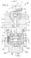
- the micrometric screw l05 incorporates a collar and is axially maintained and radially supported in relation to the body of the micrometric device l00 by way of two series of balls lO6 and their spacer rings l06a.
- the spacer rings lO6a, with the series of balls lO6 arranged therein, are anchored inside the body of the micrometric device lOO by way of support rings lO7, 107a and lO7b.
- an intermediate ring lO7a is arranged between an upper ring l07 and a lower ring lO7b.
- the upper ring lO7 is provided with a chamfer at its internal lower edge such that the chamfer, together with a rest of a right angle formed on an upper portion of the collar of micrometric device lO5, provides a radial and axial support for the balls lO6 lodged between the chamfer of ring 1O7 and the right angle rest of the collar.
- An upper surface of the lower ring lO7b provides together with a lower face of the collar of the micrometric screw lO5, a second axial support for the balls lO6 retained between the faces of the lower ring lO7b and the collar of the micrometric screw lO5. In this way, the upper and lower rings complete a support system for supporting the micrometric screw lO5 in relation to the body of the micrometric device lOO.
- the support system comprising the balls lO6, the spacer rings lO6a, and the rings lO7, lO7a and lO7b, is fixed by fastening screws lO8 to an upper body lOl which is shaped substantially as a cylindrical hollow body as shown in Figure 2.
- the upper body lOl is attached to a complementary lower cylindrical body lO2 by fastening screws lO3 as shown in Figure 3, so as to form a single body assembly coaxially mounted around, and housing, the micrometric screw lO5.
- the graduated drum lO4 is incorporated in, and coaxial with, the cylindrical hollow body lOl, lO2 formed thereby.
- the micrometric device lOO is provided with external threads lO2a at a free edge of the lower cylindrical body lO2.
- the micrometric device lOO can be threaded to a machine tool mandrel (not shown) by means of these external threads lO2a.
- the lower end of the micrometric screw lO5 is provided with a nut lO5a for holding the graduated drum lO4 in proximity to a shoulder lO5c of the micrometric screw 105.
- a thread lO5b is provided on an upper extension of the micrometric screw lO5 inside the upper cylindrical body lOl. Thread lO5b coaxially trespasses through, and engages with, a lower bushing 21 and an upper busing 22.
- the upper bushing 22 and lower bushing 21 are provided with internal and external threads which trespass coaxially through, and engage with, an indented cylindrical rod 20 slidably lodged in a coaxial hole of the upper cylindrical body lOl.
- the indented cylindrical rod 20, together with the lower bushing 21 and the upper bushing 22, comprise one single assembly coaxially mounted around the upper portion or extension of the micrometric screw lO5.
- the assembly is arranged inside the interior of the upper cylindrical body lOl as shown in Figure 2.
- the construction of the indented rod 20 and bushings 21 and 22 enables the bushings to convert rotating movement of the graduated drum l04, which is transmitted to the micrometric screw l05, into linear movement of the cylindrical rod 20.
- the linear movement of the rod 20 is arranged to displace a pair of concentric rods 23 and 24 shown in Figures 2 and 3.
- the rods 23, 24 are arranged substantially perpendicular to the longitudinal or geometric axis of the micrometric screw lO5.
- the upper bushing 22 functions to suppress or substantially remove any backlash between active thread flanks of the micrometric screw lO5 and active thread flanks of the lower bushing 21.
- active flanks indicates those flanks of a thread which interact with flanks of another thread.
- the backlash suppression function is performed in a controlled manner in that the upper bushing 22 is provided with an internal thread 22a and an external thread 22b which have different pitches, that is, the pitch of the external thread 22b of the upper bushing 22 differs from that of the internal thread 22a of the upper bushing 22.
- the internal thread 22a of the upper bushing engages with the micrometric screw lO5 and therefore the pitch of the internal thread 22a is equal to the pitch of the thread of the micrometric screw lO5.
- the relative displacement between the upper bushing 22 and the cylindrical rod 20 is equal to the difference between the pitches of internal thread 22a and external thread 22b of the upper bushing 22.
- the backlash suppression system also comprises a nut 25 arranged around an upper extreme edge of the upper bushing 22. Nut 25 locks the upper bushing 22 in a set position to maintain a zero or null backlash condition between the active flanks of the thread of the upper bushing 22, the thread of the lower bushing 21 and the thread of the micrometric screw l05 as shown in Figure 2a.
- the cylindrical rod 20 incorporates a plane portion contained on an imaginary, dimensional plane substantially parallel to its geometric or longitudinal axis.
- the plane portion is provided with rectilinear teeth 20a which are oriented at an angle ⁇ relative to the geometric or longitudinal axis of the rod 20.
- the geometric axis of the rod 20 coincides with the geometric axis of the micrometric screw lO5.
- the rectilinear teeth 20a are formed by converging flanks which mate with teeth 23a and 24a arranged on the plane portion of each one of the concentric rods 23 and 24.
- the teeth 23a, 24a on rods 23, 24 are formed of converging flanks.
- the plane portion of each concentric rod is contained on the same imaginary plane and is arranged substantially parallel to the geometric axis of those rods.
- the plane portion of each rod 23, 24 coincides with the imaginary plane that contains the plane portion of the cylindrical rod 20.
- the rod 24 is arranged in the interior of rod 23.
- Rod 23 has a terminal 30 arranged at one side.
- Terminal 30 is provided with a thread 30a which interacts with a screw 31 lodged in the terminal 30.
- Screw 31 holds an ear, or projection, lOa of the crossbeam lO.
- Ear lOa is held between a portion of the terminal 30 and a washer 32 by the action of the screw 31.
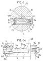
- rod 24 On the opposite side of the pair of concentric rods 23 and 24, rod 24 has a terminal 33 which is provided with an external thread.
- a bushing 34 has an internal thread 34b which engages with the threading on terminal 33.
- Bushing 34 also has an external thread 34a which has a different pitch than that of the internal thread 34b.
- the external thread 34a of the bushing 34 has a pitch different from the pitch of its internal thread 34b which is equal to the pitch of the thread of terminal 33.
- This arrangement has a double purpose, that is, to enable an ultra fine adjustment of the relative displacement to be made between the concentric rods 23 and 24, and also to enable the suppression of backlash between the teeth 20a of cylindrical rod 20 and the teeth 23a and 24a of the concentric rods 23 and 24, respectively. This is achieved by guaranteeing a metal to metal contact as described in GB-A-2250459.
- the micrometric device illustrated further comprises a nut 35 arranged on the external thread 34a of the bushing 34.
- the nut 35 functions to maintain the preestablished conditions of zero backlash substantially constant by adjustment of the bushing 34.
- Figure 4a shows the locking action of nut 35 actuating simultaneously against bushing 34 and rod 23 to ensure the zero backlash condition between the active flanks of the assembly.
- the movable crossbeam lO acts as a slidable support for tool shanks ll, lla and moves under the guidance of two rows of balls 40 which roll, with minimum friction and without play, on linear and parallel tracks, or guideways.
- These guideways are substantially V-shaped and are provided on the walls of a recess existing on the upper portion of upper body lOl and on the sides of the movable crossbeam l0.
- the recess extends from one side to the other in the upper portion of upper body lOl in a direction substantially perpendicular to the geometric axis of the micrometric screw lO5.
- the movable crossbeam lO is also displaceable substantially perpendicularly to the geometric axis of the micrometric screw lO5.
- the displacement of the movable crossbeam lO is achieved in an extremely stable way (without rocking) because the movable crossbeam lO rests on three points. Two of the points are formed by the balls 40 lodged in the V-shaped guideways and the third point is comprised by the connection of the ear l0a of the movable crossbeam lO to the terminal 30 of the concentric rod 23.
- the free end of the graduated drum l04 is provided with a plurality of teeth l2l and spaces l22 arranged between the teeth l2l. At least one pair of locating pins l23 actuate on the teeth l2l. A free end of each locating pin l23 is preferably engaged in one space between any two teeth l2l and/or on the crest of any teeth. Thus, if one of the locating pins is engaged in a space between two teeth, the free end of the other locating pin will rest on a crest of another one of the teeth l2l. In order to prevent the locating pins l23 from interfering with one another, the locating pin which is resting on the crest of one of the teeth is not one of the two teeth which define the space therebetween in which the other locating pin is positioned.
- the action of springs l24 on the locating pins l23 is directed to establish a condition of resilient pressure such that the locating pins l23 actuate and perform their inherently effective function as locating pins for the graduated drum lO4.
- the locating pins will provide adequate angular positioning for the drum lO4 and at the same time prevent an accidental adjustment change of the angular position previously made.
- a gap is defined between the position of the locating pins l23 and the spaces l22 in such a manner so as to generate a duplicity of stages of radial displacement of the graduated drum lO4. Therefore, the second locating pin l23 is positioned at an angular distance of a half pitch larger or smaller than a complete quantity of pitches so that before the first pin l23 reaches a new position after rotation l/n, the set of spaces l22 is located and actuated by the second pin l23.
- the fraction l/n corresponds to one nth, where n is the number of spaces and defines the pitch which is equal to the interval between two consecutive spaces.
- each half pitch is equal to the faction 2/n, or two nth, which in turn corresponds to oneractionor division) of the graduated drum lO4.
- the number of locating pins in the device of the present invention may be more than two pins 123. In one embodiment, for example, four locating pins l23 may be used wherein two of the locating pins l23 are positioned on the crest of any teeth l21 and between spaces l22 not occupied by the remaining two locating pins.
- manual access to the graduated drum lO4 is through lateral openings lO2b provided in the lower body lO2 which permit normal rotation of the graduated drum lO4.
- the rotation of graduated drum lO4 can also be made by several external non-manual actuating means (not shown).
- a drum lO4 is used which is capable of receiving movements from the external actuating means.
- Tool shanks ll and lla are held on the crossbeam lO by juxtaposition of dovetail parts arranged on the upper surface of the crossbeam lO and on the lower surface of the tool shank ll and lla.
- the parts on the crossbeam are male, whilst the parts on the tool shank are female and correspond to the male parts to ensure an adequate fit.
- Figures l, 7, and 7a show a safety device to prevent the tool shank ll and lla from loosening up when subject to a centrifugal force. This is achieved by introducing a threaded stud 50 that presses against a safety pin 5l provided with a toothed terminal 5l' which engages on teeth 52 located on the upper surface of the crossbeam l0.
- the tool shank ll, lla is provided with screws 53 that hold the tool shank ll, lla in a secure position by tightening it against the crossbeam lO and allow also the pre-positioning of the tool shank ll, lla in accordance with the bore diameter to be finished by the micrometric device lOO.
- the device also comprises a threaded hole 54 which is provided with a threaded plug 54a.
- the hole 54 provides access to a normal tool in the event an adjustment of the upper bushing 22 is required as the upper bushing 22 suppresses mechanical backlash as described and shown in Figure 2a.
Landscapes
- Engineering & Computer Science (AREA)
- Mechanical Engineering (AREA)
- Transmission Devices (AREA)
- Cutting Tools, Boring Holders, And Turrets (AREA)
- Dental Tools And Instruments Or Auxiliary Dental Instruments (AREA)
Applications Claiming Priority (3)
| Application Number | Priority Date | Filing Date | Title |
|---|---|---|---|
| BR929204014A BR9204014A (pt) | 1992-10-08 | 1992-10-08 | Aperfeicoamento em dispositivo micrometrico para regualgem de ferramenta para acabamento de furos de alta precisao |
| BR9204014 | 1992-10-08 | ||
| EP93308021A EP0593222B1 (fr) | 1992-10-08 | 1993-10-08 | Améliorations dans des dispositifs micrométriques pour la finition de trous de précision |
Related Parent Applications (1)
| Application Number | Title | Priority Date | Filing Date |
|---|---|---|---|
| EP93308021.0 Division | 1993-10-08 |
Publications (3)
| Publication Number | Publication Date |
|---|---|
| EP0640421A2 true EP0640421A2 (fr) | 1995-03-01 |
| EP0640421A3 EP0640421A3 (fr) | 1995-05-03 |
| EP0640421B1 EP0640421B1 (fr) | 1996-11-20 |
Family
ID=4055096
Family Applications (2)
| Application Number | Title | Priority Date | Filing Date |
|---|---|---|---|
| EP94116312A Expired - Lifetime EP0640421B1 (fr) | 1992-10-08 | 1993-10-08 | Améliorations dans ou en rélation avec des dispositifs micrométriques pour la finition de trous de précision |
| EP93308021A Expired - Lifetime EP0593222B1 (fr) | 1992-10-08 | 1993-10-08 | Améliorations dans des dispositifs micrométriques pour la finition de trous de précision |
Family Applications After (1)
| Application Number | Title | Priority Date | Filing Date |
|---|---|---|---|
| EP93308021A Expired - Lifetime EP0593222B1 (fr) | 1992-10-08 | 1993-10-08 | Améliorations dans des dispositifs micrométriques pour la finition de trous de précision |
Country Status (7)
| Country | Link |
|---|---|
| US (1) | US5316417A (fr) |
| EP (2) | EP0640421B1 (fr) |
| JP (2) | JP2736399B2 (fr) |
| BR (1) | BR9204014A (fr) |
| CH (1) | CH683894A5 (fr) |
| DE (1) | DE4332520C2 (fr) |
| FR (1) | FR2696666B1 (fr) |
Cited By (1)
| Publication number | Priority date | Publication date | Assignee | Title |
|---|---|---|---|---|
| WO2012038158A1 (fr) * | 2010-09-24 | 2012-03-29 | Komet Group Gmbh | Tête d'outil pour une utilisation dans des machines-outils |
Families Citing this family (25)
| Publication number | Priority date | Publication date | Assignee | Title |
|---|---|---|---|---|
| WO1995007160A1 (fr) * | 1993-09-11 | 1995-03-16 | Komet Präzisionswerkzeuge Robert Breuning Gmbh | Tete d'outil, notamment tete d'outil de surfacage |
| DE19517365B4 (de) * | 1995-05-11 | 2004-09-16 | Wohlhaupter Gmbh | Werkzeughalter |
| US5735649A (en) * | 1996-10-08 | 1998-04-07 | Kaiser Precision Tooling, Inc. | Machine tool cutter position adjustment device |
| US5971675A (en) * | 1997-08-12 | 1999-10-26 | Industrias Romi, S.A. | Boring device |
| DE19845948A1 (de) | 1998-10-06 | 2000-04-20 | Bitrek Corp | Gewindeschneidvorrichtung |
| US7029209B2 (en) * | 2000-12-18 | 2006-04-18 | Cardemon, Inc. | Slidable boring tool with fine adjustment |
| BR0116267A (pt) * | 2000-12-18 | 2004-01-06 | Cardemon Inc Dba Car Tec Co | Método e aparelho de ajuste para uma ferramenta de perfuração |
| MXPA04010576A (es) * | 2002-04-25 | 2005-07-01 | Cardemon Inc | Herramienta perforadora deslizable con ajuste fino. |
| TWI357364B (en) * | 2005-04-26 | 2012-02-01 | Kaiser Heinz Ag | Boring tool |
| US7699567B2 (en) * | 2006-11-07 | 2010-04-20 | Sandvik, Inc. | Final adjustment mechanism with tactile feedback |
| US8469639B2 (en) * | 2007-05-31 | 2013-06-25 | Valenite, Llc | Actuated material removal tool |
| US9050657B2 (en) * | 2007-07-05 | 2015-06-09 | Sandvik, Inc. | Actuated material removal tool |
| JP2009068686A (ja) * | 2007-08-23 | 2009-04-02 | Tokai Rika Co Ltd | 取付寸法調整部材 |
| US8327742B1 (en) * | 2008-03-07 | 2012-12-11 | Lockheed Martin Corporation | Diamond tool micro-height-adjuster within a multi-tool rotating head |
| WO2010009226A1 (fr) * | 2008-07-18 | 2010-01-21 | Valenite Llc | Outil d'alésage inverse avec actionnement par agent de refroidissement |
| CN102151879B (zh) * | 2011-02-23 | 2013-04-24 | 河海大学常州校区 | 可移动镗刀刀架 |
| US8727678B2 (en) * | 2011-09-14 | 2014-05-20 | Kennametal Inc. | Autobalancing system for boring tool and boring tool incorporating same |
| CN102500777B (zh) * | 2011-11-07 | 2014-02-26 | 厦门大学 | 一种外径可调与切刃可替换的单刃金刚石切削刀具 |
| AT13405U1 (de) * | 2012-01-20 | 2013-12-15 | Ceratizit Austria Gmbh | Hartwerkstoff-gewindeverbindung |
| CN104227048A (zh) * | 2014-09-02 | 2014-12-24 | 西安万威刀具有限公司 | 一种远端微调深孔反镗刀 |
| US9868158B2 (en) | 2014-10-03 | 2018-01-16 | Kennametal Inc. | Automatic balancing device for boring heads |
| BR102014026246B1 (pt) | 2014-10-21 | 2022-11-01 | Kennametal Inc | Cabeça de perfuração |
| US10076790B2 (en) | 2016-07-26 | 2018-09-18 | Kennametal Inc. | Ultra-precise boring cartridge and adjustment device therefor |
| US10569341B2 (en) * | 2018-07-30 | 2020-02-25 | Lintech | Contouring head |
| DE102019100890A1 (de) | 2019-01-15 | 2020-07-16 | Botek Präzisionsbohrtechnik Gmbh | Bohrkopf und Verfahren zum Auskesseln von Sackbohrungen |
Family Cites Families (16)
| Publication number | Priority date | Publication date | Assignee | Title |
|---|---|---|---|---|
| DE590390C (de) * | 1934-01-06 | Otto Buexenstein | Bohrvorrichtung | |
| DE664304C (de) * | 1933-03-19 | 1938-08-24 | Hans F Puchstein | In zwei aufeinander senkrecht stehenden Koordinatenebenen selbsttaetig einstellbare Reibahle |
| US2498870A (en) * | 1940-08-03 | 1950-02-28 | Kearney & Trecker Corp | Backlash compensator |
| BE461998A (fr) * | 1946-03-06 | |||
| DE853087C (de) * | 1950-05-26 | 1952-10-20 | Wiedemann Kommandit Ges | Bohr- und Abflaechstange |
| FR1389630A (fr) * | 1964-01-10 | 1965-02-19 | Dispositifs de transmission par vis et écrou à rattrapage de jeu | |
| DE1477252A1 (de) * | 1965-07-21 | 1969-06-04 | Siegfried Dietz | Feindrehgeraet |
| JPS5139909U (fr) * | 1974-09-18 | 1976-03-25 | ||
| US4516889A (en) * | 1982-09-07 | 1985-05-14 | Devlieg Machine Company | Precision adjustable cutting tool |
| US4648757A (en) * | 1982-11-18 | 1987-03-10 | Amca International Corporation | Precision adjustment system for boring tools |
| GB2142851B (en) * | 1983-05-16 | 1986-09-03 | Daishowa Seiki | Machine tool holder unit |
| DE3332243A1 (de) * | 1983-09-07 | 1985-03-21 | J. Kühn GmbH & Co Präzisionswerkzeug KG, 4270 Dorsten | Drehbare bearbeitungsvorrichtung, insbesondere ausbohrkopf o.dgl. |
| US4793748A (en) * | 1987-05-11 | 1988-12-27 | Amca International Corporation | Boring tool for machine tool |
| JPH045302U (fr) * | 1990-04-27 | 1992-01-17 | ||
| BR9006125A (pt) * | 1990-12-03 | 1991-06-11 | Romi Ind | Dispositivo micrometrico para regulagem de ferramenta para acabamento de furos de ultra precisao |
| DE4139650C2 (de) * | 1990-12-03 | 1995-03-30 | Romi Ind | Feinausbohrwerkzeug |
-
1992
- 1992-10-08 BR BR929204014A patent/BR9204014A/pt not_active IP Right Cessation
-
1993
- 1993-05-04 US US08/057,705 patent/US5316417A/en not_active Expired - Lifetime
- 1993-09-24 DE DE4332520A patent/DE4332520C2/de not_active Expired - Lifetime
- 1993-10-07 JP JP5277932A patent/JP2736399B2/ja not_active Expired - Lifetime
- 1993-10-07 FR FR9311958A patent/FR2696666B1/fr not_active Expired - Lifetime
- 1993-10-07 CH CH3020/93A patent/CH683894A5/fr not_active IP Right Cessation
- 1993-10-08 EP EP94116312A patent/EP0640421B1/fr not_active Expired - Lifetime
- 1993-10-08 EP EP93308021A patent/EP0593222B1/fr not_active Expired - Lifetime
-
1996
- 1996-08-12 JP JP8231327A patent/JP2824633B2/ja not_active Expired - Lifetime
Cited By (4)
| Publication number | Priority date | Publication date | Assignee | Title |
|---|---|---|---|---|
| WO2012038158A1 (fr) * | 2010-09-24 | 2012-03-29 | Komet Group Gmbh | Tête d'outil pour une utilisation dans des machines-outils |
| CN103097059A (zh) * | 2010-09-24 | 2013-05-08 | 彗星集团有限公司 | 在机床中使用的组合式刀盘 |
| CN103097059B (zh) * | 2010-09-24 | 2015-07-22 | 彗星集团有限公司 | 在机床中使用的组合式刀盘 |
| US9162291B2 (en) | 2010-09-24 | 2015-10-20 | Komet Group Gmbh | Tool head for use in machine tools |
Also Published As
| Publication number | Publication date |
|---|---|
| DE4332520C2 (de) | 1996-04-11 |
| DE4332520A1 (de) | 1994-04-21 |
| FR2696666B1 (fr) | 1994-12-16 |
| EP0640421B1 (fr) | 1996-11-20 |
| JP2736399B2 (ja) | 1998-04-02 |
| FR2696666A1 (fr) | 1994-04-15 |
| CH683894A5 (fr) | 1994-06-15 |
| BR9204014A (pt) | 1993-02-24 |
| JP2824633B2 (ja) | 1998-11-11 |
| US5316417A (en) | 1994-05-31 |
| EP0593222A1 (fr) | 1994-04-20 |
| EP0640421A3 (fr) | 1995-05-03 |
| JPH09168903A (ja) | 1997-06-30 |
| EP0593222B1 (fr) | 1995-06-21 |
| JPH06277908A (ja) | 1994-10-04 |
Similar Documents
| Publication | Publication Date | Title |
|---|---|---|
| EP0640421B1 (fr) | Améliorations dans ou en rélation avec des dispositifs micrométriques pour la finition de trous de précision | |
| DE19940330C2 (de) | Werkzeugspanneinrichtung | |
| EP1193027B1 (fr) | Tour | |
| DE3851443T2 (de) | System mit rotierenden paletten. | |
| EP1027955B1 (fr) | Machine-outil | |
| US4097180A (en) | Chaser cutting apparatus | |
| US4080854A (en) | Adjustable tool holder | |
| US20130168913A1 (en) | Zero point clamping device | |
| US5704742A (en) | Rotary tool | |
| DE2030870B2 (de) | Bohrkopf, der an der drehbaren Spindel einer Werkzeugmaschine befestigt ist | |
| EP0593223B1 (fr) | Dispositif micrométrique amélioré pour la finition de trous | |
| EP1638720B1 (fr) | Machine-outil a broches paralleles pouvant etre rapprochees | |
| US4896560A (en) | Indexing device | |
| EP1390792B9 (fr) | Systeme de positionnement | |
| DE3852309T2 (de) | Spannzange zum Halten eines Werkzeuges, insbesondere einer Schneidwerkzeuges. | |
| EP0381626B1 (fr) | Outil rotatif à aléser | |
| EP1514623B1 (fr) | Machine-outil et porte-outil associé | |
| DE19910953A1 (de) | Werkzeugmaschine | |
| DE1271501B (de) | Mehrspindel-Drehautomat | |
| SU1294513A1 (ru) | Резьбонарезна головка | |
| SU1710309A1 (ru) | Инструмент дл обработки отверстий | |
| SU1282971A2 (ru) | Расточна головка | |
| EP4119288A1 (fr) | Dispositif de correction des écarts de position d'une machine d'usinage | |
| DE3335022A1 (de) | Befestigungseinrichtung fuer werkzeuge an werkzeugmaschinen | |
| DE3733811A1 (de) | Grossrundstrickmaschine |
Legal Events
| Date | Code | Title | Description |
|---|---|---|---|
| PUAI | Public reference made under article 153(3) epc to a published international application that has entered the european phase |
Free format text: ORIGINAL CODE: 0009012 |
|
| 17P | Request for examination filed |
Effective date: 19941206 |
|
| AC | Divisional application: reference to earlier application |
Ref document number: 593222 Country of ref document: EP |
|
| AK | Designated contracting states |
Kind code of ref document: A2 Designated state(s): GB IT SE |
|
| PUAL | Search report despatched |
Free format text: ORIGINAL CODE: 0009013 |
|
| AK | Designated contracting states |
Kind code of ref document: A3 Designated state(s): GB IT SE |
|
| 17Q | First examination report despatched |
Effective date: 19950612 |
|
| GRAG | Despatch of communication of intention to grant |
Free format text: ORIGINAL CODE: EPIDOS AGRA |
|
| GRAH | Despatch of communication of intention to grant a patent |
Free format text: ORIGINAL CODE: EPIDOS IGRA |
|
| GRAH | Despatch of communication of intention to grant a patent |
Free format text: ORIGINAL CODE: EPIDOS IGRA |
|
| GRAA | (expected) grant |
Free format text: ORIGINAL CODE: 0009210 |
|
| AC | Divisional application: reference to earlier application |
Ref document number: 593222 Country of ref document: EP |
|
| AK | Designated contracting states |
Kind code of ref document: B1 Designated state(s): GB IT SE |
|
| ITF | It: translation for a ep patent filed | ||
| PLBE | No opposition filed within time limit |
Free format text: ORIGINAL CODE: 0009261 |
|
| STAA | Information on the status of an ep patent application or granted ep patent |
Free format text: STATUS: NO OPPOSITION FILED WITHIN TIME LIMIT |
|
| 26N | No opposition filed | ||
| REG | Reference to a national code |
Ref country code: GB Ref legal event code: IF02 |
|
| PGFP | Annual fee paid to national office [announced via postgrant information from national office to epo] |
Ref country code: IT Payment date: 20121011 Year of fee payment: 20 Ref country code: SE Payment date: 20121011 Year of fee payment: 20 Ref country code: GB Payment date: 20121003 Year of fee payment: 20 |
|
| REG | Reference to a national code |
Ref country code: GB Ref legal event code: PE20 Expiry date: 20131007 |
|
| REG | Reference to a national code |
Ref country code: SE Ref legal event code: EUG |
|
| PG25 | Lapsed in a contracting state [announced via postgrant information from national office to epo] |
Ref country code: GB Free format text: LAPSE BECAUSE OF EXPIRATION OF PROTECTION Effective date: 20131007 |