EP0640445B1 - Outil à enfoncer des attaches actionné par ressort - Google Patents
Outil à enfoncer des attaches actionné par ressort Download PDFInfo
- Publication number
- EP0640445B1 EP0640445B1 EP94110760A EP94110760A EP0640445B1 EP 0640445 B1 EP0640445 B1 EP 0640445B1 EP 94110760 A EP94110760 A EP 94110760A EP 94110760 A EP94110760 A EP 94110760A EP 0640445 B1 EP0640445 B1 EP 0640445B1
- Authority
- EP
- European Patent Office
- Prior art keywords
- spring means
- driving tool
- fastener driving
- handle
- power spring
- Prior art date
- Legal status (The legal status is an assumption and is not a legal conclusion. Google has not performed a legal analysis and makes no representation as to the accuracy of the status listed.)
- Expired - Lifetime
Links
- 230000000694 effects Effects 0.000 claims description 4
- 230000002093 peripheral effect Effects 0.000 claims description 4
- 230000013011 mating Effects 0.000 claims description 3
- 239000000463 material Substances 0.000 claims description 2
- 238000006073 displacement reaction Methods 0.000 claims 1
- 238000004519 manufacturing process Methods 0.000 description 3
- 230000009286 beneficial effect Effects 0.000 description 2
- 239000002184 metal Substances 0.000 description 2
- 238000003466 welding Methods 0.000 description 2
- DHKHKXVYLBGOIT-UHFFFAOYSA-N 1,1-Diethoxyethane Chemical compound CCOC(C)OCC DHKHKXVYLBGOIT-UHFFFAOYSA-N 0.000 description 1
- JOYRKODLDBILNP-UHFFFAOYSA-N Ethyl urethane Chemical compound CCOC(N)=O JOYRKODLDBILNP-UHFFFAOYSA-N 0.000 description 1
- 238000013016 damping Methods 0.000 description 1
- 230000001419 dependent effect Effects 0.000 description 1
- 230000000994 depressogenic effect Effects 0.000 description 1
- 238000010586 diagram Methods 0.000 description 1
- 230000009977 dual effect Effects 0.000 description 1
- 210000005069 ears Anatomy 0.000 description 1
- 230000003993 interaction Effects 0.000 description 1
- 238000000034 method Methods 0.000 description 1
- 201000002266 mite infestation Diseases 0.000 description 1
- 238000002360 preparation method Methods 0.000 description 1
- 238000003825 pressing Methods 0.000 description 1
- 239000012858 resilient material Substances 0.000 description 1
- 230000000284 resting effect Effects 0.000 description 1
- 238000000926 separation method Methods 0.000 description 1
- 210000001364 upper extremity Anatomy 0.000 description 1
Images


Classifications
-
- B—PERFORMING OPERATIONS; TRANSPORTING
- B25—HAND TOOLS; PORTABLE POWER-DRIVEN TOOLS; MANIPULATORS
- B25C—HAND-HELD NAILING OR STAPLING TOOLS; MANUALLY OPERATED PORTABLE STAPLING TOOLS
- B25C5/00—Manually operated portable stapling tools; Hand-held power-operated stapling tools; Staple feeding devices therefor
- B25C5/10—Driving means
- B25C5/11—Driving means operated by manual or foot power
-
- B—PERFORMING OPERATIONS; TRANSPORTING
- B25—HAND TOOLS; PORTABLE POWER-DRIVEN TOOLS; MANIPULATORS
- B25C—HAND-HELD NAILING OR STAPLING TOOLS; MANUALLY OPERATED PORTABLE STAPLING TOOLS
- B25C5/00—Manually operated portable stapling tools; Hand-held power-operated stapling tools; Staple feeding devices therefor
- B25C5/06—Manually operated portable stapling tools; Hand-held power-operated stapling tools; Staple feeding devices therefor without provision for bending the ends of the staples on to the work
Definitions
- the invention relates to a spring actuated fastener driving tool with the features cited in the preamble of claim 1.
- a spring actuated fastener driving tool of this type is disclosed in US-A-4,452,388. Basically, this driving tool operates satisfactorily. During the movement of the handle, the spring means is deflected and a pin which rotatably holds the pawl means moves along an arc which initially extends upwardly and forwardly. The relatively high level of force required to cycle the tool is of particular concern since it can result in worker fatigue and loss of production efficiency.
- Another spring actuated fastener driving tool is disclosed in GB-A-646,222.
- This tool has a handle which is pivotably mounted on a housing.
- a trigger lever is rotatably mounted on the front end of the handle.
- the trigger lever has a hook which engages with a hammer 8 and a rest position.
- the hammer 8 is connected to a driver element for ejecting the fasteners.
- the hook portion engages the hammer in the above-mentioned rest position and intermediate position. In the release position, the hook is deflected and releases the hammer so that a vertically arranged actuating coil spring is allowed to exert its resilient force on the hammer member to eject the fastener.
- lift pawls are pivotable about a first axis into and out of engagement with a power spring assembly responsible for generating the fastener driving force.
- the lift paws are in turn connected to an operating handle which is pivotable about a parallel second axis through successive driving cycles, each including a loading phase during which the pawls remain engaged with the power spring assembly as the latter is resiliently deflected and loaded, and a release phase during which the pawls are disengaged from the power spring assembly, thereby allowing the power spring assembly to act through an associated driver to drive a fastener into or through a work surface.
- the first axis is defined by a bearing which is appropriately mounted and guided for movement towards the second axis during each loading phase, the result being a beneficial increase in mechanical advantage with an attendant lessening in the force required to operate the handle through successive drive cycles.
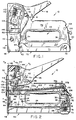
- FIG. 10 there is shown at 10 an embodiment of a spring actuated fastener driving tool according to the present invention.
- the tool is adapted to drive U-shaped staples 12 releasably interconnected in an elongated assembly indicated generally at 14 and typically referred to as a "stick".
- the tool may be modified without departing from the scope of the invention to drive other types of fasteners, including for example brads, nails and the like.
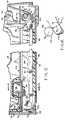
- the tool includes a basic housing comprising a mating pair of stamped sheet metal sides 16a, 16b appropriately shaped to define a head portion 18 and a base portion 20 with a finger opening 22 extending therethrough.
- An inner body 24 is positioned between the sides 16a, 16b in the base portion 20 of the housing.
- the inner body is preferably molded of a plastic material, typically DUPONT DELRIN 100 or the like.
- the inner body is provided at its forward end with a resilient cantilevered leg 26, and at its rearward end with a second resilient cantilevered leg 28 spaced inwardly from a rearwardly protruding boss 30.
- the boss 30 is straddled by the parallel legs 32a of a U-shaped spring bracket 32 having a depending tab 32b struck from its bight section 32c.
- the sides 16a, 16b and the inner body 24 are interconnected by rivets 34, 36 or the like extending therethrough, with the rivet 36 additionally serving to join the spring bracket 32 to the boss 30 as part of this basic housing assembly.
- a nose cap 38 is fitted over the sides at the forward end of the housing. The nose cap is latched under the enlarged exposed heads of a handle pivot pin 40, and is secured in place by a third fastener, typically a pin 42 held in place by a conventional E-ring (not shown).
- the forward end of the inner body 24 cooperates with the sides 16a, 16b and the interior front surface 44 of the nose cap 38 to define a drive track 46 contained in a first reference plane P a and leading to an exit opening 48.
- a driver 50 is reciprocally mounted in the drive track 46.
- the forward leg 26 of the inner body serves to resiliently bias the driver 50 against the interior front surface 44 of the nose cap 38.
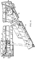
- a magazine assembly generally indicated at 52 is located along the underside of the tool.
- the magazine assembly includes an inverted generally channel shaped magazine shell 54 having an L-shaped 56 finger at its forward end received in a complimentary slot in the underside of the inner body 24.
- the rear end of the magazine shell has an aperture 58 in its bight section spaced inwardly from a rearwardly extending horizontal Mange 60.
- the resilient rear leg 28 of the inner body 24 snaps into the aperture 58 and serves to resiliently bias the magazine shell 54 forwardly into contact with the interior front surface 44 of the nose cap 38.
- a channel-shaped metal shoe 70 is pivotally connected to the lower rear end of the housing by a pin 72 extending through elongated openings 74 in the sides 16a, 16b.
- a shoe spring 76 encircles the pin 72 and has angularly extending legs coacting resiliently with a rear housing wall 78 and the bight section 80 of the shoe.
- the forward end of the shoe 70 has a nose 82 (see Figure 1) in latched engagement as at 84 with shoulders on the nose cap 38.
- the shoe spring 76 coacts with the rear housing wall 78 and the pin 72 to resiliently hold the shoe in closed latched engagement with the nose cap.
- the shoe 70 is pushed rearwardly against the biasing action of the shoe spring 76, thereby unlatching the nose 82 as the pin 72 is pushed rearwardly in elongated openings 74.
- the shoe is then swung open about pin 72 as shown in Figure 14.
- a core 86 is carried on the shoe 70.
- the shoe 70 has L-shaped fingers 88 struck from its bight section which coact with complimentary recesses in the core to hold the core in place.
- the magazine shell 54 and the core 86 cooperate, when the shoe is in its closed latched position, to define a guide channel 90 for the staple stick 14 and for the pusher 68.
- a pusher spring 92 is connected at one end to a tab 94 struck from the bight section of the pusher 68.
- Spring 92 extends forwardly around a cross pin 98 at the forward end of the core 86 and then rearwardly for connection at its opposite end to a tab 100 struck from the bight section of the shoe 70.
- the pusher spring 92 biases the pusher 68 forwardly, thereby urging a stick 14 of staples or the like in the same direction.
- the end most staple 12a is urged against the back side of the driver 50 when the driver is located in the position shown, for example, in Figures 2 and 12.
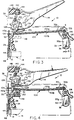
- a power spring assembly generally indicated at 102 is located in the upper area of the housing base portion 20.
- Spring assembly 102 includes upper and lower superimposed leaf springs 102a, 102b.
- Lower leaf spring 102b has a nose at its forward end protruding into interlocked engagement in an opening 104 in the upper end of driver 50.
- the rear end of the spring assembly 102 extends beneath the bight section 32c of the spring bracket 32, and the lower leaf spring 102b rests on an adjustment lever 106 pivotally supported between the legs 32a of the spring bracket by a pin 108.
- the tab 32b struck from the bight section of the spring bracket extends downwardly into aligned apertures in the springs, thereby serving to locate the springs longitudinally within the housing.
- the adjustment lever 106 has an eccentric portion which can be rotated in a known manner to vary spring driving power.
- a pair of pawls 110 are carried on a lift bearing 112 for pivotal movement about a shiftable axis of rotation A s .
- the pawls have extensions 110a, 110b extending respectively downwardly and rearwardly with respect to axis A s .
- the downward extensions 110a have shoulders 114 adapted to coact in latched engagement with the lower leaf spring 102b.
- a handle assembly 116 is mounted for pivotal movement about a fixed axis of rotation A f defined by the handle pin 40 extending between the side 16a, 16b. As depicted in Figure 2, axis A f is contained in a second reference plane P b parallel to reference plane P A .
- the handle assembly 116 includes an interiorly protruding bifurcated portion with spaced walls 118 interrupted by arcuate slots 120.
- the upper and lower arcuate edges of the slots 120 are received respectively in upper and lower arcuate grooves 122 in enlarged diameter portions 124 of the lift bearing 112.
- the reduced diameter ends 126 of the lift bearing are journalled for rotation about axis A s in slide members 128.
- the slide members 128 are in turn arranged to move reciprocally indicated schematically at "x" in Figure 1 within angularly disposed windows 130 in the housing sides 16a, 16b.
- a spring anchor 132 extends between and has a bottom edge resting on offset radial surfaces 136 of the lift pawls.
- the spring anchor has ends received in notches 138 in the slide members 128, and upwardly protruding fingers 140 received in the lower ends of return springs 142.
- the upper ends of the springs 142 in turn are received in bores 144 extending through a handle stop 146 located in the head portion of the housing.
- the return springs 142 bias the pawls 110 into counterclockwise rotation (as viewed for example in Figure 2) about axis A s , thereby insuring that the downward pawl extensions 110a are resiliently urged into latched engagement with the lower leaf spring 102b.
- the forward end of the spring assembly 102 is supported on a bumper 148 located in a pocket 150 at the forward end of the inner body 24.
- the bumper 148 is integrally molded of a resilient material, e.g., urethane, and has a vibration damping element in the form of a hollow inverted cone 152 spaced inwardly from and surrounded by a peripheral wall 154. In its unstressed state, as depicted in Figure 4, the cone 152 extends upwardly above the top edge of the peripheral wall 154.
- a resilient material e.g., urethane
- the handle assembly has been pivoted in a clockwise direction to an intermediate position at which it has acted through the lift bearing 112 and the pawls 110 to resiliently deflect and load the power spring assembly 102, with an accompanying retraction of the driver 50 from the forward end of the magazine.
- the driver 50 is resiliently biased against the same interior front surface by the resilient leg 26 of the inner body 24, thereby insuring alignment of the driver 50 with staple 12a.
- the present invention offers a number of significant advantages over conventional spring actuated fastener driving tools. Most significantly is the interaction of the handle assembly 116, lift bearing 112 and pawls 110 in conjunction with movement of the slide members 128 in the housing windows 130 to provide greater motion at reduced mechanical advantage in the early stages of the stroke when power spring resistance is at its minimum, followed by an exertion of maximum force at reduced handle pressure as the power spring assembly reaches its fully loaded position.
- the spring bracket 32 which holds and positions the leaf springs 102a, 102b of the power spring assembly 102, and in doing so receives the highest internal loads developed during the spring stressing stroke.
- This arrangement allows the main housing components 16a, 16b to be used without first being heat treated, thereby facilitating manufacturing and simplifying assembly by avoiding distortion and subsequent necessary adjustments.
- the engagement of the downwardly bent tab 32b of the spring bracket in the aligned apertures of the power leaf springs 102a, 102b provides accurate horizontal positioning of the front edge of the lower spring 102b where it is engaged by the lift pawls.
- the spring bracket 32 and its associated adjustment lever 106 also provide a convenient means for varying the driving power being generated by the power spring assembly 102.
- the inner body 24 is sandwiched between the two housing sides 16a, 16b together with the spring bracket 32. These components are rivetted together as a single assembly which becomes the unit onto which all other components are assembled.
- the rivetting operation is the only permanent fastening performed, and is designed to be part of a "final" assembly procedure, so that no interim subassemblies are created. This approach significantly aids in ease of manufacture and assembly by avoiding the traditional welding and rivetting of subassemblies.
- the biasing action of the resilient cantilevered front leg 26 of the inner body on the driver 50 insures that the driver is always properly aligned with the lead staple advanced into the drive track 46. This provides maximum clearance for the next adjacent staple in the stick and thereby insures a clean separation of the lead staple during the driving stroke.
- This biasing action also serves to dampen driver vibration as the power spring assembly 102 comes to rest on the bumper 148.
- the vibration dampening cone 152 on the bumper further serves to avoid annoying and potentially damaging power spring vibration.
- the cantilevered resilient rear leg 28 of the inner body serves two purposes. First, it facilitates assembly by allowing the finger 56 at the forward end of the magazine shell to be hooked into the complimentary recess in the inner body and then allowing the opening 58 at the rear end of the magazine shelf to be snapped onto the leg 28. Secondly, when the nose cap 38 is assembled onto the housing, the magazine shell will be pushed slightly against the resilient bias of leg 28 so as to produce a firm contact between the interior front surface 44 of the nose cap and the front edges of the magazine shell.
- the attachment of the core to the shoe by means of the finger/recess engagement avoids welding and also accommodates the possibility of interchanging different sized cores in order to accommodate various fastener sizes.
- the handle stop conveniently serves a dual function of a return spring housing, and is engageable by the handle assembly at both extremes of its pivotal motion.
Landscapes
- Engineering & Computer Science (AREA)
- Mechanical Engineering (AREA)
- Portable Nailing Machines And Staplers (AREA)
Claims (14)
- Outil (10) à enfoncer des agrafes actionné par ressort, comprenant :un corps (16a, 16b) comportant un magasin (52) destiné à contenir un ensemble de forme oblongue d'agrafes (12) reliées entre elles de façon détachable, ledit magasin ayant une extrémité avant et un couloir d'entraínement (46) qui s'étend au-delà de ladite extrémité avant, jusqu'à un orifice de sortie (48) ;des moyens de poussée associés audit magasin (52) destinés à pousser, en direction de ladite extrémité avant, un ensemble d'agrafes (12), qui sont contenues dans celui-ci ;un élément d'entraínement (50) monté en vue d'un déplacement en va-et-vient le long dudit couloir d'entraínement (46) ;un moyen (102) formant ressort de force, de forme oblongue, destiné à déplacer en va-et-vient ledit élément d'entraínement (50), ledit moyen (102) formant ressort de force étant ancré à l'une de ses extrémités par rapport audit corps et étant relié à l'extrémité opposée audit élément d'entraínement (50) ;un moyen (112) formant palier destiné à déterminer un premier axe de rotation (As) ;un moyen (110) formant cliquet destiné à relier de façon libérable ledit moyen (112) formant palier audit moyen (102) formant ressort, ledit moyen (110) formant cliquet étant porté par ledit moyen (112) formant palier, en vue d'un déplacement par pivotement sur ledit premier axe (As) avec mise en prise et mise hors de prise avec ledit moyen (102) formant ressort de force ;un moyen (142) formant ressort de rappel, destiné à pousser ledit moyen (110) formant cliquet jusqu'à ce qu'il vienne en prise avec ledit moyen (102) formant ressort de force ;une poignée (116) montée sur ledit corps (16) en vue de pivoter sur un second axe de rotation (Af) parallèle audit premier axe, ledit premier axe (As) étant situé entre, respectivement, le premier et le second plans de référence parallèles (Pa, Pb) contenant ledit couloir d'entraínement (46) et ledit second axe, ladite poignée (116) pouvant être mise en pivotement sur ledit second axe (Af) par l'intermédiaire de cycles d'entraínement successifs comprenant chacun :caractérisé en ce quea. une position de repos dans laquelle ledit élément d'entraínement (50) s'étend en travers de l'extrémité avant dudit magasin afin de ménager une butée contre laquelle l'agrafe (12) située tout à l'extrémité dudit ensemble est poussée par ledit moyen de poussée (92) ;b. une position intermédiaire, agissant à l'aide dudit moyen (112) formant palier et dudit moyen (110) formant cliquet, en prise avec ledit moyen (102) formant ressort de force afin de dévier élastiquement et de bander ledit moyen (102) formant ressort de force, avec une rétraction concomitante dudit élément d'entraínement (50) à l'écart de l'extrémité avant dudit magasin, afin, de ce fait, de permettre à ladite agrafe située tout à l'extrémité (12) d'avancer dans ledit couloir d'entraínement (46) ; etc. une position de libération, dans laquelle ledit moyen (110) formant cliquet est dégagé dudit moyen (102) formant ressort, ledit moyen formant ressort se trouvant ainsi libéré et exerçant sa force élastique sur ledit élément d'entraínement (50) dans la direction de rappel jusqu'à ce qu'il se retrouve en position de repos, afin d'éjecter une agrafe (12) dans ledit couloir d'entraínement (46), hors dudit corps, par ledit orifice de sortie (48) ,ledit moyen formant palier comprend un palier de soulèvement (112) qui est supporté de façon mobile par le corps (16a, 16b) ;ladite poignée (116) peut être mise en prise de façon continue avec le palier de soulèvement (112) ;ledit moyen (132, 142) formant ressort de rappel est associé au corps (16a, 16b) ;le corps et la poignée sont munis de surfaces de guidage (120, 130) qui coopèrent avec le palier de soulèvement (112) pour faciliter le déplacement du palier de soulèvement en direction du second plan de référence (Pb), en réaction au mouvement de pivotement de ladite poignée (116), de ladite position de repos à ladite position de libération.
- Outil à enfoncer des agrafes selon la revendication 1, dans lequel lesdites surfaces de guidage (120) comprennent une piste courbe sur ladite poignée (116).
- Outil à enfoncer des agrafes selon la revendication 2, dans lequel ledit moyen (112) formant palier avance sur ladite piste courbe (120) en réaction au mouvement de pivotement de ladite poignée (116) sur ledit second axe (Af).
- Outil à enfoncer des agrafes selon la revendication 2 ou 3, comprenant, en outre, un moyen d'arrêt (156) sur ladite poignée (116), ledit moyen (110) formant cliquet pouvant être mis en rotation par rapport à ladite poignée (116) pendant le déplacement de ladite poignée à partir de ladite position de repos, en passant par ladite position intermédiaire, et étant susceptible d'être mis en prise avec ledit moyen d'arrêt (156) afin de réaliser le dégagement dudit moyen (110) formant cliquet d'avec ledit moyen (102) formant ressort de force, dans ladite position de libération.
- Outil à enfoncer des agrafes selon la revendication 4, dans lequel ledit moyen (110) formant cliquet comporte des première et seconde parties en saillie (110a, 110b) disposées en formant un angle, lesdites premières parties en saillie (110a) pouvant être mises en prise de façon libérable avec ledit moyen (102) formant un ressort de force de forme oblongue et lesdites secondes parties en saillies (110b) pouvant être mises en prise avec ledit moyen d'arrêt.
- Outil à enfoncer des agrafes selon l'une des revendication 1 à 5, dans lequel ledit moyen (110) formant cliquet comprend des parties de verrouillage (114) susceptibles d'être mises en prise avec des portions dudit moyen (102) formant ressort de force, qui coopèrent avec celles-ci, lesdites parties de verrouillage (114) et lesdites portions (102b) du ressort, qui coopèrent avec celles-ci, pouvant être déplacés simultanément sur ledit second axe (Af) selon des trajets courbes qui coïncident, afin de réaliser la déviation élastique dudit moyen (102) formant ressort de force, et pouvant être déplacés simultanément autour dudit second axe (Af) sur des trajets courbes divergents afin de réaliser le dégagement desdites parties de verrouillage (114) d'avec lesdites portions de ressort qui coopèrent avec celles-ci.
- Outil à enfoncer des agrafes selon la revendication 1, dans lequel ledit corps (16) comprend des parties constitutives latérales coopérantes (16a, 16b), et dans lequel ledit moyen formant un palier est porté par des éléments glissants (128) supportés, de manière à pouvoir être déplacés, par lesdits composants latéraux.
- Outil à enfoncer des agrafes selon la revendication 7, dans lequel lesdits éléments glissants (128) sont portés par lesdites parties constitutives latérales en vue d'être déplacés sur un trajet s'étendant en formant un angle entre lesdits premier et second plans de référence parallèles (Pa, Pb).
- Outil à enfoncer des agrafes selon la revendication 8, dans lequel un moyen (142) formant ressort de rappel exerce un effet de poussée sur lesdits éléments glissants (128).
- Outil à enfoncer des agrafes selon l'une des revendications 1 à 9, dans lequel ledit corps (16) comprend des parties constitutives latérales (16a, 16b) coopérantes, définissant une zone intérieure creuse qui est subdivisée par ledit moyen (102) formant ressort de force en des premier et second compartiments, ledit magasin (52) étant disposé dans ledit premier compartiment à un emplacement situé à l'écart dudit moyen (102) formant ressort de force par une partie constitutive (24) formant un corps intérieur fixée entre lesdites parties constitutives (16a, 16b) lesdits moyens (112) formant palier, moyen (110) formant cliquet, moyen (142) formant ressort de rappel, poignée (116) et moyens de guidage (120, 130) étant disposés dans ledit second compartiment.
- Outil à enfoncer des agrafes selon la revendication 10, dans lequel ladite partie constitutive (24) formant un corps intérieur est moulée en une matière plastique, en comportant des première et seconde jambes (26, 28) élastiques en porte-à-faux, situées respectivement à des extrémités opposées de celui-ci.
- Outil à enfoncer des agrafes selon la revendication 11, dans lequel ledit couloir d'entraínement (46) est en partie défini par une coiffe d' extrémité (38) formant une paroi frontale dudit corps (16) et dans lequel ladite première jambe (26) en porte-à-faux exerce une force qui pousse ledit élément d'entraínement (50) contre ladite paroi frontale.
- Outil à enfoncer des agrafes selon la revendication 10, comprenant, en outre, un élément tampon (148) supporté par ladite partie constitutive (24) formant un corps intérieur, à un emplacement susceptible d'être mis en prise par ledit moyen (102) formant ressort de force lorsque ledit élément d'entraínement (50) est ramené à l'emplacement de ladite position de repos, ledit élément tampon (148) étant élastique, non métallique et comportant un élément (152) amortissant les vibrations, disposé à l'écart vers l'intérieur d'une paroi périphérique, et entouré par celle-ci, ladite paroi périphérique comportant un bord supérieur, ledit élément amortisseur (152) faisant saillie au-dessus dudit bord supérieur en vue d'un contact initial avec ledit moyen (102) formant un ressort de force de forme oblongue.
- Outil à enfoncer des agrafes selon la revendication 13, dans lequel ledit élément amortisseur (152) comprend un cône inversé formant une seule pièce avec ladite paroi périphérique.
Applications Claiming Priority (2)
| Application Number | Priority Date | Filing Date | Title |
|---|---|---|---|
| US106373 | 1993-08-13 | ||
| US08/106,373 US5335839A (en) | 1993-08-13 | 1993-08-13 | Spring actuated fastener driving tool |
Publications (2)
| Publication Number | Publication Date |
|---|---|
| EP0640445A1 EP0640445A1 (fr) | 1995-03-01 |
| EP0640445B1 true EP0640445B1 (fr) | 1999-04-07 |
Family
ID=22311051
Family Applications (1)
| Application Number | Title | Priority Date | Filing Date |
|---|---|---|---|
| EP94110760A Expired - Lifetime EP0640445B1 (fr) | 1993-08-13 | 1994-07-11 | Outil à enfoncer des attaches actionné par ressort |
Country Status (6)
| Country | Link |
|---|---|
| US (1) | US5335839A (fr) |
| EP (1) | EP0640445B1 (fr) |
| JP (1) | JP2686913B2 (fr) |
| AU (1) | AU675847B2 (fr) |
| CA (1) | CA2128343C (fr) |
| DE (1) | DE69417657T2 (fr) |
Families Citing this family (49)
| Publication number | Priority date | Publication date | Assignee | Title |
|---|---|---|---|---|
| USD360119S (en) | 1994-07-26 | 1995-07-11 | Stanley-Bostitch, Inc. | Staple gun |
| US5765742A (en) * | 1996-08-09 | 1998-06-16 | Marks; Joel Steven | Light duty, forward acting stapling machine |
| US5931364A (en) * | 1997-06-25 | 1999-08-03 | Acme Staple Company, Inc. | Fastening tool for securing an object to a substrate |
| US5967397A (en) * | 1997-09-02 | 1999-10-19 | The Stanley Works | Staple and brad driving tool |
| US6367676B1 (en) | 2001-06-28 | 2002-04-09 | Samuel Opland | Ejection force adjustable stapler |
| WO2003099521A1 (fr) * | 2002-05-28 | 2003-12-04 | E-Top Corporation | Cassette pour agrafeuse |
| US6789719B2 (en) * | 2002-11-01 | 2004-09-14 | Arrow Fastener Co., Inc. | Forward acting stapler with unique linkage |
| DE10311490A1 (de) * | 2003-03-15 | 2004-09-23 | Novus Gmbh & Co. Kg | Hefter |
| US6966476B2 (en) * | 2003-07-30 | 2005-11-22 | Stanley Fastening Systems, L.P. | Integrated check pawl, last nail-retaining, and dry fire lock-out mechanism for fastener-driving tool |
| US7097086B2 (en) * | 2004-12-10 | 2006-08-29 | Michael P. Joyce | Stapler with leaf spring actuation mechanism |
| US7140526B2 (en) * | 2004-12-27 | 2006-11-28 | Plus Stationary Corporation | Stapler |
| CN100406272C (zh) * | 2004-12-31 | 2008-07-30 | 普乐士文具股份有限公司 | 订书机 |
| US20080237293A1 (en) * | 2005-02-25 | 2008-10-02 | Yoshiyuki Ebihara | Stapler |
| SE527112C2 (sv) * | 2005-04-15 | 2005-12-27 | Isaberg Rapid Ab | Häfthammare |
| US7681771B2 (en) * | 2005-06-17 | 2010-03-23 | Acco Brands Usa Llc | Stapler |
| US20070012745A1 (en) * | 2005-07-14 | 2007-01-18 | Peigen Jiang | Spring-powered stapler |
| US7942298B2 (en) * | 2005-09-08 | 2011-05-17 | Acco Brands Usa Llc | Paper processing tool with force reducing drive arrangement |
| CN102554876B (zh) * | 2005-09-08 | 2014-10-29 | 阿科布兰兹美国有限责任公司 | 纸张加工处理工具的传动装置 |
| US7540400B2 (en) * | 2006-01-06 | 2009-06-02 | Staples The Office Superstore, Llc | Stapler having a moveable strike plate with lockout mechanism |
| US7395955B2 (en) * | 2006-01-06 | 2008-07-08 | Staples The Office Superstore, Llc | Stapler |
| US7404507B2 (en) | 2006-01-30 | 2008-07-29 | Worktools, Inc. | High-start spring energized stapler |
| US7464844B2 (en) * | 2006-05-01 | 2008-12-16 | Fpc Corporation | Stapler device and method |
| CN101244551B (zh) * | 2007-02-16 | 2010-09-29 | 丰民金属工业股份有限公司 | 省力型手动钉枪 |
| US7637407B2 (en) * | 2007-03-13 | 2009-12-29 | Arrow Fastener Co., Inc. | Fastener gun |
| US7815089B2 (en) * | 2007-03-13 | 2010-10-19 | Arrow Fastener Co., LLC. | Fastener gun |
| US7604149B2 (en) * | 2007-03-15 | 2009-10-20 | Apex Mfg. Co., Ltd. | Effort-saving stapler |
| US7644849B2 (en) * | 2007-03-15 | 2010-01-12 | Apex Mfg. Co., Ltd. | Effort-saving stapler |
| CA2689484A1 (fr) * | 2007-06-06 | 2008-12-11 | The Hospital For Sick Children | Cellules precurseurs issues de la peau et leurs utilisations |
| US20080308599A1 (en) * | 2007-06-13 | 2008-12-18 | Worktools, Inc. | High-start compact spring energized stapler |
| US8122805B2 (en) * | 2007-12-12 | 2012-02-28 | Acco Brands Usa Llc | Paper processing tool with three-lever actuation |
| US7665644B2 (en) * | 2007-12-14 | 2010-02-23 | Chih-Wei Hu | Stapler |
| CN101480791B (zh) * | 2008-01-09 | 2010-08-25 | 丰民金属工业股份有限公司 | 省力型手动钉枪 |
| USD655587S1 (en) * | 2011-10-11 | 2012-03-13 | Arrow Fastener Co., Llc | Fastening tool |
| US20130133906A1 (en) * | 2011-11-30 | 2013-05-30 | Tsung-Wen Huang | Tacker |
| US8978952B2 (en) | 2012-03-05 | 2015-03-17 | Worktools, Inc. | Power spring configurations for a fastening device |
| US9770819B2 (en) | 2012-06-14 | 2017-09-26 | Stanley Fastening Systems, L.P. | Pneumatically actuated mechanical hand tool |
| US9522463B2 (en) | 2012-07-25 | 2016-12-20 | Worktools Inc. | Compact electric spring energized desktop stapler |
| US9415494B2 (en) * | 2013-03-15 | 2016-08-16 | Arrow Fastener Co., Llc | Fastening tool assembly |
| USD717148S1 (en) | 2014-04-22 | 2014-11-11 | Arrow Fastener Co., Llc | Fastening tool |
| USD717147S1 (en) | 2014-04-22 | 2014-11-11 | Arrow Fasterner Co., LLC | Fastening tool |
| USD727125S1 (en) | 2014-05-02 | 2015-04-21 | Arrow Fastener Co., Llc | Fastening tool |
| USD723894S1 (en) | 2014-05-02 | 2015-03-10 | Arrow Fastener Co., Llc | Fastening tool |
| US20170225310A1 (en) * | 2016-02-10 | 2017-08-10 | Tsung-Wen Huang | Operation assembly of a hammer tacker |
| US11577374B2 (en) * | 2016-03-18 | 2023-02-14 | Apex Mfg. Co., Ltd. | Labor-saving stapler |
| US11065751B2 (en) * | 2016-03-18 | 2021-07-20 | Apex Mfg. Co., Ltd. | Labor-saving stapler |
| TWI627036B (zh) * | 2018-01-04 | 2018-06-21 | Nail gun | |
| CN110076728B (zh) * | 2018-01-26 | 2021-11-09 | 堡胜企业股份有限公司 | 钉枪 |
| TWI635936B (zh) * | 2018-02-02 | 2018-09-21 | 堡勝企業股份有限公司 | Nail gun |
| US11472014B2 (en) | 2019-05-05 | 2022-10-18 | Worktools, Inc. | High efficiency torsion spring tacker |
Family Cites Families (28)
| Publication number | Priority date | Publication date | Assignee | Title |
|---|---|---|---|---|
| US348236A (en) * | 1886-08-31 | richards | ||
| US1654170A (en) * | 1926-02-19 | 1927-12-27 | Neva Clog Products Inc | Stapling machine |
| US2326540A (en) * | 1941-06-12 | 1943-08-10 | Henry A Torstenson | Fastener driving tool |
| US2354760A (en) * | 1941-11-25 | 1944-08-01 | Boston Wire Stitcher Co | Fastener-applying implement |
| US2420830A (en) * | 1944-11-15 | 1947-05-20 | Boston Wire Stitcher Co | Fastener-applying implement |
| US2438712A (en) * | 1945-03-29 | 1948-03-30 | Boston Wire Stitcher Co | Fastener-applying implement |
| US2461165A (en) * | 1945-03-29 | 1949-02-08 | Bostitch Inc | Magazine for fastener applying implements |
| US2493640A (en) * | 1947-03-21 | 1950-01-03 | Hotchkiss Co E H | Staple driving machine |
| GB646222A (en) * | 1948-01-22 | 1950-11-15 | Gerrard Ind Ltd | Tacking machine |
| GB702389A (en) * | 1950-07-26 | 1954-01-13 | British Brehmer Ltd | Improvements in and relating to stapling appliances |
| US2682053A (en) * | 1951-08-23 | 1954-06-29 | Speed Products Company Inc | Plier type fastener driving device |
| US2795787A (en) * | 1953-04-09 | 1957-06-18 | Herman J Spencer | Fastener applying device |
| US2755474A (en) * | 1954-03-15 | 1956-07-24 | Herman J Spencer | Fastener applying device |
| US2769174A (en) * | 1954-06-25 | 1956-11-06 | Norris R Libert | Tacking machine |
| US2996720A (en) * | 1959-11-30 | 1961-08-22 | James G Mackechnie | Ticket feeding apparatus for hand stapling machines |
| US3172122A (en) * | 1963-09-12 | 1965-03-09 | Arrow Fastener Co Inc | Plier type staplers |
| US3229882A (en) * | 1964-01-03 | 1966-01-18 | Arrow Fastener Co Inc | Hand operated staple gun tackers |
| US3368731A (en) * | 1966-06-23 | 1968-02-13 | Parker Mfg Company | Plier type stapler |
| SE406287B (sv) * | 1976-05-17 | 1979-02-05 | Isabergs Verkstads Ab | Anordning vid ett verktyg for att med ett slag indriva ett festorgan |
| US4184620A (en) * | 1977-08-01 | 1980-01-22 | Parker Manufacturing Company | Spring powered stapler |
| US4225075A (en) * | 1979-01-29 | 1980-09-30 | Chi Hui Neng | Hook-nail and its driving machine |
| JPS572471A (en) * | 1980-06-04 | 1982-01-07 | Hitachi Ltd | Diesel engine starter circuit |
| GB2102348B (en) * | 1981-07-22 | 1985-02-06 | Japan Banok Shokai Kk | Apparatus for locking fasteners |
| US4450998A (en) * | 1981-12-22 | 1984-05-29 | Henry Ruskin | Staple-driving tools |
| US4452388A (en) * | 1982-08-05 | 1984-06-05 | Textron, Inc. | Spring actuated staple driving device |
| JPH0661707B2 (ja) * | 1986-03-18 | 1994-08-17 | 代師行 海老原 | ステ−プラ用カセツト |
| IT1216631B (it) * | 1988-04-22 | 1990-03-08 | Balma Capoduri E C S P A | Cucitrice a punti metallici, adispezionabilita' facilitata. |
| US5131580A (en) * | 1991-07-26 | 1992-07-21 | Thomas Allman | Emitter gun apparatus |
-
1993
- 1993-08-13 US US08/106,373 patent/US5335839A/en not_active Expired - Lifetime
-
1994
- 1994-07-11 EP EP94110760A patent/EP0640445B1/fr not_active Expired - Lifetime
- 1994-07-11 AU AU67387/94A patent/AU675847B2/en not_active Ceased
- 1994-07-11 DE DE69417657T patent/DE69417657T2/de not_active Expired - Lifetime
- 1994-07-19 CA CA002128343A patent/CA2128343C/fr not_active Expired - Lifetime
- 1994-08-11 JP JP6209419A patent/JP2686913B2/ja not_active Expired - Lifetime
Also Published As
| Publication number | Publication date |
|---|---|
| CA2128343C (fr) | 1997-10-21 |
| DE69417657D1 (de) | 1999-05-12 |
| JPH07148672A (ja) | 1995-06-13 |
| EP0640445A1 (fr) | 1995-03-01 |
| US5335839A (en) | 1994-08-09 |
| CA2128343A1 (fr) | 1995-02-14 |
| JP2686913B2 (ja) | 1997-12-08 |
| AU675847B2 (en) | 1997-02-20 |
| AU6738794A (en) | 1995-02-23 |
| DE69417657T2 (de) | 1999-07-29 |
Similar Documents
| Publication | Publication Date | Title |
|---|---|---|
| EP0640445B1 (fr) | Outil à enfoncer des attaches actionné par ressort | |
| US5328075A (en) | Manual staple gun | |
| US7222768B2 (en) | Spring energized desktop stapler | |
| US5988478A (en) | Light duty, forward acting stapling machine | |
| US4724992A (en) | Electric tacker | |
| US4573621A (en) | Electro-magnetic tacker | |
| US6244491B1 (en) | Hand held stapler | |
| US3913817A (en) | Fastening element driving tool | |
| US4113164A (en) | Stapler | |
| US5967397A (en) | Staple and brad driving tool | |
| US20070221699A1 (en) | Staplers with effort-saving arm assembly | |
| US12325115B2 (en) | High efficiency torsion spring tacker | |
| US2726391A (en) | Magazine and feed means for stapling machines | |
| US3625408A (en) | Electric stapler apparatus | |
| US4200215A (en) | Compression tacker | |
| US4619394A (en) | Riveting attachment for a staple gun | |
| CN112440245B (zh) | 高效率扭转弹簧装钉器 | |
| US2920324A (en) | Fastener applying machine | |
| US2469984A (en) | Stapling device | |
| JPH04269182A (ja) | 手動のホッチキス | |
| US3182878A (en) | Tackers and the like stapling machines | |
| US2228778A (en) | Stapling machine | |
| US2095659A (en) | Fastener applying device | |
| GB2592697A (en) | High efficiency torsion spring tacker | |
| EP1095740B1 (fr) | Guide-fil pour pistolet agrafeur |
Legal Events
| Date | Code | Title | Description |
|---|---|---|---|
| PUAI | Public reference made under article 153(3) epc to a published international application that has entered the european phase |
Free format text: ORIGINAL CODE: 0009012 |
|
| AK | Designated contracting states |
Kind code of ref document: A1 Designated state(s): DE FR GB |
|
| 17P | Request for examination filed |
Effective date: 19950720 |
|
| 17Q | First examination report despatched |
Effective date: 19970207 |
|
| GRAG | Despatch of communication of intention to grant |
Free format text: ORIGINAL CODE: EPIDOS AGRA |
|
| GRAG | Despatch of communication of intention to grant |
Free format text: ORIGINAL CODE: EPIDOS AGRA |
|
| GRAH | Despatch of communication of intention to grant a patent |
Free format text: ORIGINAL CODE: EPIDOS IGRA |
|
| GRAH | Despatch of communication of intention to grant a patent |
Free format text: ORIGINAL CODE: EPIDOS IGRA |
|
| GRAA | (expected) grant |
Free format text: ORIGINAL CODE: 0009210 |
|
| AK | Designated contracting states |
Kind code of ref document: B1 Designated state(s): DE FR GB |
|
| REF | Corresponds to: |
Ref document number: 69417657 Country of ref document: DE Date of ref document: 19990512 |
|
| ET | Fr: translation filed | ||
| PLBE | No opposition filed within time limit |
Free format text: ORIGINAL CODE: 0009261 |
|
| STAA | Information on the status of an ep patent application or granted ep patent |
Free format text: STATUS: NO OPPOSITION FILED WITHIN TIME LIMIT |
|
| 26N | No opposition filed | ||
| REG | Reference to a national code |
Ref country code: GB Ref legal event code: IF02 |
|
| PGFP | Annual fee paid to national office [announced via postgrant information from national office to epo] |
Ref country code: GB Payment date: 20120725 Year of fee payment: 19 |
|
| PGFP | Annual fee paid to national office [announced via postgrant information from national office to epo] |
Ref country code: FR Payment date: 20120731 Year of fee payment: 19 Ref country code: DE Payment date: 20120727 Year of fee payment: 19 |
|
| GBPC | Gb: european patent ceased through non-payment of renewal fee |
Effective date: 20130711 |
|
| REG | Reference to a national code |
Ref country code: FR Ref legal event code: ST Effective date: 20140331 |
|
| PG25 | Lapsed in a contracting state [announced via postgrant information from national office to epo] |
Ref country code: DE Free format text: LAPSE BECAUSE OF NON-PAYMENT OF DUE FEES Effective date: 20140201 Ref country code: GB Free format text: LAPSE BECAUSE OF NON-PAYMENT OF DUE FEES Effective date: 20130711 |
|
| REG | Reference to a national code |
Ref country code: DE Ref legal event code: R119 Ref document number: 69417657 Country of ref document: DE Effective date: 20140201 |
|
| PG25 | Lapsed in a contracting state [announced via postgrant information from national office to epo] |
Ref country code: FR Free format text: LAPSE BECAUSE OF NON-PAYMENT OF DUE FEES Effective date: 20130731 |