EP0640447A1 - Dispositif pour la mise à disposition d'outils et de matériels - Google Patents
Dispositif pour la mise à disposition d'outils et de matériels Download PDFInfo
- Publication number
- EP0640447A1 EP0640447A1 EP94109182A EP94109182A EP0640447A1 EP 0640447 A1 EP0640447 A1 EP 0640447A1 EP 94109182 A EP94109182 A EP 94109182A EP 94109182 A EP94109182 A EP 94109182A EP 0640447 A1 EP0640447 A1 EP 0640447A1
- Authority
- EP
- European Patent Office
- Prior art keywords
- frame
- attached
- stand
- elements
- stand elements
- Prior art date
- Legal status (The legal status is an assumption and is not a legal conclusion. Google has not performed a legal analysis and makes no representation as to the accuracy of the status listed.)
- Granted
Links
Images


Classifications
-
- B—PERFORMING OPERATIONS; TRANSPORTING
- B25—HAND TOOLS; PORTABLE POWER-DRIVEN TOOLS; MANIPULATORS
- B25H—WORKSHOP EQUIPMENT, e.g. FOR MARKING-OUT WORK; STORAGE MEANS FOR WORKSHOPS
- B25H3/00—Storage means or arrangements for workshops facilitating access to, or handling of, work tools or instruments
-
- A—HUMAN NECESSITIES
- A47—FURNITURE; DOMESTIC ARTICLES OR APPLIANCES; COFFEE MILLS; SPICE MILLS; SUCTION CLEANERS IN GENERAL
- A47B—TABLES; DESKS; OFFICE FURNITURE; CABINETS; DRAWERS; GENERAL DETAILS OF FURNITURE
- A47B47/00—Cabinets, racks or shelf units, characterised by features related to dismountability or building-up from elements
- A47B47/0091—Modular arrangements of similar assemblies of elements
-
- B—PERFORMING OPERATIONS; TRANSPORTING
- B25—HAND TOOLS; PORTABLE POWER-DRIVEN TOOLS; MANIPULATORS
- B25H—WORKSHOP EQUIPMENT, e.g. FOR MARKING-OUT WORK; STORAGE MEANS FOR WORKSHOPS
- B25H1/00—Work benches; Portable stands or supports for positioning portable tools or work to be operated on thereby
- B25H1/02—Work benches; Portable stands or supports for positioning portable tools or work to be operated on thereby of table type
- B25H1/04—Work benches; Portable stands or supports for positioning portable tools or work to be operated on thereby of table type portable
-
- B—PERFORMING OPERATIONS; TRANSPORTING
- B25—HAND TOOLS; PORTABLE POWER-DRIVEN TOOLS; MANIPULATORS
- B25H—WORKSHOP EQUIPMENT, e.g. FOR MARKING-OUT WORK; STORAGE MEANS FOR WORKSHOPS
- B25H1/00—Work benches; Portable stands or supports for positioning portable tools or work to be operated on thereby
- B25H1/12—Work benches; Portable stands or supports for positioning portable tools or work to be operated on thereby with storage compartments
Definitions
- the invention is based on a tool trolley which is used to accommodate hand tools and other utensils.
- Such tool or workshop trolleys are used to provide a handyman with the material he needs not only at a workbench, but also at the point at which he is currently working. For example, it makes sense to provide a car mechanic with his tool in a car so that he has it at hand when working on the motor vehicle.
- a cabinet-like housing with a worktop is provided, the housing being provided with rollers which act on the side are attached to the walls of the cabinet.
- the cabinet also contains a handle for moving it.
- the cabinet contains a frame made of angular profiles, to which the side walls, the doors and the wheels are attached.
- Another known storage device for tools and small parts contains a cabinet screwed together from several containers, which is placed on a plate provided with rollers.
- the invention has for its object to provide a versatile device for providing tools and / or material that allows easy adjustment of the device and its structure to the various uses with a stable structure.
- the invention proposes a device with the features of claim 1. Further training is the subject of the subclaims.
- the lower frame element which forms a type of chassis, can be formed, for example, in that the longitudinal member connects the two cross members to one another and engages them approximately in the center. This creates the type of a double T.
- the lower frame element can have two side members which connect the two cross members. These can engage, for example, at the ends of the crossbeams, so that a frame that is normally rectangular is created.
- the lower frame element consists of an integrated module, which is formed from storage box and side member.
- a stand element is attached to each cross member.
- This can, for example, be attached centrally to the cross member.
- This embodiment is particularly advantageous when the tool trolley is relatively narrow, so that a stand element can suffice.
- the stand element is also advantageously possible for the stand element to be attached to one end of the cross member.
- the stand element can be attached to both cross beams at the same end of the cross beam.
- the two stand elements can be attached to opposite ends of the respective cross member.
- the two stand elements can advantageously run parallel to one another.
- the elements to be attached to the stand elements can be attached at different heights, so that the different elements can be exchanged more easily.
- the stand elements run obliquely. This can be advantageous if the arrangement of the storage boxes should also deviate from a vertical.
- the invention proposes to provide it with a handle. It is provided according to the invention that the handle engages on the frame, that is to say in particular on a stand element, and can be adjusted lengthways to the frame cross section by means of a corresponding connecting element.
- the device has a storage surface. This can either be formed on an upper side of a storage container or as a separate element.
- this separate element can in turn be connected to the frame and fastened to it, advantageously again with a stand element, and can be adjusted longitudinally to the frame cross section via a corresponding connecting element.
- the device can have a work surface which is arranged in particular in the region of the top of the frame. This can also be a work surface for heavy objects, since the device is very stable due to its construction from a frame.
- a functional element can be attached to the frame, for example a lamp, a mirror or a cantilever or gripping arm for a tool. It can also be provided that several functional elements can be attached at the same time.
- a functional element with a working machine can be attached to the frame, for example a circular saw or a drilling machine.
- the device usually has an elongated shape, the end faces being formed by the cross members.
- the invention now proposes to attach additional elements to the end faces of the frame, which are therefore outside the stand elements. These can be parts that require less space. These parts can optionally also be easily removable and have handles for this purpose.
- the frame for the tool trolley shown in different variants in FIGS. 1 to 6 contains a lower frame element 1 to which at least two, possibly also four upright elements 2 are attached.
- the lower frame element 1 contains a longitudinal beam 3, at each end of which a cross beam 4 is attached.
- the side member 3 and the two cross members 4 form the shape a double T.
- the longitudinal beam 3 usually engages the cross beams 4 in the center.
- a roller 5 is attached to the underside, usually pivotable.
- both stand elements 2 are attached centrally to the cross beams 4 and extend parallel upwards.
- they have the shape of a U-profile.
- the two stand elements 2 are each attached to one end of a cross member 4, to be precise at opposite ends.
- the possibility that the two stand elements 2 are each attached to the same end of the cross member 4 is shown in FIGS. 3 and 4. While in the embodiment according to FIG. 4 the upright elements 2 run vertically upwards, that is perpendicular to the surface on which the carriage is standing, in the embodiment according to FIG. 3 the upright elements 2 run upwards. This can be used, for example, for a workshop trolley in which the storage containers or boxes to be attached should also deviate from the vertical.
- each stand element 2 is provided, which are each fastened to the ends of the cross members 4 of the lower frame element 1.
- This type of frame is preferred for tool trolleys that have a certain width.
- the lower frame element 1 is formed by two longitudinal beams 3 and two cross beams 4.
- the longitudinal and transverse beams are together at their ends and connected to the stand elements 2.
- This frame is particularly stable and is suitable for particularly robust workshop trolleys.
- FIGS. 1 to 6 show the basic construction options of the frame
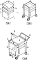
- FIGS. 7 to 9 show the construction of a concrete workshop trolley. This workshop trolley uses the frame configuration of FIG. 5.
- Fig. 7 first shows several storage containers 6 which are to be accommodated in the frame.
- a cabinet compartment 7 is provided as the lower storage container 6, which can be closed at the front with a door 8.
- Bores 9 are provided on the side walls of the cabinet compartment 7, with the aid of which the cabinet compartment can be screwed to the stand elements 2.
- a drawer compartment 10 is shown above the cabinet compartment 7, the side walls of which are also provided with bores 9.
- FIG. 8 An open compartment 11 is drawn above the drawer compartment 10, the side walls of which are in turn provided with bores 9.
- These three storage containers are now connected to the stand elements 2 of a frame, so that the configuration shown in FIG. 8 results.
- the connection is made, for example, by screwing it tight.
- a drawer is also inserted in the open compartment 11.
- Fig. 8 already shows a mobile composite tool trolley, which can now be expanded by further elements. It is of course also possible to fasten the storage containers 6 of FIG. 7 to the stand elements 2 in a different order.
- Fig. 9 shows the completed tool trolley. At the top, it is closed off by a worktop 12, which closes off the upper drawer compartment 11 and forms a stable work surface.
- the worktop 12 is connected as a single element to the stand elements 2, in particular screwed.
- the storage containers 6 shown in FIG. 7 are arranged in the space between the stand elements 2 and completely fill this space.
- the end faces of the tool trolley, which are still free in FIG. 8, are now occupied by additional elements 13, 14.
- the additional element 13 of FIG. 9 is designed as a complete element and has two handles 15 with which it can also be removed again.
- the additional element 13 contains an open compartment 16 in the lower region and a compartment closed by a door 17 in the upper region.
- the top of the additional element 13 is formed by a storage tray 18, which can have depressions so that objects can be placed there.
- a lamp 19 is attached to one stand element 2.
- An electrical connection can be provided in the tool trolley.
- the tool trolley On the opposite side, shown on the right in FIG. 9, the tool trolley is provided with a handle 20 which is designed in the form of a bow and is fastened to the stand elements 2 of the frame.
- the stability of the tool trolley is ensured by the frame itself, so that the individual storage boxes can be completed on their own and do not need to take on any key functions.
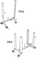
- FIG. 10 shows an embodiment of a frame with the basic configuration of FIG. 1.
- the parts forming the longitudinal and transverse beams and the stand elements 2 are designed as rectangular profiles. All rollers 5 are swivel rollers.
- Storage containers are in turn inserted into this frame and fastened with it, so that there is then an embodiment as shown in FIG. 11.
- a cabinet compartment 21 with a double door 22 is arranged.
- a drawer compartment 10 is inserted above this cabinet compartment.
- the cover 24 is designed such that it is aligned with the lateral storage surfaces 25 in the closed state. These storage surfaces are attached to the upper ends of the stand elements 2.
- the front edge on the left in FIG. 11 has a door flap 26, on the inside of which individual tools are fastened.
- a similar or other device can also be attached to the opposite end.
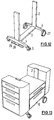
- FIG. 12 shows a frame similar to FIG. 10.
- the frame contains a side member 3 with two cross members 4.
- the stand elements 2 are arranged in the center of the cross members 4 and can, for example, also be in one piece with the cross members 4.
- Two non-pivotable wheels 27 are attached to one cross member 4, while two pivotable rollers 5 are arranged on the other cross member 4.
- a stand element 28, which can be lowered, is arranged on the underside of the front left cross member 4 in FIG. 12. It contains on its underside a plate 29 extending between the two swivel rollers 5 for resting on the floor.
- the stand element 28 can be lowered relative to the frame, so that it becomes possible to lock a workshop trolley provided with the frame of FIG. 12 in a stationary manner.
- FIG. 13 shows an example of a tool trolley provided with the frame of FIG. 12.
- several storage containers 6 are inserted into the space between the two stand elements 2, in this case with drawers. Additional elements are attached to the two end faces.
- a box with a circular saw arranged therein can be accommodated in the space remaining between the stand elements 2.
- the top of this plate would then be flush with the tops of the two additional elements. It is therefore also possible with the tool trolley according to the invention to accommodate boxes in which work machines are arranged.
- the frame is so stable that the tool trolley can even serve as a workbench.
- the lower frame element is formed by a longitudinal beam 3 and cross beams 4, which in turn are in two parts in the illustrated embodiment, so that they appear angled. Again, fixed or pivotable rollers 5 are provided.
- the longitudinal beams 3 and the cross beams 4 are constructed from profiles which are triangular in cross section, these profiles also being used for the upright elements 2 can find.
- a wide variety of accommodation boxes and tools can be attached.
Landscapes
- Engineering & Computer Science (AREA)
- Mechanical Engineering (AREA)
- Handcart (AREA)
- Yarns And Mechanical Finishing Of Yarns Or Ropes (AREA)
- Perforating, Stamping-Out Or Severing By Means Other Than Cutting (AREA)
- Workshop Equipment, Work Benches, Supports, Or Storage Means (AREA)
- Forklifts And Lifting Vehicles (AREA)
- Vending Machines For Individual Products (AREA)
Applications Claiming Priority (3)
| Application Number | Priority Date | Filing Date | Title |
|---|---|---|---|
| DE4324628 | 1993-07-22 | ||
| DE4324628A DE4324628A1 (de) | 1993-07-22 | 1993-07-22 | Vorrichtung zur Bereitstellung von Werkzeug und Material |
| US08/340,118 US5634649A (en) | 1993-07-22 | 1994-11-15 | Means for making ready tools and material |
Publications (2)
| Publication Number | Publication Date |
|---|---|
| EP0640447A1 true EP0640447A1 (fr) | 1995-03-01 |
| EP0640447B1 EP0640447B1 (fr) | 1998-08-19 |
Family
ID=25927920
Family Applications (1)
| Application Number | Title | Priority Date | Filing Date |
|---|---|---|---|
| EP94109182A Expired - Lifetime EP0640447B1 (fr) | 1993-07-22 | 1994-06-15 | Dispositif pour la mise à disposition d'outils et de matériels |
Country Status (9)
| Country | Link |
|---|---|
| US (1) | US5634649A (fr) |
| EP (1) | EP0640447B1 (fr) |
| JP (1) | JPH0788017A (fr) |
| AT (1) | ATE169852T1 (fr) |
| DE (2) | DE4324628A1 (fr) |
| DK (1) | DK0640447T3 (fr) |
| ES (1) | ES2122090T3 (fr) |
| FI (1) | FI943337A7 (fr) |
| NO (1) | NO301872B1 (fr) |
Cited By (6)
| Publication number | Priority date | Publication date | Assignee | Title |
|---|---|---|---|---|
| US6601930B2 (en) | 1998-02-02 | 2003-08-05 | 500 Group Inc. | Rolling containers assembly |
| CN102848366A (zh) * | 2012-09-17 | 2013-01-02 | 熙尔魄力科技(深圳)有限公司 | 多功能工具箱 |
| CN104440856A (zh) * | 2014-11-20 | 2015-03-25 | 国网河南鄢陵县供电公司 | 新型电力系统检修装置 |
| CN105922212A (zh) * | 2016-06-17 | 2016-09-07 | 无锡美羊动力科技有限公司 | 一种刀具盛放装置 |
| FR3122653A1 (fr) | 2021-05-04 | 2022-11-11 | Nestor Location | Ensemble de stockage modulable a dimensions ajustables |
| EP4470725A1 (fr) | 2023-05-30 | 2024-12-04 | Nestor Location | Ensemble de stockage modulable |
Families Citing this family (66)
| Publication number | Priority date | Publication date | Assignee | Title |
|---|---|---|---|---|
| DE19522679C1 (de) * | 1995-06-22 | 1996-08-14 | Daimler Benz Ag | Werkzeugwagen mit einer Leuchteneinrichtung |
| DE19624985A1 (de) * | 1996-06-22 | 1998-01-02 | Loh Kg Hailo Werk | Transportwagen |
| USD402133S (en) | 1996-08-27 | 1998-12-08 | Anderson Edward W | Portable storage tool cabinet |
| USD398727S (en) | 1997-03-27 | 1998-09-22 | Cambro Manufacturing Company | Meal delivery cart |
| IT1293879B1 (it) * | 1997-04-11 | 1999-03-11 | Iveco Fiat | Carrello di supporto di un'apparecchiatura elettronica di diagnostica di un veicolo industriale. |
| IL128303A (en) * | 1998-02-02 | 2002-02-10 | 500 Group Inc | Rolling containers assembly |
| SI9800062A (sl) | 1998-03-03 | 1999-10-31 | UNIOR Kovaška industrija d.d. | Mobilni zalogovnik za ročno orodje |
| US6092768A (en) * | 1998-06-29 | 2000-07-25 | Sioux Steam Cleaner Corporation | Rectangular support frame for supporting and transporting components of a cleaning device |
| DE19909830A1 (de) * | 1999-03-05 | 2000-09-07 | Wolfcraft Gmbh | Werktisch |
| US6733073B2 (en) * | 2001-03-02 | 2004-05-11 | Whiteside Mfg. Co. | Chair for a mechanic |
| DE20108642U1 (de) * | 2001-05-23 | 2001-08-09 | Durq Machinery Corp., Taichung | Kreissäge |
| AT414106B (de) * | 2002-09-17 | 2006-09-15 | Stoellinger Franz Ing | Fahrbarer, händisch schiebbarer und zusammenlegbarer untersatz für einen kistenförmigen behälter |
| US20040262867A1 (en) * | 2003-02-24 | 2004-12-30 | Rubbermaid Commercial Products Llc | Medical cart, medication module, height adjustment mechanism, and method of medication transport |
| US6945546B2 (en) | 2003-09-19 | 2005-09-20 | Guirlinger Edward G | Tool organizer |
| US20050077805A1 (en) * | 2003-10-10 | 2005-04-14 | Dalebout William T. | Modular storage cabinet |
| US7377525B1 (en) * | 2003-10-24 | 2008-05-27 | Andrew Whitmore | Portable worktable |
| US7963533B2 (en) * | 2003-11-17 | 2011-06-21 | Wenger Corporation | All-terrain retail merchandising unit |
| US7159726B1 (en) * | 2003-12-04 | 2007-01-09 | Stenton Paul A | Mobile merchandising unit |
| US7792763B2 (en) * | 2004-04-12 | 2010-09-07 | Ebay Inc. | Method and system to detect outlying behavior in a network-based marketplace |
| US7111852B2 (en) * | 2004-04-29 | 2006-09-26 | Kimball International, Inc. | Utility cart |
| WO2006001977A2 (fr) * | 2004-05-21 | 2006-01-05 | Milwaukee Electric Tool Corporation | Chariot industriel |
| US20060006621A1 (en) * | 2004-07-08 | 2006-01-12 | Santa Cruz Cathy D | Portable self-contained service cart arrangement |
| US7114733B2 (en) * | 2004-08-26 | 2006-10-03 | Ira Downs | Mobile work and supply station with crane eyelets and blueprint desk |
| US20060123712A1 (en) * | 2004-12-10 | 2006-06-15 | Vickie Nolting | Hair styling and beauty station and loading assembly |
| US20060284528A1 (en) * | 2005-04-29 | 2006-12-21 | Saunders Albert C | Mobile Workshop |
| USD530876S1 (en) * | 2005-10-14 | 2006-10-24 | Wyse Steven J | Drywall cart |
| US20080000171A1 (en) * | 2006-06-16 | 2008-01-03 | Bradyquin, Llc | Portable workstation |
| US8322732B2 (en) * | 2006-06-16 | 2012-12-04 | Bradyquin, Llc | Portable workstation |
| US20090058245A1 (en) * | 2007-09-05 | 2009-03-05 | He Yue Fang | Mobile appliance |
| US20090243243A1 (en) * | 2008-03-26 | 2009-10-01 | Watson Brad A | E.E.Z.Z.CAR care garage caddy |
| US8191910B2 (en) * | 2008-04-15 | 2012-06-05 | The Stanley Works Israel Ltd. | Containers and container system |
| US7883096B2 (en) * | 2008-05-22 | 2011-02-08 | The Stanley Works Israel Ltd. | Tool container assembly with sliding door |
| US7789403B2 (en) * | 2008-05-27 | 2010-09-07 | Sleeka Vi Int'l, Llc | Vanity cart with mirror |
| US8162330B2 (en) * | 2008-07-31 | 2012-04-24 | Ashot Melkumyan | Multi-purpose mobile cart |
| US8132819B2 (en) * | 2009-05-15 | 2012-03-13 | The Stanley Works Israel Ltd. | Rolling container assembly with mount structure |
| US8157337B2 (en) * | 2009-06-16 | 2012-04-17 | Edwin Dizon Manalang | Tool box storage assembly |
| US20110043085A1 (en) * | 2009-08-21 | 2011-02-24 | SherpaMax LLC | Portable container and workstation |
| US9132543B2 (en) | 2009-09-01 | 2015-09-15 | The Stanley Works Israel Ltd. | Rolling container assembly with adjustable storage units |
| US8567796B2 (en) | 2009-09-01 | 2013-10-29 | The Stanley Works Israel Ltd. | Rolling container assembly with adjustable storage units |
| USRE47022E1 (en) | 2009-12-11 | 2018-09-04 | The Stanley Works Israel Ltd. | Container |
| US8360446B1 (en) * | 2011-07-22 | 2013-01-29 | Hertan Bernard A | Wheeled firearms transport case |
| US8668209B1 (en) * | 2011-08-18 | 2014-03-11 | Mary Sue Anzivino | Portable modular tool cabinet systems |
| US9463069B2 (en) * | 2012-10-23 | 2016-10-11 | Spinesmith Partners, L.P. | Automated work station for point-of-care cell and biological fluid processing |
| US9050718B2 (en) | 2013-02-05 | 2015-06-09 | Jpl Investments, Llc | Securable and collapsible work station |
| US20140265440A1 (en) * | 2013-03-14 | 2014-09-18 | Kung-Cheng Chen | Cart having corner bumpers, side containers, and corner top holders |
| DE102013113238A1 (de) * | 2013-11-29 | 2015-06-03 | Ralf Honeck | Leuchtenvorrichtung für eine Fahrzeug-Hebebühne |
| US8944444B1 (en) * | 2013-12-23 | 2015-02-03 | Patrick G. Tvrdy | Vertical tool box |
| CN103909512A (zh) * | 2014-03-31 | 2014-07-09 | 江苏南车电机有限公司 | 一种大型永磁风力发电机装配用紧固件运输工装 |
| US10575417B2 (en) | 2014-09-08 | 2020-02-25 | The Stanley Works Israel Ltd. | Jobsite communications center |
| CN105033515A (zh) * | 2015-07-14 | 2015-11-11 | 浙江新工机械制造有限公司 | 一种用于放置焊接工件的推车机构 |
| US10350748B2 (en) | 2016-02-12 | 2019-07-16 | Matco Tools Corporation | Tool storage unit having a moveable housing |
| US9527205B1 (en) * | 2016-05-02 | 2016-12-27 | Yun-Huei Lin | Cart for storage of tools and parts |
| US10246116B2 (en) * | 2016-10-25 | 2019-04-02 | Rubbermaid Commercial Products Llc | Multipurpose utility carts |
| CN107053106A (zh) * | 2017-03-21 | 2017-08-18 | 南宁市黑晶信息技术有限公司 | 一种方便高效的千分尺放置台 |
| USD849461S1 (en) * | 2017-08-14 | 2019-05-28 | Gary Moffat | Low profile workbench |
| USD841375S1 (en) * | 2017-10-26 | 2019-02-26 | Gary Moffat | Dual height workbench |
| AU201716528S (en) * | 2017-10-27 | 2017-11-15 | Comfortel Furniture Pty Ltd | Trolley |
| JP2019099136A (ja) * | 2017-11-28 | 2019-06-24 | 有限会社仁木ガラス | 交換する自動車ガラスの取り付けに使用される作業台とこの作業台を使用する自動車ガラスの取り付け方法 |
| CN108890604A (zh) * | 2018-08-28 | 2018-11-27 | 上海麦源实业有限公司 | 一种具有多侧抽屉的工具车 |
| WO2021087422A1 (fr) | 2019-11-01 | 2021-05-06 | Tvrdy 8, Llc | Système de rangement par étage horizontal d'outils et accessoires de rangement par étage d'outils comportant une enceinte sécurisée et ayant des capacités de positionnement d'outils |
| US11647835B2 (en) | 2020-03-30 | 2023-05-16 | Smith System Manufacturing Company | Storage assembly |
| EP4244118A4 (fr) | 2020-11-10 | 2024-11-20 | Milwaukee Electric Tool Corporation | Dispositif de stockage et de transport mobile |
| CN113199447A (zh) * | 2021-05-12 | 2021-08-03 | 郑州铁路职业技术学院 | 一种轨道交通地铁车辆检修用工具箱 |
| USD1000031S1 (en) * | 2021-09-28 | 2023-09-26 | TNT Sports Equipment | Shoulder pad storage cart |
| DE102022201164A1 (de) * | 2022-02-03 | 2023-08-03 | Festool Gmbh | Transportbox, Stapelanordnung, Transportanordnung, Kraftfahrzeug und Verfahren |
| CN223791504U (zh) | 2022-07-26 | 2026-01-13 | 米沃奇电动工具公司 | 移动支承装置 |
Citations (6)
| Publication number | Priority date | Publication date | Assignee | Title |
|---|---|---|---|---|
| FR927776A (fr) * | 1946-06-11 | 1947-11-10 | Chariot pour transport de boîtes à outils et d'accessoires divers dans les garages et autres | |
| EP0053649A1 (fr) * | 1980-12-05 | 1982-06-16 | Hazet-Werk Hermann Zerver GmbH & Co. KG | Récipient mobile |
| FR2575957A1 (fr) * | 1985-01-16 | 1986-07-18 | Hamon Richard | Servante d'atelier verticale comprenant un etau ou etabli et plan de travail |
| DE3510307A1 (de) * | 1985-03-22 | 1986-09-25 | KH Wärme & Service AG, Luzern | Vorrichtung zur durchfuehrung von service-leistungen |
| US5013055A (en) * | 1989-10-23 | 1991-05-07 | Labrum Randall C | Tool caddy with self-contained power |
| US5048857A (en) * | 1989-10-26 | 1991-09-17 | Colgate-Palmolive Company | Vertically collapsible food service cart system |
Family Cites Families (18)
| Publication number | Priority date | Publication date | Assignee | Title |
|---|---|---|---|---|
| DE1724796U (de) * | 1956-04-06 | 1956-06-21 | Wilhelm Baecker Werkzeugfabrik | Fahrbarer werktisch fuer kraftfahrzeug werkstaetten usw. |
| US3148923A (en) * | 1961-12-06 | 1964-09-15 | Glenn L Smith | Portable combined tool kit and work bench |
| DE2204595A1 (de) * | 1972-02-01 | 1973-08-09 | Horst Muench | Maschinenwagen zur befestigung von kleinmaschinen |
| US3879053A (en) * | 1973-06-27 | 1975-04-22 | Coca Cola Co | Mobile display cart |
| US4070075A (en) * | 1975-10-23 | 1978-01-24 | Morgan Robin H | Ammunition loading bench |
| FR2330508A1 (fr) * | 1975-11-05 | 1977-06-03 | Albert Heinrich | Caisse a outils mobile faisant office d'etabli |
| US4512591A (en) * | 1982-07-06 | 1985-04-23 | Plante Jean Paul | Hand truck |
| DE8219280U1 (de) * | 1982-07-06 | 1982-11-18 | Wagner, Hans-Joachim, 5630 Remscheid | Bereitstellungsgeraet fuer mehrere handwerkzeuge, kleininstrumente oder dergleichen teile |
| US4641845A (en) * | 1985-01-24 | 1987-02-10 | Hewitt Timothy W | Wheeled pallet |
| DE8601410U1 (de) * | 1986-01-21 | 1986-03-06 | Albert Berner GmbH & Co KG, 7118 Künzelsau | Werkstattwagen |
| US4733703A (en) * | 1986-04-16 | 1988-03-29 | Cimino Eugene D | Combination tool chest/workbench |
| NL8702845A (nl) * | 1987-11-26 | 1989-06-16 | Anne Hoekstra En Ate Ide Maria | Verrijdbare gereedschapskar. |
| US4976450A (en) * | 1988-02-10 | 1990-12-11 | Ellefson Laurence M | Mobile tool chest with horizontal pivotal trays |
| DE8808848U1 (de) * | 1988-07-09 | 1988-08-25 | ELORA-Werkzeugfabrik GmbH, 5630 Remscheid | Werkzeugbehältnis |
| DE3918162C1 (fr) * | 1989-06-03 | 1990-10-31 | Riwoplan Medizin-Technische Einrichtungsgesellschaft Mbh, 7134 Knittlingen, De | |
| DE9001756U1 (de) * | 1990-02-15 | 1990-04-19 | Adolf Würth GmbH & Co KG, 7118 Künzelsau | Werkzeugwagen |
| US5190302A (en) * | 1990-05-03 | 1993-03-02 | Electronic Voting Systems, Inc. | Transportable component stand |
| US5280933A (en) * | 1992-07-27 | 1994-01-25 | Finneyfrock David N | Tip over resistant, debris retaining omni directionally mobilized rack for wood logs |
-
1993
- 1993-07-22 DE DE4324628A patent/DE4324628A1/de not_active Withdrawn
-
1994
- 1994-06-15 ES ES94109182T patent/ES2122090T3/es not_active Expired - Lifetime
- 1994-06-15 DK DK94109182T patent/DK0640447T3/da active
- 1994-06-15 DE DE59406721T patent/DE59406721D1/de not_active Expired - Lifetime
- 1994-06-15 EP EP94109182A patent/EP0640447B1/fr not_active Expired - Lifetime
- 1994-06-15 AT AT94109182T patent/ATE169852T1/de not_active IP Right Cessation
- 1994-07-11 JP JP6180425A patent/JPH0788017A/ja active Pending
- 1994-07-13 FI FI943337A patent/FI943337A7/fi unknown
- 1994-07-18 NO NO942693A patent/NO301872B1/no not_active IP Right Cessation
- 1994-11-15 US US08/340,118 patent/US5634649A/en not_active Expired - Fee Related
Patent Citations (6)
| Publication number | Priority date | Publication date | Assignee | Title |
|---|---|---|---|---|
| FR927776A (fr) * | 1946-06-11 | 1947-11-10 | Chariot pour transport de boîtes à outils et d'accessoires divers dans les garages et autres | |
| EP0053649A1 (fr) * | 1980-12-05 | 1982-06-16 | Hazet-Werk Hermann Zerver GmbH & Co. KG | Récipient mobile |
| FR2575957A1 (fr) * | 1985-01-16 | 1986-07-18 | Hamon Richard | Servante d'atelier verticale comprenant un etau ou etabli et plan de travail |
| DE3510307A1 (de) * | 1985-03-22 | 1986-09-25 | KH Wärme & Service AG, Luzern | Vorrichtung zur durchfuehrung von service-leistungen |
| US5013055A (en) * | 1989-10-23 | 1991-05-07 | Labrum Randall C | Tool caddy with self-contained power |
| US5048857A (en) * | 1989-10-26 | 1991-09-17 | Colgate-Palmolive Company | Vertically collapsible food service cart system |
Cited By (9)
| Publication number | Priority date | Publication date | Assignee | Title |
|---|---|---|---|---|
| US6601930B2 (en) | 1998-02-02 | 2003-08-05 | 500 Group Inc. | Rolling containers assembly |
| CN102848366A (zh) * | 2012-09-17 | 2013-01-02 | 熙尔魄力科技(深圳)有限公司 | 多功能工具箱 |
| CN102848366B (zh) * | 2012-09-17 | 2014-12-31 | 熙尔魄力科技(深圳)有限公司 | 多功能工具箱 |
| CN104440856A (zh) * | 2014-11-20 | 2015-03-25 | 国网河南鄢陵县供电公司 | 新型电力系统检修装置 |
| CN105922212A (zh) * | 2016-06-17 | 2016-09-07 | 无锡美羊动力科技有限公司 | 一种刀具盛放装置 |
| FR3122653A1 (fr) | 2021-05-04 | 2022-11-11 | Nestor Location | Ensemble de stockage modulable a dimensions ajustables |
| BE1029315A1 (fr) | 2021-05-04 | 2022-11-14 | Nestor Location | Ensemble de stockage modulable a dimensions ajustables |
| EP4470725A1 (fr) | 2023-05-30 | 2024-12-04 | Nestor Location | Ensemble de stockage modulable |
| FR3149174A1 (fr) | 2023-05-30 | 2024-12-06 | Nestor Location | Ensemble de stockage modulable |
Also Published As
| Publication number | Publication date |
|---|---|
| FI943337L (fi) | 1995-01-23 |
| DE59406721D1 (de) | 1998-09-24 |
| US5634649A (en) | 1997-06-03 |
| FI943337A7 (fi) | 1995-01-23 |
| DE4324628A1 (de) | 1995-01-26 |
| NO942693L (no) | 1995-01-23 |
| NO942693D0 (no) | 1994-07-18 |
| NO301872B1 (no) | 1997-12-22 |
| FI943337A0 (fi) | 1994-07-13 |
| DK0640447T3 (da) | 1999-05-25 |
| JPH0788017A (ja) | 1995-04-04 |
| ATE169852T1 (de) | 1998-09-15 |
| ES2122090T3 (es) | 1998-12-16 |
| EP0640447B1 (fr) | 1998-08-19 |
Similar Documents
| Publication | Publication Date | Title |
|---|---|---|
| EP0640447B1 (fr) | Dispositif pour la mise à disposition d'outils et de matériels | |
| DE2800575C2 (de) | Stapelbarer Transportwagen | |
| EP0319969B1 (fr) | Dispositif de stockage des outils, des pièces de travail et des petites choses, particulièrement pour le travail sur les automobiles | |
| DE3640407A1 (de) | Handkarren mit tankhalter | |
| EP0811542B1 (fr) | Dispositif de réception pour toit amovible | |
| EP1772389B1 (fr) | Support pour charges de grandes dimensions | |
| EP2424762B1 (fr) | Dispositif de transport d'équipements de scène | |
| DE603548C (de) | Behaelter | |
| EP0442374B1 (fr) | Chariot porte-outils | |
| DE3128137C2 (de) | Arbeitstisch, insbesondere Bürotisch | |
| DE202011050718U1 (de) | Werkstattwagen | |
| EP0824998A1 (fr) | Outil pour la manutention d'une machine-outil | |
| DE102019102117B4 (de) | Transportwagen insbesondere zum Ablegen und Transportieren von Gegenständen wie Werkzeugen und/oder Werkstücken | |
| DE10307394A1 (de) | Transportwagensystem zum manuellen Ein-, Um- und Auslagern | |
| DE3519960A1 (de) | Transport-handwagen | |
| EP0855330A1 (fr) | Dispositif de basculement et de transport pour un piano à queue | |
| DE3505500A1 (de) | Vorrichtung mit stapelplatten zur etagenweisen aufnahme von einem roboter darzubietenden werkstuecken | |
| DE69306704T2 (de) | Lagereinrichtung mit fahrbaren Tragelementen | |
| DE60317181T2 (de) | Maschinenkonstruktion, insbesondere zur handhabung von fluidprodukten und verfahren zu ihrer montage | |
| EP0737609A2 (fr) | Chariot pour panneaux | |
| DE29807838U1 (de) | Tragbare Werkbank mit einem Werkzeugkasten | |
| DE10162007B4 (de) | Handbetätigter Transportwagen | |
| EP0235313B1 (fr) | Dispositif pour lever ou déposer des grands récipients transportables, par exemple des cabines, des containers ou similaires | |
| DE19845738A1 (de) | Rollgestell | |
| DE20003357U1 (de) | Werkzeugwagen |
Legal Events
| Date | Code | Title | Description |
|---|---|---|---|
| PUAI | Public reference made under article 153(3) epc to a published international application that has entered the european phase |
Free format text: ORIGINAL CODE: 0009012 |
|
| AK | Designated contracting states |
Kind code of ref document: A1 Designated state(s): AT BE CH DE DK ES FR GB GR IE IT LI NL SE |
|
| 17P | Request for examination filed |
Effective date: 19950628 |
|
| 17Q | First examination report despatched |
Effective date: 19961223 |
|
| GRAG | Despatch of communication of intention to grant |
Free format text: ORIGINAL CODE: EPIDOS AGRA |
|
| GRAG | Despatch of communication of intention to grant |
Free format text: ORIGINAL CODE: EPIDOS AGRA |
|
| GRAH | Despatch of communication of intention to grant a patent |
Free format text: ORIGINAL CODE: EPIDOS IGRA |
|
| GRAH | Despatch of communication of intention to grant a patent |
Free format text: ORIGINAL CODE: EPIDOS IGRA |
|
| GRAA | (expected) grant |
Free format text: ORIGINAL CODE: 0009210 |
|
| AK | Designated contracting states |
Kind code of ref document: B1 Designated state(s): AT BE CH DE DK ES FR GB GR IE IT LI NL SE |
|
| REF | Corresponds to: |
Ref document number: 169852 Country of ref document: AT Date of ref document: 19980915 Kind code of ref document: T |
|
| REG | Reference to a national code |
Ref country code: CH Ref legal event code: NV Representative=s name: TROESCH SCHEIDEGGER WERNER AG Ref country code: CH Ref legal event code: EP |
|
| REF | Corresponds to: |
Ref document number: 59406721 Country of ref document: DE Date of ref document: 19980924 |
|
| ET | Fr: translation filed | ||
| REG | Reference to a national code |
Ref country code: IE Ref legal event code: FG4D Free format text: GERMAN |
|
| GBT | Gb: translation of ep patent filed (gb section 77(6)(a)/1977) |
Effective date: 19981110 |
|
| REG | Reference to a national code |
Ref country code: ES Ref legal event code: FG2A Ref document number: 2122090 Country of ref document: ES Kind code of ref document: T3 |
|
| REG | Reference to a national code |
Ref country code: DK Ref legal event code: T3 |
|
| PLBE | No opposition filed within time limit |
Free format text: ORIGINAL CODE: 0009261 |
|
| STAA | Information on the status of an ep patent application or granted ep patent |
Free format text: STATUS: NO OPPOSITION FILED WITHIN TIME LIMIT |
|
| 26N | No opposition filed | ||
| PGFP | Annual fee paid to national office [announced via postgrant information from national office to epo] |
Ref country code: GB Payment date: 20010605 Year of fee payment: 8 |
|
| PGFP | Annual fee paid to national office [announced via postgrant information from national office to epo] |
Ref country code: IE Payment date: 20010620 Year of fee payment: 8 |
|
| PGFP | Annual fee paid to national office [announced via postgrant information from national office to epo] |
Ref country code: GR Payment date: 20010627 Year of fee payment: 8 |
|
| REG | Reference to a national code |
Ref country code: GB Ref legal event code: IF02 |
|
| PG25 | Lapsed in a contracting state [announced via postgrant information from national office to epo] |
Ref country code: GB Free format text: LAPSE BECAUSE OF NON-PAYMENT OF DUE FEES Effective date: 20020615 |
|
| PG25 | Lapsed in a contracting state [announced via postgrant information from national office to epo] |
Ref country code: IE Free format text: LAPSE BECAUSE OF NON-PAYMENT OF DUE FEES Effective date: 20020617 |
|
| PG25 | Lapsed in a contracting state [announced via postgrant information from national office to epo] |
Ref country code: GR Free format text: LAPSE BECAUSE OF NON-PAYMENT OF DUE FEES Effective date: 20021231 |
|
| GBPC | Gb: european patent ceased through non-payment of renewal fee |
Effective date: 20020615 |
|
| REG | Reference to a national code |
Ref country code: IE Ref legal event code: MM4A |
|
| PGFP | Annual fee paid to national office [announced via postgrant information from national office to epo] |
Ref country code: AT Payment date: 20040611 Year of fee payment: 11 |
|
| PGFP | Annual fee paid to national office [announced via postgrant information from national office to epo] |
Ref country code: NL Payment date: 20040617 Year of fee payment: 11 |
|
| PGFP | Annual fee paid to national office [announced via postgrant information from national office to epo] |
Ref country code: DK Payment date: 20040622 Year of fee payment: 11 |
|
| PGFP | Annual fee paid to national office [announced via postgrant information from national office to epo] |
Ref country code: SE Payment date: 20040623 Year of fee payment: 11 Ref country code: CH Payment date: 20040623 Year of fee payment: 11 Ref country code: BE Payment date: 20040623 Year of fee payment: 11 |
|
| PG25 | Lapsed in a contracting state [announced via postgrant information from national office to epo] |
Ref country code: AT Free format text: LAPSE BECAUSE OF NON-PAYMENT OF DUE FEES Effective date: 20050615 |
|
| PG25 | Lapsed in a contracting state [announced via postgrant information from national office to epo] |
Ref country code: SE Free format text: LAPSE BECAUSE OF NON-PAYMENT OF DUE FEES Effective date: 20050616 |
|
| PG25 | Lapsed in a contracting state [announced via postgrant information from national office to epo] |
Ref country code: LI Free format text: LAPSE BECAUSE OF NON-PAYMENT OF DUE FEES Effective date: 20050630 Ref country code: DK Free format text: LAPSE BECAUSE OF NON-PAYMENT OF DUE FEES Effective date: 20050630 Ref country code: CH Free format text: LAPSE BECAUSE OF NON-PAYMENT OF DUE FEES Effective date: 20050630 Ref country code: BE Free format text: LAPSE BECAUSE OF NON-PAYMENT OF DUE FEES Effective date: 20050630 |
|
| PG25 | Lapsed in a contracting state [announced via postgrant information from national office to epo] |
Ref country code: NL Free format text: LAPSE BECAUSE OF NON-PAYMENT OF DUE FEES Effective date: 20060101 |
|
| REG | Reference to a national code |
Ref country code: CH Ref legal event code: PL |
|
| EUG | Se: european patent has lapsed | ||
| NLV4 | Nl: lapsed or anulled due to non-payment of the annual fee |
Effective date: 20060101 |
|
| REG | Reference to a national code |
Ref country code: DK Ref legal event code: EBP |
|
| BERE | Be: lapsed |
Owner name: ADOLF *WURTH G.M.B.H. & CO. K.G. Effective date: 20050630 |
|
| PGFP | Annual fee paid to national office [announced via postgrant information from national office to epo] |
Ref country code: ES Payment date: 20090624 Year of fee payment: 16 |
|
| PGFP | Annual fee paid to national office [announced via postgrant information from national office to epo] |
Ref country code: IT Payment date: 20090623 Year of fee payment: 16 Ref country code: FR Payment date: 20090615 Year of fee payment: 16 |
|
| REG | Reference to a national code |
Ref country code: FR Ref legal event code: ST Effective date: 20110228 |
|
| PG25 | Lapsed in a contracting state [announced via postgrant information from national office to epo] |
Ref country code: IT Free format text: LAPSE BECAUSE OF NON-PAYMENT OF DUE FEES Effective date: 20100615 |
|
| PG25 | Lapsed in a contracting state [announced via postgrant information from national office to epo] |
Ref country code: FR Free format text: LAPSE BECAUSE OF NON-PAYMENT OF DUE FEES Effective date: 20100630 |
|
| REG | Reference to a national code |
Ref country code: ES Ref legal event code: FD2A Effective date: 20110715 |
|
| PG25 | Lapsed in a contracting state [announced via postgrant information from national office to epo] |
Ref country code: ES Free format text: LAPSE BECAUSE OF NON-PAYMENT OF DUE FEES Effective date: 20110705 |
|
| PG25 | Lapsed in a contracting state [announced via postgrant information from national office to epo] |
Ref country code: ES Free format text: LAPSE BECAUSE OF NON-PAYMENT OF DUE FEES Effective date: 20100616 |
|
| PGFP | Annual fee paid to national office [announced via postgrant information from national office to epo] |
Ref country code: DE Payment date: 20120622 Year of fee payment: 19 |
|
| REG | Reference to a national code |
Ref country code: DE Ref legal event code: R119 Ref document number: 59406721 Country of ref document: DE Effective date: 20140101 |
|
| PG25 | Lapsed in a contracting state [announced via postgrant information from national office to epo] |
Ref country code: DE Free format text: LAPSE BECAUSE OF NON-PAYMENT OF DUE FEES Effective date: 20140101 |