EP0640529B1 - Dispositif pour banderoler des produits d'imprimerie - Google Patents
Dispositif pour banderoler des produits d'imprimerie Download PDFInfo
- Publication number
- EP0640529B1 EP0640529B1 EP94110563A EP94110563A EP0640529B1 EP 0640529 B1 EP0640529 B1 EP 0640529B1 EP 94110563 A EP94110563 A EP 94110563A EP 94110563 A EP94110563 A EP 94110563A EP 0640529 B1 EP0640529 B1 EP 0640529B1
- Authority
- EP
- European Patent Office
- Prior art keywords
- stack
- pressing
- pressing apparatus
- floor
- partial
- Prior art date
- Legal status (The legal status is an assumption and is not a legal conclusion. Google has not performed a legal analysis and makes no representation as to the accuracy of the status listed.)
- Expired - Lifetime
Links
- 230000036961 partial effect Effects 0.000 claims description 45
- 238000003466 welding Methods 0.000 claims description 25
- 238000000034 method Methods 0.000 claims description 13
- 230000008569 process Effects 0.000 claims description 13
- 230000000284 resting effect Effects 0.000 claims description 4
- 230000008901 benefit Effects 0.000 description 5
- 230000000670 limiting effect Effects 0.000 description 5
- 230000008921 facial expression Effects 0.000 description 4
- 238000010276 construction Methods 0.000 description 3
- 230000009467 reduction Effects 0.000 description 2
- 230000002829 reductive effect Effects 0.000 description 2
- 230000000717 retained effect Effects 0.000 description 2
- 238000007665 sagging Methods 0.000 description 2
- 238000011144 upstream manufacturing Methods 0.000 description 2
- 230000004888 barrier function Effects 0.000 description 1
- 230000000903 blocking effect Effects 0.000 description 1
- 230000006835 compression Effects 0.000 description 1
- 238000007906 compression Methods 0.000 description 1
- 230000001419 dependent effect Effects 0.000 description 1
- 230000007717 exclusion Effects 0.000 description 1
- 230000002349 favourable effect Effects 0.000 description 1
- 230000001771 impaired effect Effects 0.000 description 1
- 238000007689 inspection Methods 0.000 description 1
- 238000009434 installation Methods 0.000 description 1
- 230000007257 malfunction Effects 0.000 description 1
- 238000004806 packaging method and process Methods 0.000 description 1
- 238000012536 packaging technology Methods 0.000 description 1
- 238000007639 printing Methods 0.000 description 1
- 230000001360 synchronised effect Effects 0.000 description 1
- 230000007704 transition Effects 0.000 description 1
Images


Classifications
-
- B—PERFORMING OPERATIONS; TRANSPORTING
- B65—CONVEYING; PACKING; STORING; HANDLING THIN OR FILAMENTARY MATERIAL
- B65B—MACHINES, APPARATUS OR DEVICES FOR, OR METHODS OF, PACKAGING ARTICLES OR MATERIALS; UNPACKING
- B65B63/00—Auxiliary devices, not otherwise provided for, for operating on articles or materials to be packaged
- B65B63/02—Auxiliary devices, not otherwise provided for, for operating on articles or materials to be packaged for compressing or compacting articles or materials prior to wrapping or insertion in containers or receptacles
-
- B—PERFORMING OPERATIONS; TRANSPORTING
- B65—CONVEYING; PACKING; STORING; HANDLING THIN OR FILAMENTARY MATERIAL
- B65B—MACHINES, APPARATUS OR DEVICES FOR, OR METHODS OF, PACKAGING ARTICLES OR MATERIALS; UNPACKING
- B65B13/00—Bundling articles
- B65B13/18—Details of, or auxiliary devices used in, bundling machines or bundling tools
- B65B13/20—Means for compressing or compacting bundles prior to bundling
-
- B—PERFORMING OPERATIONS; TRANSPORTING
- B65—CONVEYING; PACKING; STORING; HANDLING THIN OR FILAMENTARY MATERIAL
- B65B—MACHINES, APPARATUS OR DEVICES FOR, OR METHODS OF, PACKAGING ARTICLES OR MATERIALS; UNPACKING
- B65B27/00—Bundling particular articles presenting special problems using string, wire, or narrow tape or band; Baling fibrous material, e.g. peat, not otherwise provided for
- B65B27/08—Bundling paper sheets, envelopes, bags, newspapers, or other thin flat articles
-
- B—PERFORMING OPERATIONS; TRANSPORTING
- B65—CONVEYING; PACKING; STORING; HANDLING THIN OR FILAMENTARY MATERIAL
- B65H—HANDLING THIN OR FILAMENTARY MATERIAL, e.g. SHEETS, WEBS, CABLES
- B65H2301/00—Handling processes for sheets or webs
- B65H2301/40—Type of handling process
- B65H2301/42—Piling, depiling, handling piles
- B65H2301/422—Handling piles, sets or stacks of articles
- B65H2301/4223—Pressing piles
Definitions
- the invention relates to a device for banding copies of printed products according to the preamble of claim 1, with a stacking device in which the copies are stacked into a stack on a vertically up and down movable floor, with a pressing device that can be brought over the stack formed the underside of which the upper end of the stack formed can be pressed to compress the stack, and with a banding device for circumferentially enclosing the stack with a band.
- Such a device is known from DE 37 42 787 C2.
- the copies of printed products for example brochure sheets or the like, are fed from a preceding station to the stacking device, this usually being done via conveyor belts.
- the individual specimens are piled up in a stack on a floor that can be moved up and down vertically.
- angular strips arranged around the floor or lateral guides for example baffle plates or the like, are provided.
- the floor is gradually lowered in accordance with the increase in the height of the stack, so that the specimens placed or falling into the ground each have approximately the same fall height, whereby a uniform stack is gradually formed.
- a pressing device is brought over the stack.
- the pressing device in the above-mentioned device consists, for example, of laterally retractable pressing bars, on the underside of which the top of the stack is pressed in that the bottom, together with the stack accommodated therein, is moved from below to the pressing bar and is thereby pressed together.
- This pressing together is necessary because the specimens falling individually into the stacking device are piled up quite loosely, so that when a band is placed around such a loose stack there would be difficulties in banding or there is a risk that specimens would subsequently fall out of the banded loose stack .
- a band is then placed around the stack of specimens pressed in between the base on the one hand and the press beam on the other hand, and the band is welded by means of welding punches and thereby separated from the remaining band.
- the bottom is then lowered and the banded stack is removed.
- a disadvantage of such a device is that two floors must be provided with the appropriate movement facial expressions, so that the device is quite complex, and also builds very high in the vertical direction, since at the time when the pressing and banding processes on the actual floor take place in the same chute the partial stack floor must be able to accommodate the copies fed from the conveyor belts unchanged in the feed level.
- the stacking devices arranged one above the other are difficult to reach in the event of a malfunction or for inspection purposes.
- Another problem is that the part stack stacked on the bottom of the partial stacking device must be transferred to the actual bottom of the stacking arrangement arranged underneath, which is done in the device mentioned at the outset in that the partial stack bottom is formed in two parts and the two part halves are subtracted when transferring be, whereby the entire partial stack falls vertically down on the actual stack floor over a considerable distance. Due to the free fall distance, individual copies can detach from the partial stack and get tangled, so that unsightly stacks are formed which are also difficult to band afterwards.
- the object is achieved in a device according to the preamble of claim 1 in that an upper side of the pressing device is designed as a further base on which a partial stack of copies is stacked during the pressing and banding process, and in that the partial stack is opened by the pressing device the floor can be raised and lowered.
- the pressing device now has a double function, i.e. the underside of which serves that the stack picked up on the bottom of the stacking device is brought up for compression, but at the same time on the top of the pressing device, since this is now designed as a bottom, the partial stack can be built up.
- the floor can be raised and lowered in such a way that it can be moved vertically into the pressing device, thereby lifting the partial stack resting on the top of the pressing device, after which the pressing device comes out of the vertical movement shaft of the floor that can be raised and lowered is feasible.
- the pressing device has pressing bars which can be moved laterally onto the stack, and the lowerable floor can be moved vertically between the pressing bars in order to lift the partial stack.
- welding punches of the banding device can be brought over the stack in the same direction as the pressing device.
- This measure now has the advantage that the facial expressions and control can be synchronized with the pressing device or its retracting and extending movements, which enables a further reduction of the components, in particular no additional components in the vertical direction are necessary.
- the welding punches are arranged between two outer press bars, and the overall height of the welding punches is such that they extend vertically between the top and the bottom of the pressing device.
- This measure has the considerable advantage that the welding punches have a space immediately above the uppermost copy of the pressed punch, which ends at the bottom of the pressing device and below the lower copy of the partial stack arranged above it. This ensures that the banderole is guided and welded directly above the top copy of the lower pressed stack can, however, at the same time in no way be impaired by the movement of the welding stamp in the horizontal direction of the stack formed in the meantime on the upper side of the pressing device or its lowest copies.
- the top of the pressing device is designed as a roller base, and the pressing device can be pulled off to the side, the bottom of the stacking device being liftable approximately at the same level as the roller base, and that when the pressing device is pulled off the side, the partial stack formed thereon can be retained and onto the floor the stacking device can be stored.
- FIG. 1 A device according to the invention shown in FIG. 1 is provided with the reference number 10 in its entirety.
- the device 10 has a stacking device 12, a pressing device 14 and a banding device 16.
- the stacking device 12 is assigned a conveyor belt 18 as well as a conveyor roller 20 and a further conveyor belt 22 in order to feed copies of printed products, for example brochures or folded sheets and the like, from an upstream station.
- the combination of the two conveyor belts 18 and 22 in cooperation with the transport roller 20 serves for synchronization and controlled feeding of the specimens to be stacked in the stacking device 12.
- An foremost end edge 24 of the conveyor belt 22 in the transport direction lies along a side edge of a shaft 26 which is approximately rectangular in cross section, the contour of which roughly corresponds to the contour of the specimens to be stacked.
- a pivotable lock 28 is arranged, which can be lowered from the releasing position shown in FIG. 1 to the top of the conveyor belt 22, in order to continue transporting copies there at short notice while the conveyor belt 22 is still running to block, as will be explained below in connection with the operation of the device 10.
- the stacking device 12 has a base 30 which can be moved up and down vertically in the shaft 26 by means of facial expressions, not shown here, as is indicated in FIG. 1 by an arrow 31.
- the facial expressions for moving the floor 30 are in themselves Known in the field of packaging technology, therefore does not need to be described in more detail, for example by vertical chain guides, vertically extendable stamps or the like.
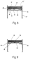
- the shaft 26, seen in the transport direction of the conveyor belts 18 and 22, is provided with a rear limiting rail 32, a front limiting rail 34, and two lateral limiting rails 36 and 37 (see also FIGS. 8 and 9), which thus cover the floor 30 on all of them surround four sides, and serve for lateral guidance of specimens stacked on the floor 30, as is also known per se in this field.
- the pressing device 14 has two pressing bars 38 and 39 arranged laterally next to the shaft 26 (see also FIGS. 8 and 9), which are driven by a drive (not shown here) from the position shown in FIG. 1, in which it is next to the shaft 26 are arranged, horizontally, in the representation of FIG. 1 to the left in the shaft 26 can be moved in or out again, as indicated by a double arrow 41.
- the pressure beams 38, 39 can also be driven again by suitable means known per se in this field, such as chain guides, piston-cylinder units or the like.
- the press bars 38 and 39 are each provided with the same lower sides 40 and the same upper sides 42.
- the banding device 16 has a roll 48, which is pivotably received on a lever arm 46 and on which a band 49 is rolled up.
- the banderole 49 leading away from the roll 48 is guided over guide rollers 50 and 51, between which the banderole 49 sags, over a welding stamp 58 and over the top of the bottom 30 through the shaft 26, then runs around a further guide roller 52 and a guide roller 53 on the opposite side.
- the banderole 49 is guided from the guide roller 53 to a further guide roller 54, the banderole 49 also sagging between these two approximately equal guide rollers 53 and 54 for compensation purposes.
- the banderole 49 leads from the guide roller 54 to a roller 56 and is also rolled up there.
- Such a band guide is also known per se from the prior art.
- a further welding stamp 60 is arranged on the right next to the shaft 26 next to the front limiting rail 34.
- Both welding punches 58 and 60 can be moved back and forth horizontally, as indicated by arrows 59 and 61.
- the overall height of the welding punches 58 and 60 in the vertical direction is such that it extends between the underside 40 and the top 42 of the pressure beams 38 and 39, the purpose of this construction being explained in more detail below in connection with the mode of operation.
- a receptacle 62 is also provided somewhat to the right below and laterally offset from the shaft 26, which is used to hold a banded stack discharged from the shaft 26, as will also be explained in more detail below.
- the device 10 described in FIG. 1 operates as follows:
- the base 30 is brought into the basic position shown in FIG. 1 and the band 49 is placed on the top of the base 30 and overflows it approximately in the middle.
- the conveyor belts 18 and 22 bring copies of copies 66 of printed products to be banded, for example a one-page advertising brochure.
- the base 30 is gradually or continuously lowered depending on the number of specimens 66 supplied.
- the lowering of the base 30 is of course dependent on the height or the thickness of the specimens, ie depending on whether it is one-sided specimens or folded ones made of cardboard-like material, that is to say thick-fitting specimens 66.
- a counting device not shown here, is provided in order to count the number of copies to be stacked into a stack 64.
- the band 49 lies around two opposite sides and of course around the underside of the stack 64, or, conversely, the stack 64 has sunk into the band 49.
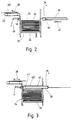
- the stack 64 has reached its desired stack height in the operating position shown in FIG. 2, so that no further copies are briefly fed into the shaft 26.
- the lock 28 is lowered and holds another copy 66 'without the conveyor belt 22 having to be switched off.
- the drive of the press bars 38 and 39 is now put into operation, i.e. 2, to the left, as indicated by an arrow 43, the pressure beams 38 and 39 are moved over the top copy 66 of the stack 64. This run-in can be accomplished in a range of less than one second.
- the two welding punches 58 and 60 now move laterally into the shaft 26 and pull the sleeve 49 over the top of the compressed stack 64.
- the laterally moving press rams 58 and 60 are arranged in a plan view of the shaft between the two pressing beams 38 and 39 resting on the lateral edge region of the stack 64, of course at the level of the band 49, so that they pull them along when they are retracted. So that the retracting welding punches 58 and 60 neither touch the top of the uppermost copy of the pressed stack 64 nor the bottom copy 66 'of the partial stack 68 formed in the meantime on the top 42 of the press beams 38 and 39, their overall height is such that they differ from the The underside 40 of the press bars 38 and 39 extend to a maximum of the upper side 42 thereof.
- the banderole 49 which is looped circumferentially around the pressed stack 64, is welded and at the same time the loop is cut off, as is also known per se from the prior art.
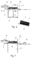
- the welding punches 58 and 60 move back laterally and the banded stack 64 is transferred laterally from the stacking device 12 into the receptacle 62 by lowering and tipping the base 30, as shown in FIG. 6.
- the welding point 70 can be seen on the upper side of the banded stack 64 or the corresponding welding point 72 on the remaining area of the band 49.
- the construction depth, in the representation of FIGS. 1 to 7, of the base 30 is such that it can move in between the spaced-apart press beams 38 and 39, so that the base 30 forms the partial stack 68 formed on the upper side 42 of the press beams 38 and 39 stands out from this.
- FIGS. 8 and 9. the bottom 30 is raised so far that it has just applied to the band 49 from below, and is inserted into the space between the laterally spaced guide bars 38 and 39.
- the floor 30 lifts the partial stack 68 from the upper side 42 or 42 'of the press beams 38 and 39, which up to this point has been used as another floor 44 for the partial stack 68 served.
- the press bars 38 and 39 can be pulled off laterally, as is indicated in FIG. 7 by an arrow 59.
- specimens are continuously fed into the shaft 26 and the partial stack 68 is built up.
- the floor 30 is now gradually lowered until the partial stack 68 which it has meanwhile taken over has reached the stack height shown in FIG. 2.
- the upper sides 42, 42 'of the press bars 38, 39 are designed as roller bottoms, so that the partial stack 68 can then be transferred from the press bars 38 and 39 by quickly pulling them off to the side and thereby fall on the floor 30 raised immediately below, without this then having to move between the two press beams 38 and 39, respectively.
Landscapes
- Engineering & Computer Science (AREA)
- Mechanical Engineering (AREA)
- Basic Packing Technique (AREA)
Claims (6)
- Dispositif pour coller des bandes autour d'exemplaires d'articles imprimés, comprenant un dispositif d'empilement (12), dans lequel les exemplaires (66) sont empilés sur un plateau (30) mobile verticalement en va-et-vient, pour former une pile (64), avec un dispositif de pressage (14) pouvant être amené au-dessus de la pile (64) formée, dispositif sur la face inférieure (40) duquel peut être pressée l'extrémité supérieure de la pile (64) formée afin de comprimer la pile (64), et comprenant un dispositif à coller les bandes (16) afin d'entourer et enserrer la pile (64) dans une bande (49), caractérisé en ce qu'une face supérieure (42) du dispositif de pressage (14) est conformée en plateau supplémentaire (44) sur lequel, pendant la procédure de pressage et de collage de la bande, une pile partielle (68) d'exemplaires (66') est empilée, et en ce que la pile partielle (68) peut être transférée du dispositif de pressage (14) vers le plateau (30) mobile verticalement en va-et-vient.
- Dispositif selon la revendication 1, caractérisé en ce que le plateau (30) mobile verticalement en va-et-vient est conformé en sorte qu'il puisse être introduit verticalement dans le dispositif de pressage (14), et soulève alors la pile partielle (68) reposant sur la face supérieure (42) du dispositif de pressage (14), après quoi le dispositif de pressage (14) peut être sorti de la gaine de déplacement verticale (26) du plateau (30) mobile verticalement en va-et-vient.
- Dispositif selon la revendication 1 ou 2, caractérisé en ce que le dispositif de pressage (14) présente des barres de pressage (38, 39) pouvant être amenées latéralement contre la pile (68), et en ce que le plateau enfonçable (30) peut être introduit verticalement entre les barres de pressage (38, 39) pour soulever la pile partielle (68).
- Dispositif selon l'une des revendications 1 à 3, caractérisé en ce que des tampons à souder (58, 60) du dispositif à coller les bandes (16) peuvent être amenés au-dessus de la pile (68) dans le même sens que le dispositif de pressage (14).
- Dispositif selon la revendication 4, caractérisé en ce que les tampons à souder (58, 60) sont placés entre deux barres de pressage latérales extérieures (38, 39), et en ce que la hauteur des tampons à souder (58, 60) est telle qu'ils s'étendent verticalement entre la face supérieure (42) et la face inférieure (40) du dispositif de pressage (14).
- Dispositif selon l'une des revendications 1 à 5, caractérisé en ce que la face supérieure (42) du dispositif de pressage (14) est conformée en plateau à rouleaux, et en ce que le dispositif de pressage (14) peut être retiré latéralement, en ce que le plateau (30) du dispositif d'empilement (12) peut être élevé approximativement au même niveau que le plateau à rouleaux, et en ce que, lors du retrait latéral du dispositif de pressage (14), la pile partielle (68) formée dessus peut être retenue en arrière et déposée sur le plateau (30) du dispositif d'empilement (12).
Applications Claiming Priority (2)
| Application Number | Priority Date | Filing Date | Title |
|---|---|---|---|
| DE4328136A DE4328136A1 (de) | 1993-08-24 | 1993-08-24 | Einrichtung zum Banderolieren von Exemplaren von Druckerzeugnissen |
| DE4328136 | 1993-08-24 |
Publications (2)
| Publication Number | Publication Date |
|---|---|
| EP0640529A1 EP0640529A1 (fr) | 1995-03-01 |
| EP0640529B1 true EP0640529B1 (fr) | 1996-12-18 |
Family
ID=6495694
Family Applications (1)
| Application Number | Title | Priority Date | Filing Date |
|---|---|---|---|
| EP94110563A Expired - Lifetime EP0640529B1 (fr) | 1993-08-24 | 1994-07-07 | Dispositif pour banderoler des produits d'imprimerie |
Country Status (2)
| Country | Link |
|---|---|
| EP (1) | EP0640529B1 (fr) |
| DE (2) | DE4328136A1 (fr) |
Cited By (1)
| Publication number | Priority date | Publication date | Assignee | Title |
|---|---|---|---|---|
| DE102004008469A1 (de) * | 2004-02-20 | 2005-09-08 | Heidelberger Druckmaschinen Ag | Vorrichtung zum Banderolieren von Stapeln flächiger Werkstücke |
Families Citing this family (9)
| Publication number | Priority date | Publication date | Assignee | Title |
|---|---|---|---|---|
| US5758872A (en) * | 1996-10-23 | 1998-06-02 | Graphic Management Associates, Inc. | Bundling and strapping devices and methods |
| DE19943486A1 (de) * | 1999-09-10 | 2001-03-15 | Giesecke & Devrient Gmbh | Vorrichtung und Verfahren zur Ablage von losem Blattgut |
| DE10113339A1 (de) | 2001-03-20 | 2002-09-26 | Koenig & Bauer Ag | Vorrichtungen und ein Verfahren zum Bündeln eines Stapels von blattartigen Gegenständen |
| DE102006033680A1 (de) * | 2006-07-20 | 2008-01-24 | Saint-Gobain Isover G+H Ag | Verfahren und Vorrichtung zur Herstellung eines Gebindes aus einer Mehrzahl von Einzelpaketen sowie derartiges Gebinde |
| DE102008023900A1 (de) * | 2008-05-16 | 2009-11-19 | Wincor Nixdorf International Gmbh | Einrichtung zum Stapeln von Wertscheinen, insbesondere Banknoten |
| DE102011055992A1 (de) | 2011-12-02 | 2013-06-06 | Wincor Nixdorf International Gmbh | Vorrichtung und Verfahren zum Befüllen eines dünnwandigen Transportbehälters |
| DE102012007773A1 (de) * | 2012-04-20 | 2013-10-24 | Palamides Gmbh | Verfahren und Vorrichtung zum Umreifen eines Stapels von flächigen, flachen Produkten |
| CN114056639B (zh) * | 2020-08-04 | 2025-07-08 | 浙江众大包装设备有限公司 | 一种纸带预压机构和钞把扎把机 |
| DE102022206826A1 (de) * | 2022-07-04 | 2024-01-04 | Volkswagen Aktiengesellschaft | Prozessanordnung zur Fertigung eines Stapelpakets für eine Batteriezelle |
Family Cites Families (8)
| Publication number | Priority date | Publication date | Assignee | Title |
|---|---|---|---|---|
| US3117513A (en) * | 1961-08-14 | 1964-01-14 | Nat Gypsum Co | Insulation batt packaging |
| USRE29372E (en) * | 1974-09-13 | 1977-08-30 | Patco Packing Limited | Apparatus for automatically stacking and compressing batts of compressible material |
| DE2835308A1 (de) * | 1978-08-11 | 1980-02-14 | Gao Ges Automation Org | Verfahren und vorrichtung zum banderolieren von duennem blattgut |
| CH647735A5 (de) * | 1980-07-15 | 1985-02-15 | Grapha Holding Ag | Verfahren zur herstellung von stapeln aus gefalzten druckbogen und vorrichtung zur durchfuehrung des verfahrens. |
| FR2557857A1 (fr) * | 1984-01-05 | 1985-07-12 | Monarch Marking Systems Inc | Machine pour empiler et cercler des etiquettes |
| GB8613760D0 (en) * | 1986-06-06 | 1986-07-09 | Fiberglas Canada Inc | Packaging compressible items |
| US4805383A (en) * | 1988-01-11 | 1989-02-21 | Manville Corporation | Batt packaging machine and method |
| WO1993001060A1 (fr) * | 1991-07-04 | 1993-01-21 | Gunze Limited | Systeme assurant la disposition de feuilles de papier imprimees |
-
1993
- 1993-08-24 DE DE4328136A patent/DE4328136A1/de not_active Withdrawn
-
1994
- 1994-07-07 EP EP94110563A patent/EP0640529B1/fr not_active Expired - Lifetime
- 1994-07-07 DE DE59401314T patent/DE59401314D1/de not_active Expired - Lifetime
Cited By (2)
| Publication number | Priority date | Publication date | Assignee | Title |
|---|---|---|---|---|
| DE102004008469A1 (de) * | 2004-02-20 | 2005-09-08 | Heidelberger Druckmaschinen Ag | Vorrichtung zum Banderolieren von Stapeln flächiger Werkstücke |
| US7207161B2 (en) | 2004-02-20 | 2007-04-24 | Heidelberger Druckmaschinen Ag | Apparatus for banderoling or banding stacks of flat workpieces |
Also Published As
| Publication number | Publication date |
|---|---|
| DE4328136A1 (de) | 1995-03-02 |
| EP0640529A1 (fr) | 1995-03-01 |
| DE59401314D1 (de) | 1997-01-30 |
Similar Documents
| Publication | Publication Date | Title |
|---|---|---|
| DE69008458T2 (de) | Verfahren und Apparat für die Puffersteuerung in Fördersystemen. | |
| EP0847949B1 (fr) | Dispositif pour empiler un chant de feuilles imprimées | |
| EP0156127B1 (fr) | Dispositif pour palettisation | |
| DE3122451A1 (de) | Verfahren und vorrichtung zum stapeln von materialblaettern | |
| DD144900A5 (de) | Vorrichtung zum lagenweisen stapeln von stueckgut auf paletten | |
| DE3113045A1 (de) | Verpackungsmaschine | |
| EP0640529B1 (fr) | Dispositif pour banderoler des produits d'imprimerie | |
| DE2713135A1 (de) | Vorrichtung zum selbsttaetigen verladen von saecken | |
| DE10214684A1 (de) | Fördereinrichtung und Verfahren zur Überführung von Stapeln aus Papier oder dgl. auf einen Abtransportförderer | |
| DE2634634A1 (de) | Stapel- und einfuellvorrichtung fuer bahnteile aus kompressiblem material | |
| DE1277140B (de) | Vorrichtung zum Stapeln und Transportieren von flachen Gegenstaenden, insbesondere Papiertuechern | |
| DE2246877A1 (de) | Vorrichtung zum betrieb eines grossflaechigen silos fuer schuettgut | |
| DE4435981C2 (de) | Einrichtung zum Zuführen von zu verpackenden Produkten zu einer Verpackungsmaschine | |
| DE2920128A1 (de) | Flascheneinpacker | |
| EP0465916B1 (fr) | Dispositif de convoyage pour unités en couches | |
| DE2519341C2 (de) | Vorrichtung zum Beladen mehrerer in einem Ablagegestell angeordneter Tragplatten mit blattartigen Gegenständen | |
| DE4436075C2 (de) | Vorrichtung zum Palettieren von Stückgütern zu einem Stückgutstapel | |
| DE102005002532A1 (de) | Vorrichtung und Verfahren zum automatisierten und zeitgleichen Bereitstellen und Wechseln von mindestens zwei Rollen aus Papierbahnen oder dergleichen für einen nachgeordneten Formatschneider | |
| DE4030643C2 (fr) | ||
| DE1916171B2 (de) | Halbautomatische Palettenpackvorrichtung für Säcke | |
| DE2547298B2 (de) | Verfahren zum aufbau eines stapels vorgegebener laenge und vorrichtung zur durchfuehrung des verfahrens | |
| DE19821918B4 (de) | Verfahren zum Fördern von Produkten und Handhabungseinheit zur Durchführung des Verfahrens | |
| EP0870710A1 (fr) | Méthode et dispositif pour séparer et empiler du courant de transport des articles imprimés | |
| DE3930537C2 (fr) | ||
| DE3712696A1 (de) | Vorrichtung zur paketierung lose und ungeordnet angelieferter formsteine |
Legal Events
| Date | Code | Title | Description |
|---|---|---|---|
| PUAI | Public reference made under article 153(3) epc to a published international application that has entered the european phase |
Free format text: ORIGINAL CODE: 0009012 |
|
| AK | Designated contracting states |
Kind code of ref document: A1 Designated state(s): CH DE FR GB IT LI NL |
|
| 17P | Request for examination filed |
Effective date: 19950401 |
|
| GRAG | Despatch of communication of intention to grant |
Free format text: ORIGINAL CODE: EPIDOS AGRA |
|
| 17Q | First examination report despatched |
Effective date: 19960410 |
|
| GRAH | Despatch of communication of intention to grant a patent |
Free format text: ORIGINAL CODE: EPIDOS IGRA |
|
| GRAH | Despatch of communication of intention to grant a patent |
Free format text: ORIGINAL CODE: EPIDOS IGRA |
|
| GRAA | (expected) grant |
Free format text: ORIGINAL CODE: 0009210 |
|
| AK | Designated contracting states |
Kind code of ref document: B1 Designated state(s): CH DE FR GB IT LI NL |
|
| PG25 | Lapsed in a contracting state [announced via postgrant information from national office to epo] |
Ref country code: NL Free format text: LAPSE BECAUSE OF FAILURE TO SUBMIT A TRANSLATION OF THE DESCRIPTION OR TO PAY THE FEE WITHIN THE PRESCRIBED TIME-LIMIT Effective date: 19961218 Ref country code: IT Free format text: LAPSE BECAUSE OF FAILURE TO SUBMIT A TRANSLATION OF THE DESCRIPTION OR TO PAY THE FEE WITHIN THE PRE;WARNING: LAPSES OF ITALIAN PATENTS WITH EFFECTIVE DATE BEFORE 2007 MAY HAVE OCCURRED AT ANY TIME BEFORE 2007. THE CORRECT EFFECTIVE DATE MAY BE DIFFERENT FROM THE ONE RECORDED.SCRIBED TIME-LIMIT Effective date: 19961218 Ref country code: GB Effective date: 19961218 Ref country code: FR Effective date: 19961218 |
|
| REF | Corresponds to: |
Ref document number: 59401314 Country of ref document: DE Date of ref document: 19970130 |
|
| EN | Fr: translation not filed | ||
| NLV1 | Nl: lapsed or annulled due to failure to fulfill the requirements of art. 29p and 29m of the patents act | ||
| GBV | Gb: ep patent (uk) treated as always having been void in accordance with gb section 77(7)/1977 [no translation filed] |
Effective date: 19961218 |
|
| PG25 | Lapsed in a contracting state [announced via postgrant information from national office to epo] |
Ref country code: LI Free format text: LAPSE BECAUSE OF NON-PAYMENT OF DUE FEES Effective date: 19970731 Ref country code: CH Free format text: LAPSE BECAUSE OF NON-PAYMENT OF DUE FEES Effective date: 19970731 |
|
| PLBE | No opposition filed within time limit |
Free format text: ORIGINAL CODE: 0009261 |
|
| STAA | Information on the status of an ep patent application or granted ep patent |
Free format text: STATUS: NO OPPOSITION FILED WITHIN TIME LIMIT |
|
| 26N | No opposition filed | ||
| REG | Reference to a national code |
Ref country code: CH Ref legal event code: PL |
|
| PGFP | Annual fee paid to national office [announced via postgrant information from national office to epo] |
Ref country code: DE Payment date: 20130724 Year of fee payment: 20 |
|
| REG | Reference to a national code |
Ref country code: DE Ref legal event code: R071 Ref document number: 59401314 Country of ref document: DE |
|
| REG | Reference to a national code |
Ref country code: DE Ref legal event code: R071 Ref document number: 59401314 Country of ref document: DE |
|
| PG25 | Lapsed in a contracting state [announced via postgrant information from national office to epo] |
Ref country code: DE Free format text: LAPSE BECAUSE OF EXPIRATION OF PROTECTION Effective date: 20140708 |