EP0640546A2 - Système d'empilage de feuilles à grande capacité avec introduction et positionnement d'empilage à hauteur variable - Google Patents
Système d'empilage de feuilles à grande capacité avec introduction et positionnement d'empilage à hauteur variable Download PDFInfo
- Publication number
- EP0640546A2 EP0640546A2 EP94305915A EP94305915A EP0640546A2 EP 0640546 A2 EP0640546 A2 EP 0640546A2 EP 94305915 A EP94305915 A EP 94305915A EP 94305915 A EP94305915 A EP 94305915A EP 0640546 A2 EP0640546 A2 EP 0640546A2
- Authority
- EP
- European Patent Office
- Prior art keywords
- stacking
- sheet
- registration
- sheets
- tray
- Prior art date
- Legal status (The legal status is an assumption and is not a legal conclusion. Google has not performed a legal analysis and makes no representation as to the accuracy of the status listed.)
- Granted
Links
- 230000008859 change Effects 0.000 claims abstract description 4
- 230000002452 interceptive effect Effects 0.000 claims abstract 3
- 230000007246 mechanism Effects 0.000 description 7
- 230000008901 benefit Effects 0.000 description 4
- 230000005484 gravity Effects 0.000 description 2
- 230000014759 maintenance of location Effects 0.000 description 2
- 230000004913 activation Effects 0.000 description 1
- 230000001154 acute effect Effects 0.000 description 1
- 230000000903 blocking effect Effects 0.000 description 1
- 230000009194 climbing Effects 0.000 description 1
- 230000000694 effects Effects 0.000 description 1
- 239000002783 friction material Substances 0.000 description 1
- 230000004048 modification Effects 0.000 description 1
- 238000012986 modification Methods 0.000 description 1
- 230000004044 response Effects 0.000 description 1
- 239000007787 solid Substances 0.000 description 1
- 238000011144 upstream manufacturing Methods 0.000 description 1
Images


Classifications
-
- B—PERFORMING OPERATIONS; TRANSPORTING
- B42—BOOKBINDING; ALBUMS; FILES; SPECIAL PRINTED MATTER
- B42C—BOOKBINDING
- B42C1/00—Collating or gathering sheets combined with processes for permanently attaching together sheets or signatures or for interposing inserts
- B42C1/12—Machines for both collating or gathering and permanently attaching together the sheets or signatures
- B42C1/125—Sheet sorters combined with binding devices
-
- B—PERFORMING OPERATIONS; TRANSPORTING
- B65—CONVEYING; PACKING; STORING; HANDLING THIN OR FILAMENTARY MATERIAL
- B65H—HANDLING THIN OR FILAMENTARY MATERIAL, e.g. SHEETS, WEBS, CABLES
- B65H31/00—Pile receivers
- B65H31/02—Pile receivers with stationary end support against which pile accumulates
-
- B—PERFORMING OPERATIONS; TRANSPORTING
- B65—CONVEYING; PACKING; STORING; HANDLING THIN OR FILAMENTARY MATERIAL
- B65H—HANDLING THIN OR FILAMENTARY MATERIAL, e.g. SHEETS, WEBS, CABLES
- B65H2403/00—Power transmission; Driving means
- B65H2403/50—Driving mechanisms
- B65H2403/51—Cam mechanisms
- B65H2403/512—Cam mechanisms involving radial plate cam
-
- B—PERFORMING OPERATIONS; TRANSPORTING
- B65—CONVEYING; PACKING; STORING; HANDLING THIN OR FILAMENTARY MATERIAL
- B65H—HANDLING THIN OR FILAMENTARY MATERIAL, e.g. SHEETS, WEBS, CABLES
- B65H2404/00—Parts for transporting or guiding the handled material
- B65H2404/10—Rollers
- B65H2404/14—Roller pairs
- B65H2404/144—Roller pairs with relative movement of the rollers to / from each other
-
- B—PERFORMING OPERATIONS; TRANSPORTING
- B65—CONVEYING; PACKING; STORING; HANDLING THIN OR FILAMENTARY MATERIAL
- B65H—HANDLING THIN OR FILAMENTARY MATERIAL, e.g. SHEETS, WEBS, CABLES
- B65H2404/00—Parts for transporting or guiding the handled material
- B65H2404/10—Rollers
- B65H2404/15—Roller assembly, particular roller arrangement
- B65H2404/152—Arrangement of roller on a movable frame
- B65H2404/1521—Arrangement of roller on a movable frame rotating, pivoting or oscillating around an axis, e.g. parallel to the roller axis
-
- B—PERFORMING OPERATIONS; TRANSPORTING
- B65—CONVEYING; PACKING; STORING; HANDLING THIN OR FILAMENTARY MATERIAL
- B65H—HANDLING THIN OR FILAMENTARY MATERIAL, e.g. SHEETS, WEBS, CABLES
- B65H2511/00—Dimensions; Position; Numbers; Identification; Occurrences
- B65H2511/10—Size; Dimensions
- B65H2511/15—Height, e.g. of stack
-
- B—PERFORMING OPERATIONS; TRANSPORTING
- B65—CONVEYING; PACKING; STORING; HANDLING THIN OR FILAMENTARY MATERIAL
- B65H—HANDLING THIN OR FILAMENTARY MATERIAL, e.g. SHEETS, WEBS, CABLES
- B65H2801/00—Application field
- B65H2801/24—Post -processing devices
- B65H2801/27—Devices located downstream of office-type machines
Definitions
- This invention relates to a sheet stacking and registration system, and is particularly concerned with a high capacity sheet stacker of a reproduction apparatus.
- Uphill stacking desirably lends itself to stacking registration at an inboard end or side of a reproduction machine and/or a connecting modular stacking unit. That is, at the sheet input side of the stacking tray. It thereby reduces cantilever forces on cantilevered stacking trays. It also automatically slows down the ejected sheets, due to their initial "uphill” movement. The sheets then reverse their movement to slide back down against an upstanding wall or edge adjacent to but underlying the sheet ejection slot or nip. Incoming sheets thus cannot stub on the end of the stack in the tray, if the further sheets enter above the top sheet of the stack, which of course rises with the stack level.
- the stacking registration wall is normally a fixed vertical surface and not an integral upstanding end of the tray itself, as in a sorter bin or other conventional stacking tray. That is, the registration surface against which the incoming copy sheets are registered is typically the vertical surface of the end of the machine or the stacking tray elevator itself, against which the sets can register or align as they stack.
- the first incoming sheets would be be required to drop a substantial distance before coming to rest on the top of the stack or tray.
- This large drop distance tends to increase the number of stacking problems, such as sheets or sets coming to rest in an orientation other than flat against the top of the stack, and/or substantial scatter within the stack.
- outputted sheets are usually ejected into the stacking tray from above one end thereof.
- Normal output stacking is by ejecting sheets from above one end of the top sheet of the stack of sheets onto which that additional ejected sheet or sheets must also stack.
- each sheet is ejected generally horizontally (or slightly uphill initially) and continues to move horizontally primarily by inertia. That is, stacking sheets are not typically effectively controlled or guided once they are released into the stacking tray area.
- orbital nip stacking system of US-A-5,201,577, cited below. The sheets fall by gravity into the tray to settle onto the top of the stack.
- a desired sheet ejection level should accommodate variations in the pre-existing height of the stack of sheets already in the tray (varying with the set size, sheet thickness, and number of sheets stacked in the tray since it was last cleared).
- a tray elevator is normally provided to maintain a relatively constant stack height position relative to the sheet output ejection position for high capacity stackers.
- a sheet stacking and registration apparatus in which sheets are fed by a sheet feeder onto a stacking tray to form a sheet stack which is registered against a registration edge, characterised in that both the sheet feeder and the registration edge are mounted for movement during stacking so that both maintain a substantially constant relationship with the top of the stack.
- the system disclosed herein overcomes the above and other problems, without requiring a tray elevator, yet without sacrificing the desired output and stacking positions for the outputted sheets.
- the disclosed system provides improved output stacking of multiple printed sheets, such as multiple sets or jobs of flimsy copy sheets sequentially outputted by a copier or printer, with overall stack alignment for subsequent handling, particularly for large stacks, at relatively low cost, and without sacrificing desired inclined stacking and registration orientations. Further so disclosed is a stacking system that does not require a movable stacking tray with a tray elevator, and can provide a simple fixed stacking tray by providing a variable height stacking registration wall and a variable sheet input level to the stacking tray.
- the disclosed sheet output stacking system has particular utility or application for high-capacity stacking of pre-collated copy output sheet sets from a copier or printer, which may include a compiler and finisher, where such output may require stacking relatively large numbers of completed copy sets in a relatively high stack.
- Such stacked copy sets may be unfinished, or may be stapled, glued, bound, or otherwise finished and/or offset.
- High capacity stackers are particularly desirable for the collected output of high speed or plural job batching copiers or printers. High capacity stackers (usually with job offsetting) are also often used for the accumulated output of unattended plural user (networked) printers, of any speed.
- the disclosed system provides a high capacity sheet stacking system for stacking substantial quantities of the sequential sheet output of a reproducing apparatus on a sheet stacking tray providing an inclined sheet stacking surface at a substantial angle from the horizontal for receiving and registering sheets against an upstanding stack edge registration or alignment surface.
- this stack edge alignment surface is automatically varied in height above the stacking surface with the change in stack height in the tray, in coordination with vertical repositioning of the sheet input level to the tray with stack height, so that an elevator system is not required for the stacking tray, and a simple fixed position tray may be used.
- variable input level stacking system is particularly compatible or combinable with, or integrateable into, a plural tray or bin sorter or mailbox unit, wherein the variable level sheet input for the stacker can also be conventionally used as a bin or tray selector, so as to provide either selected bin stacking or high capacity tray stacking in the same integral output unit sharing common hardware for cost savings.
- the present invention is not limited to the specific embodiments illustrated herein.
- the specific exemplary embodiments disclosed show "uphill" high-capacity stacking trays with an inclined stacking surface at a desired stacking angle to the horizontal, which stacking tray or trays may be an integral part of a multi-bin sorter or mailbox unit. That unit or module may also provide other conventional, low capacity trays with conventional fixed low height registration end walls.
- the stacking tray here has a sheet stacking registration wall at the inside, lower, end of the stacking surface which is approximately perpendicular to the stacking surface. It may be at a more acute angle than that for space savings reasons, as shown, so as not to interfere with vertical movement of a sheet input system therepast, and allow the sheet input to be closely adjacent the downstream end of the stacking tray.
- FIG. 1 there is shown one example 10 of the subject variable height registration wall sheet stacking system.
- a somewhat different exemplary stacking system 11 is shown in two examples in Fig. 3.
- This stacking system 10 may be part of a "mailbox" module 12, with plural mailbox bins, receiving outputted copy sheets 14 from a printer.
- the system 10, 11, or the like could be in various other stackers, sorters, compiler/finisher units, or other output modules, or integral with the printer itself.
- the stacking system 10 or 11 or the like may also be a self-contained, stand-alone or independent high capacity stacking unit, wheeled up to and docked with any reproduction apparatus, when desired.
- This stacking system 10 or 11 here has at least one "uphill" stacking tray 18 with a sheet input 20 indirectly from a printer to provide improved output sheets 14 stacking and control.
- This stacking system 10 or 11 is a high-capacity type stacker system. That is, the sheet receiving and stacking system 10 can stack a large number of the sheets 14 into tray 18 in a neat, registered, high stack 22 on stacking surface 18a.
- the upstream end of the tray 18 is closely adjacent the sheet input 20, for being fed sheets, or sets of sheets, for stacking.
- the exemplary stacking system 10 may utilize an otherwise conventional fixed copy sheet output tray as stacking tray 18, since no tray elevator system is required.
- the sheet input 20 is vertically movable instead. It may be mounted in a linear, vertical, elevator track to be moved by any suitable elevator drive system or lift mechanism, such as a servo or stepper motor, to provide a moving sheet input 20 for the accumulating stack of sheets in the stacking tray unit 14.
- Suitable elevator mechanisms known and/or shown in the art for moving stacking trays may be used here instead to move the sheet input system 20.
- These include US-A-5,026,034, Fig. 2, US-A-4,925,171; US-A-5,137,265; US-A-3,414,254. It may be a cable, ratchet, lead screw, parallelogram linkage, or other suitable elevator movement mechanism.
- a detailed vertical elevator drive system is also shown and described in the above-cited US-A-5,098,074.
- the moveable sheet input 20 here is a vertically repositionable compiler, stacker/stapler/set ejector known per se and described in the above-cited applications, etc., and thus need not be described in detail. If there is more than one tray, the desired tray 18 may be selected by the vertical position of the compiler unit 20. Sheets are deflected from a conventional vertical sheet transport by a deflector and input rollers nip, as shown by the dashed line with arrow, into a partial compiler shelf 20a, where the sheets 14 are compiled into job sets, and stapled at 20b.
- the set is then ejected by arm 20c (with an end roller), pivoting down to form an ejecting nip with underlying roller 20d to feed the compiled set off the compiler shelf 20a into the tray 18
- the compiler shelf 20a end 20e determines the set ejection level.
- arm 20c may be pivoted by a cam 50 driven by motor 52.
- the Fig. 5 example uses a different set ejector with ejector fingers, like that of the above-cited U.S. 5,098,074, etc.
- the movable sheet input 20 can be much lighter than the weight of a stacking tray loaded with a large stack of copy sheets.
- the tray 18 here does not need to move.
- a simple, lighter, cheaper and faster elevator system can be used here than for a conventional moving tray stacker system.
- the movable sheet input unit 20 can be a simple moving gate sheet deflector as in said US-A-3,414,254, or a moving compiler/stapler unit such as 20, as described in the above-cited co-pending applications and references. In either case, the sheet input level to the stacking tray 18 automatically rises vertically as the top of the stack rises, (as the tray 18 fills) by repositioning the sheet input unit 20.
- control logic in a conventional controller can be used to count the total number of outputted sheets since the tray was last emptied, to provide an approximate determination of the stack 22 height, and provide corresponding repositioning control signals in response thereto.
- these stack height signals may be fed here to a stepper motor drive to effect a corresponding change in sheet input 20 height.
- the exemplary embodiments 10 and 11 here have stacking trays 18 providing an inclined stacking surface 18a at a desired stacking angle from the horizontal sufficient to slide stacking sheets down against the upstanding sheet stacking registration edge, surface or end wall at the lower end of the stacking surface 18a.
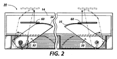
- the variable height end wall system 30 example is shown in Figs. 1 and 2
- the system 40 example is shown in Fig. 3.
- the stacking system 30 or 40 here registers each incoming (top) sheet, maintains edge alignment or squaring of the entire stack end, and keeps any part of the stack 22 from sliding off the tray 18, even as the stack 22 greatly increases in height.
- This stacking edge alignment system 30 or 40 is not fixed in height here, as in a conventional tray stacking system. It moves to increase in height automatically to stay above the top of the stack 22, while keeping a constant relationship with the sheet input 20. That is, the stack registration and edge alignment system 30 or 40 herein provides high capacity "uphill” set stacking into a fixed tray by providing a movable "backstop” (or bin rear registration edge) which moves up (increases in height) with the moving sheet input level. I.e., the backstop system 30 or 40 moves up the back of the stack as the stack height increases and the compiler moves up.
- elongated rigid backstop registration arms 32, 33 are pivotally mounted to tray 18, or its mounting frame, and spring loaded to pivot up transversely of the tray 18 as the compiler or other sheet input 20 rises relative to this fixed tray 18 (as the stack level rises).
- These arms 32, 33, or the like, and their mountings provide sufficient rigidity to provide a consistent downhill end registration wall or edge even for heavy (high) stacks. They provide a variable height registration wall system 30 for a high capacity stacking system.
- This pivotal movement of arms 32, 33 can be somewhat like windshield wipers or scissors. Note the movement arrows in Fig. 2.
- the arms 32, 33 may be longer than those illustrated, and may even cross each other when held down, to increase the maximum stacking capacity.
- pivotal stack end retainers 32, 33 desirably automatically stay up with a stack there against so as not to require stack unloading before moving the sheet input unit 20 (compiler or input gate) down again.
- the arms 32, 33 should be movable down, e.g., by the sheet input unit 20 when the tray 18 is empty or substantially empty, so the sheet input 20 will not be too high above the tray bottom surface 18a for the start of stacking, as discussed above.
- a cam 50 driven by motor 52 moves a pivotal latch 60, both mounted to the sheet input unit 20.
- the latch 60 engages tabs 34 and 35 respectively on arms 32 and 33.
- the tabs 34 and 35 push the arms 32, 33 down to a position determined by the position of the sheet input unit.
- the sheet input unit 20 moves upward.
- the arms 32, 33 remain spring loaded against latch 60 as the sheet input unit 20 moves upward, thereby automatically extending the arms 32, 33 to accommodate an increasingly higher stack.
- cam 50 causes latch 60 to retract, to thereby remove its contact with tabs 34 and 35 on arms 32 and 33.
- the spring load on arms 32 and 33 rotates them to their highest, most vertically extended (e.g., 75-80 degree), positions.
- This second position of latch 60 allows sheet input unit 20 to move on to the next lower tray.
- Latch 60 is retracted by cam 50 only for a short time to release the spring loaded arms on the first tray, then moved back to its initial position so as to engage tabs 34 and 35 on the next lower tray. [Only one tray is shown in Figs. 1 and 2.]
- stacking system 11 with a different variable height registration wall system 40, of Fig. 3, it also provides high capacity "uphill” set stacking into fixed trays or bins 18.
- the system 40 is providing a flexible "backstop" 42 (or bin rear registration surface) which moves up (increases in height) with the moving compiler/set ejector unit 20.
- the backstop 42 here is a flexible belt (or belts) that unrolls up the back of the stack as the stack height increases and the compiler unit 20 moves up.
- Two identical such systems for two identical such high capacity stackers 18 are shown in Fig. 3 in one unit.
- the flexible belt backstop 42 here is partially supported or backed up with a rigid frame member or backing plate 44 attached to and moving with the belt 42 traveling carriage to support the weight of the upper portion of the stack, as illustrated in Fig. 3.
- This backing plate 44 slides up the back side of the belt 43, which should be a low friction material.
- the backing plate member 44 no longer backs up the portion of the stack below the member 44. That is not necessary at that point, since the lowest portions of the stack are restrained from sliding downhill by a rigid rear wall portion 46 of the tray, and the top of the stack is prevented from sliding downhill (and thereby restrained from "bowing" the windowshade) by the aforementioned rigid frame member 44 of the windowshade support carriage.
- the middle (unbacked) portion of the stack will not slide downhill because there is substantial sheet to sheet friction and substantial normal force from the portions of the stack piled above that central section of the stack.
- the flexible backstop stacking mechanism of system 11 automatically stays out of the way of incoming sheets. It is affixed to the sliding carriage 20, which supports two rollers that define the shape of the flexible backstop 42. This is not a "windowshade” mechanism. It is a flexible belt 42 with both ends fixed. It is more akin to a "Rolomite” bearing than to a windowshade. A major benefit of this geometry and mechanism is that the backstop 42 does not slide relative to the edge of the stack as would happen with a windowshade [unless it were unrolled from above the stack]. Rather, the backstop 42 is rolled up against the edge of the stack, so that there is no sliding motion.
- the two rollers on the sliding carriage simply bend the belt into the shape of an "S" lying on its side. As the sliding carriage moves up or down, the location of the S-bend moves with it.
- the top anchored portion of the belt 42 which is always located on the right side of the sliding carriage, has a large rectangular hole in it to allow sheets to pass through the belt.
- the bottom anchored portion of the belt 42 which may always be located to the left of the carriage and partially snaked through the carriage in the "S" path, is preferably solid (unapertured) in order to function as a backstop for any size sheets as the stack grows and the carriage elevates.
- various other mechanisms or modifications will be available to those skilled in the art.
- an advantage of this flexible belt 42 version 40 of the variable height registration stacking wall is that as the belt 42 unrolls to accommodate increasing stack height, there is no relative motion between this backstop member 42 and the registered edge of the stack. Thus, there are no forces to lift the edge of the stack, or disturb it in any other way. This will help keep the stack edge flat and neat. Also, the height of the stack is limited only by the length of the belt selected, and/or its unscrolling system.
- the latch 60 is operated by a solenoid 62 rather than a rotating cam 50 as in Figs. 1 and 2.
- the activation or timing may be similar to that described previously.
- Set ejector arm 20c may also be solenoid activated, if desired.
- the pivoted latch arm 60 is shown otherwise similarly provided under the compiler shelf 20a on the traveling elevator carriage assembly 20. Here, in its forward or downstream position, the operative end of the latch arm 60 engages and holds the backstop control tabs 48, allowing them to move up only with the upward movement of the carriage assembly 20.
- a fixed stacking tray with a high fixed end wall would be impractical for a high capacity stacker, which does not have a tray elevator for moving the tray down as it fills.
- a compiler or other tray input can't feed into the tray if the registration end wall is too high and in the way (blocking sheet input). Also, if the tray end wall is too high and the compiler/ejector or other sheet input feeds in over the top of a high end wall into an empty bin, the first ejected sets would have too far to drop, and could be scattered or disoriented or even buckled or folded over.
- a shared (partial) compiler shelf/stack support compiling system could not then be used, either since the compiling set outer end would hang down too far, or even pull off of the short compiler shelf.
- shared compiler tray systems require the top of the stack to be maintained adjacent the compiler shelf level to help support the compiling set. Normally, that is done by moving the tray down as it fills. Here, the compiler or other input feeder moves up as the tray fills, and so does the stack registration end wall, with the tray input, but under it.
- an integral or related copy set compiler/stapler or other finisher can desirably be provided prior to stacking. It can be integrated with the vertically repositionable sheet input 20 to the stacking tray 18.
- Such units, per se are disclosed in the above-cited US-A-5,098,074, or the above-cited US-A-5,201,517.
- a compiler/finisher unit if provided, is desirably vertically movable directly adjacent to the stacking tray, as disclosed in the two above cross-referenced copending applications, and further illustrated herein.
- the automatic variable height stacking end wall system 30 or 40 here is equally or even more usable with a fixed tray stacker combined into a simple fixed bins moving gate type sorter, where no moving compiler is required.
- a fixed tray stacker combined into a simple fixed bins moving gate type sorter, where no moving compiler is required.
- stationary bin sorters with an additional common, top, or stacking tray.
- Such sorters can, however, optionally provide in-bin stapling, as is well known.
- a moving gate for a sorter can be very light-weight, simple, vertically repositionable sheet deflector taking sheets from a vertical sorter transport wherever it is vertically positioned to deflect the sheets into the adjacent selected sorter bin.
- a compiler/stapler/set ejector unit for both a mailbox for a printer and for sorter (collator) [for a non-pre-collation copier] is probably not cost effective, as sorters can be made cheaper and faster if they do not have to provide a heavier and larger compiler unit and its elevator to move rapidly vertically between bins to put only one sheet into each bin at a time, as is required for sorting.
- copy sheet output stacking is described herein, it will be appreciated that there may be extended applications for the present concept, such as for use for a document "job batching" restacker, for accumulating several job sets of original documents and restacking them after plural sequential unattended document copying or scanning jobs have been completed.
- the sheet input 20 may have output or exit ejection feed rollers and/or a deflector extending out slightly over (beyond, or downstream of) the plane of registration wall system 30.
- the lower exit rollers shaft may also desirably include known flexible sheet flappers. This helps control upcurled sheet ends in uphill stacking. In that case, the input 20 elevator system may be controlled to keep the top of the stack relatively close to the lower sheet ejection rollers or said flappers effective are to help keep the stacked sheets pressed down and preventing them from "climbing" up the registration wall 30 or 40.
Landscapes
- Engineering & Computer Science (AREA)
- Mechanical Engineering (AREA)
- Pile Receivers (AREA)
- Collation Of Sheets And Webs (AREA)
- Discharge By Other Means (AREA)
Applications Claiming Priority (2)
| Application Number | Priority Date | Filing Date | Title |
|---|---|---|---|
| US113004 | 1993-08-30 | ||
| US08/113,004 US5346203A (en) | 1993-08-30 | 1993-08-30 | High capacity sheet stacking system with variable height input and stacking registration |
Publications (3)
| Publication Number | Publication Date |
|---|---|
| EP0640546A2 true EP0640546A2 (fr) | 1995-03-01 |
| EP0640546A3 EP0640546A3 (fr) | 1996-04-17 |
| EP0640546B1 EP0640546B1 (fr) | 1997-12-10 |
Family
ID=22347056
Family Applications (1)
| Application Number | Title | Priority Date | Filing Date |
|---|---|---|---|
| EP94305915A Expired - Lifetime EP0640546B1 (fr) | 1993-08-30 | 1994-08-10 | Système d'empilage de feuilles à grande capacité avec introduction et positionnement d'empilage à hauteur variable |
Country Status (4)
| Country | Link |
|---|---|
| US (1) | US5346203A (fr) |
| EP (1) | EP0640546B1 (fr) |
| JP (1) | JPH0781832A (fr) |
| DE (1) | DE69407236T2 (fr) |
Families Citing this family (24)
| Publication number | Priority date | Publication date | Assignee | Title |
|---|---|---|---|---|
| US5540421A (en) * | 1993-07-30 | 1996-07-30 | Canon Kabushiki Kaisha | Book binding apparatus |
| JP2801501B2 (ja) * | 1993-08-06 | 1998-09-21 | シャープ株式会社 | 用紙後処理装置 |
| US5409201A (en) * | 1994-03-18 | 1995-04-25 | Xerox Corporation | Integral disk type inverter-stacker and stapler with sheet stacking control |
| US5462265A (en) * | 1994-11-07 | 1995-10-31 | Xerox Corporation | Variable force sheets or set ejector |
| US6241234B1 (en) * | 1996-12-27 | 2001-06-05 | Canon Kabushiki Kaisha | Sheet processing apparatus and image forming apparatus using same |
| US5884910A (en) * | 1997-08-18 | 1999-03-23 | Xerox Corporation | Evenly retractable and self-leveling nips sheets ejection system |
| US6422557B1 (en) * | 1997-09-12 | 2002-07-23 | Canon Kabushiki Kaisha | Image forming apparatus having a plurality of sheet stacking means |
| US6279892B1 (en) * | 1998-04-17 | 2001-08-28 | Minolta Co., Ltd. | Image forming apparatus with highly operable sheet discharge device |
| US6307163B1 (en) * | 1999-04-02 | 2001-10-23 | United Microelectronics Corp. | Chemical mixer tank calibrator and calibrating method for the same |
| US6572293B1 (en) | 2000-09-14 | 2003-06-03 | Electronics For Imaging, Inc. | Simple and inexpensive high-capacity output catch tray for document production machines |
| US6454255B1 (en) * | 2000-12-19 | 2002-09-24 | Pitney Bowes Inc. | Recirculating gripper accumulator having a circular paper path |
| US6942206B2 (en) * | 2001-08-31 | 2005-09-13 | Canon Kabushiki Kaisha | Sheet treating apparatus and image forming apparatus having the same |
| JP4708081B2 (ja) * | 2005-04-28 | 2011-06-22 | キヤノンファインテック株式会社 | シート処理装置、および画像形成装置 |
| JP4920939B2 (ja) * | 2005-09-28 | 2012-04-18 | キヤノン株式会社 | シート排出装置及び画像形成装置 |
| JP4511458B2 (ja) * | 2005-12-29 | 2010-07-28 | 東芝テック株式会社 | 用紙後処理装置 |
| JP4523572B2 (ja) * | 2006-07-10 | 2010-08-11 | シャープ株式会社 | 排紙積載器 |
| US7533879B2 (en) * | 2007-09-18 | 2009-05-19 | Xerox Corporation | Variable frequency tampers for coated stocks used in paper feed trays |
| US8348259B2 (en) * | 2008-08-12 | 2013-01-08 | Xerox Corporation | Sensors and variable positioned lift plates for laminated stocks in paper trays with a top vacuum feeder |
| CN102745540A (zh) * | 2011-04-22 | 2012-10-24 | 致伸科技股份有限公司 | 纸张整列及排出机构 |
| US8631925B1 (en) * | 2012-09-12 | 2014-01-21 | Processing Technologies, Llc | Adjusting mechanism for rolls on a roll stand assembly |
| US8844920B1 (en) | 2013-06-14 | 2014-09-30 | Xerox Corporation | Stapler producing high precision alignment stacking of unstapled sheets |
| US9206010B2 (en) | 2013-12-23 | 2015-12-08 | Xerox Corporation | Cycling media support for compiled sets using one motor direction |
| US11072509B2 (en) | 2017-07-31 | 2021-07-27 | Hewlett-Packard Development Company, L.P. | Media stops |
| CN112340512A (zh) * | 2020-12-17 | 2021-02-09 | 深圳市研迅诚科技有限公司 | 一种纸张堆叠机构 |
Family Cites Families (12)
| Publication number | Priority date | Publication date | Assignee | Title |
|---|---|---|---|---|
| US3907279A (en) * | 1970-08-24 | 1975-09-23 | Addressograph Multigraph | Collating device |
| US4361320A (en) * | 1978-12-21 | 1982-11-30 | Ricoh Company, Ltd. | Sheet distribution method and apparatus |
| JPS5593765A (en) * | 1978-12-29 | 1980-07-16 | Ricoh Co Ltd | Collater |
| JPS5934908Y2 (ja) * | 1979-03-07 | 1984-09-27 | 株式会社リコー | コレ−タ |
| JPS56146147A (en) * | 1980-04-15 | 1981-11-13 | Ricoh Co Ltd | Copying machine provided with gathering device |
| JPS61217464A (ja) * | 1985-03-18 | 1986-09-27 | Canon Inc | 仕分けトレイ装置 |
| JPS62201769A (ja) * | 1985-11-19 | 1987-09-05 | Olympus Optical Co Ltd | シ−ト類仕分け装置 |
| JPS62140971A (ja) * | 1985-12-11 | 1987-06-24 | Matsushita Electric Ind Co Ltd | シ−ト収納トレイ |
| US5026034A (en) * | 1989-06-19 | 1991-06-25 | Eastman Kodak Company | Document output apparatus having anti-dishevelment device |
| JPH03140297A (ja) * | 1989-10-27 | 1991-06-14 | Canon Inc | ソータ |
| US5098074A (en) * | 1991-01-25 | 1992-03-24 | Xerox Corporation | Finishing apparatus |
| ES2110697T3 (es) * | 1993-04-27 | 1998-02-16 | Xerox Corp | Sistema de encasillado y clasificador para suministrar hojas desde un dispositivo de salida al interior de las casillas bloqueables de un buzon. |
-
1993
- 1993-08-30 US US08/113,004 patent/US5346203A/en not_active Expired - Fee Related
-
1994
- 1994-08-10 EP EP94305915A patent/EP0640546B1/fr not_active Expired - Lifetime
- 1994-08-10 DE DE69407236T patent/DE69407236T2/de not_active Expired - Fee Related
- 1994-08-25 JP JP6200735A patent/JPH0781832A/ja active Pending
Also Published As
| Publication number | Publication date |
|---|---|
| DE69407236D1 (de) | 1998-01-22 |
| EP0640546A3 (fr) | 1996-04-17 |
| DE69407236T2 (de) | 1998-07-09 |
| EP0640546B1 (fr) | 1997-12-10 |
| JPH0781832A (ja) | 1995-03-28 |
| US5346203A (en) | 1994-09-13 |
Similar Documents
| Publication | Publication Date | Title |
|---|---|---|
| EP0640546B1 (fr) | Système d'empilage de feuilles à grande capacité avec introduction et positionnement d'empilage à hauteur variable | |
| CA2172194C (fr) | Dispositif d'empilage et de positionnement de feuilles pour machine de reproduction haute vitesse | |
| CA2140413C (fr) | Agrafeuse et inverseuse-empileuse de type a disque | |
| US7552923B2 (en) | Simple and inexpensive high capacity output catch tray for document production machines | |
| US5318401A (en) | Stacking tray system with nonvertically receding elevator yielding square stacks | |
| CA2140414C (fr) | Agrafeuse et inverseuse-empileuse de type a disque, avec commande d'empilement des feuilles | |
| US5370384A (en) | Sheet transport belt and support system for a sorter or mailbox | |
| US5462265A (en) | Variable force sheets or set ejector | |
| CA2122499C (fr) | Dispositif integre d'acheminement et d'empilage de feuilles pour machines a copier | |
| US5120047A (en) | Integral sheet stacking buckle suppressor and registration edge | |
| US5443249A (en) | In-bin stapling system with interactive registration wall | |
| AU2001287069A1 (en) | High-Capacity output catch tray for document production machines | |
| US6378864B1 (en) | Stacker | |
| US5120046A (en) | Automatically spaced sheet stacking baffle | |
| US5054766A (en) | Paper positioning device | |
| US5152515A (en) | Variable trajectory document restacking system | |
| EP0673868B1 (fr) | Dispositif de retournement et d'empilage à disque avec une agrafeuse intégrée | |
| USH1781H (en) | Automatically retractable extending nip sheet ejection system for a multiple output locations stacking device | |
| JP3371117B2 (ja) | 排紙処理装置 | |
| JPH0399894A (ja) | 用紙後処理装置 |
Legal Events
| Date | Code | Title | Description |
|---|---|---|---|
| PUAI | Public reference made under article 153(3) epc to a published international application that has entered the european phase |
Free format text: ORIGINAL CODE: 0009012 |
|
| AK | Designated contracting states |
Kind code of ref document: A2 Designated state(s): DE FR GB |
|
| PUAL | Search report despatched |
Free format text: ORIGINAL CODE: 0009013 |
|
| RHK1 | Main classification (correction) |
Ipc: B65H 31/02 |
|
| AK | Designated contracting states |
Kind code of ref document: A3 Designated state(s): DE FR GB |
|
| 17P | Request for examination filed |
Effective date: 19961017 |
|
| 17Q | First examination report despatched |
Effective date: 19961115 |
|
| GRAG | Despatch of communication of intention to grant |
Free format text: ORIGINAL CODE: EPIDOS AGRA |
|
| GRAG | Despatch of communication of intention to grant |
Free format text: ORIGINAL CODE: EPIDOS AGRA |
|
| GRAH | Despatch of communication of intention to grant a patent |
Free format text: ORIGINAL CODE: EPIDOS IGRA |
|
| GRAH | Despatch of communication of intention to grant a patent |
Free format text: ORIGINAL CODE: EPIDOS IGRA |
|
| GRAA | (expected) grant |
Free format text: ORIGINAL CODE: 0009210 |
|
| AK | Designated contracting states |
Kind code of ref document: B1 Designated state(s): DE FR GB |
|
| REF | Corresponds to: |
Ref document number: 69407236 Country of ref document: DE Date of ref document: 19980122 |
|
| ET | Fr: translation filed | ||
| PLBE | No opposition filed within time limit |
Free format text: ORIGINAL CODE: 0009261 |
|
| STAA | Information on the status of an ep patent application or granted ep patent |
Free format text: STATUS: NO OPPOSITION FILED WITHIN TIME LIMIT |
|
| 26N | No opposition filed | ||
| PGFP | Annual fee paid to national office [announced via postgrant information from national office to epo] |
Ref country code: DE Payment date: 20010806 Year of fee payment: 8 |
|
| PGFP | Annual fee paid to national office [announced via postgrant information from national office to epo] |
Ref country code: GB Payment date: 20010808 Year of fee payment: 8 |
|
| PGFP | Annual fee paid to national office [announced via postgrant information from national office to epo] |
Ref country code: FR Payment date: 20010810 Year of fee payment: 8 |
|
| REG | Reference to a national code |
Ref country code: GB Ref legal event code: IF02 |
|
| PG25 | Lapsed in a contracting state [announced via postgrant information from national office to epo] |
Ref country code: GB Free format text: LAPSE BECAUSE OF NON-PAYMENT OF DUE FEES Effective date: 20020810 |
|
| PG25 | Lapsed in a contracting state [announced via postgrant information from national office to epo] |
Ref country code: DE Free format text: LAPSE BECAUSE OF NON-PAYMENT OF DUE FEES Effective date: 20030301 |
|
| GBPC | Gb: european patent ceased through non-payment of renewal fee |
Effective date: 20020810 |
|
| PG25 | Lapsed in a contracting state [announced via postgrant information from national office to epo] |
Ref country code: FR Free format text: LAPSE BECAUSE OF NON-PAYMENT OF DUE FEES Effective date: 20030430 |
|
| REG | Reference to a national code |
Ref country code: FR Ref legal event code: ST |