EP0640679B1 - Procédé d'oxydation partielle et brûleur avec paroi frontale poreuse - Google Patents
Procédé d'oxydation partielle et brûleur avec paroi frontale poreuse Download PDFInfo
- Publication number
- EP0640679B1 EP0640679B1 EP93306867A EP93306867A EP0640679B1 EP 0640679 B1 EP0640679 B1 EP 0640679B1 EP 93306867 A EP93306867 A EP 93306867A EP 93306867 A EP93306867 A EP 93306867A EP 0640679 B1 EP0640679 B1 EP 0640679B1
- Authority
- EP
- European Patent Office
- Prior art keywords
- conduit
- burner
- porous
- central
- tip
- Prior art date
- Legal status (The legal status is an assumption and is not a legal conclusion. Google has not performed a legal analysis and makes no representation as to the accuracy of the status listed.)
- Expired - Lifetime
Links
Images
Classifications
-
- C—CHEMISTRY; METALLURGY
- C01—INORGANIC CHEMISTRY
- C01B—NON-METALLIC ELEMENTS; COMPOUNDS THEREOF; METALLOIDS OR COMPOUNDS THEREOF NOT COVERED BY SUBCLASS C01C
- C01B3/00—Hydrogen; Gaseous mixtures containing hydrogen; Separation of hydrogen from mixtures containing it; Purification of hydrogen; Reversible storage of hydrogen
- C01B3/02—Production of hydrogen; Production of gaseous mixtures containing hydrogen
- C01B3/32—Production of hydrogen; Production of gaseous mixtures containing hydrogen by reaction of gaseous or liquid organic compounds with gasifying agents, e.g. water, carbon dioxide or air
- C01B3/34—Production of hydrogen; Production of gaseous mixtures containing hydrogen by reaction of gaseous or liquid organic compounds with gasifying agents, e.g. water, carbon dioxide or air by reaction of hydrocarbons with gasifying agents
- C01B3/36—Production of hydrogen; Production of gaseous mixtures containing hydrogen by reaction of gaseous or liquid organic compounds with gasifying agents, e.g. water, carbon dioxide or air by reaction of hydrocarbons with gasifying agents using oxygen; using mixtures containing oxygen as gasifying agents
- C01B3/363—Production of hydrogen; Production of gaseous mixtures containing hydrogen by reaction of gaseous or liquid organic compounds with gasifying agents, e.g. water, carbon dioxide or air by reaction of hydrocarbons with gasifying agents using oxygen; using mixtures containing oxygen as gasifying agents characterised by the burner
-
- C—CHEMISTRY; METALLURGY
- C10—PETROLEUM, GAS OR COKE INDUSTRIES; TECHNICAL GASES CONTAINING CARBON MONOXIDE; FUELS; LUBRICANTS; PEAT
- C10J—PRODUCTION OF PRODUCER GAS, WATER-GAS, SYNTHESIS GAS FROM SOLID CARBONACEOUS MATERIAL, OR MIXTURES CONTAINING THESE GASES; CARBURETTING AIR OR OTHER GASES
- C10J3/00—Production of combustible gases containing carbon monoxide from solid carbonaceous fuels
- C10J3/46—Gasification of granular or pulverulent flues in suspension
- C10J3/48—Apparatus; Plants
- C10J3/50—Fuel charging devices
- C10J3/506—Fuel charging devices for entrained flow gasifiers
-
- F—MECHANICAL ENGINEERING; LIGHTING; HEATING; WEAPONS; BLASTING
- F23—COMBUSTION APPARATUS; COMBUSTION PROCESSES
- F23D—BURNERS
- F23D14/00—Burners for combustion of a gas, e.g. of a gas stored under pressure as a liquid
- F23D14/46—Details
- F23D14/72—Safety devices, e.g. operative in case of failure of gas supply
- F23D14/78—Cooling burner parts
-
- C—CHEMISTRY; METALLURGY
- C01—INORGANIC CHEMISTRY
- C01B—NON-METALLIC ELEMENTS; COMPOUNDS THEREOF; METALLOIDS OR COMPOUNDS THEREOF NOT COVERED BY SUBCLASS C01C
- C01B2203/00—Integrated processes for the production of hydrogen or synthesis gas
- C01B2203/02—Processes for making hydrogen or synthesis gas
- C01B2203/025—Processes for making hydrogen or synthesis gas containing a partial oxidation step
- C01B2203/0255—Processes for making hydrogen or synthesis gas containing a partial oxidation step containing a non-catalytic partial oxidation step
-
- C—CHEMISTRY; METALLURGY
- C10—PETROLEUM, GAS OR COKE INDUSTRIES; TECHNICAL GASES CONTAINING CARBON MONOXIDE; FUELS; LUBRICANTS; PEAT
- C10J—PRODUCTION OF PRODUCER GAS, WATER-GAS, SYNTHESIS GAS FROM SOLID CARBONACEOUS MATERIAL, OR MIXTURES CONTAINING THESE GASES; CARBURETTING AIR OR OTHER GASES
- C10J2200/00—Details of gasification apparatus
- C10J2200/15—Details of feeding means
- C10J2200/152—Nozzles or lances for introducing gas, liquids or suspensions
-
- C—CHEMISTRY; METALLURGY
- C10—PETROLEUM, GAS OR COKE INDUSTRIES; TECHNICAL GASES CONTAINING CARBON MONOXIDE; FUELS; LUBRICANTS; PEAT
- C10J—PRODUCTION OF PRODUCER GAS, WATER-GAS, SYNTHESIS GAS FROM SOLID CARBONACEOUS MATERIAL, OR MIXTURES CONTAINING THESE GASES; CARBURETTING AIR OR OTHER GASES
- C10J2300/00—Details of gasification processes
- C10J2300/12—Heating the gasifier
- C10J2300/1223—Heating the gasifier by burners
-
- Y—GENERAL TAGGING OF NEW TECHNOLOGICAL DEVELOPMENTS; GENERAL TAGGING OF CROSS-SECTIONAL TECHNOLOGIES SPANNING OVER SEVERAL SECTIONS OF THE IPC; TECHNICAL SUBJECTS COVERED BY FORMER USPC CROSS-REFERENCE ART COLLECTIONS [XRACs] AND DIGESTS
- Y10—TECHNICAL SUBJECTS COVERED BY FORMER USPC
- Y10S—TECHNICAL SUBJECTS COVERED BY FORMER USPC CROSS-REFERENCE ART COLLECTIONS [XRACs] AND DIGESTS
- Y10S165/00—Heat exchange
- Y10S165/907—Porous
-
- Y—GENERAL TAGGING OF NEW TECHNOLOGICAL DEVELOPMENTS; GENERAL TAGGING OF CROSS-SECTIONAL TECHNOLOGIES SPANNING OVER SEVERAL SECTIONS OF THE IPC; TECHNICAL SUBJECTS COVERED BY FORMER USPC CROSS-REFERENCE ART COLLECTIONS [XRACs] AND DIGESTS
- Y10—TECHNICAL SUBJECTS COVERED BY FORMER USPC
- Y10S—TECHNICAL SUBJECTS COVERED BY FORMER USPC CROSS-REFERENCE ART COLLECTIONS [XRACs] AND DIGESTS
- Y10S165/00—Heat exchange
- Y10S165/911—Vaporization
-
- Y—GENERAL TAGGING OF NEW TECHNOLOGICAL DEVELOPMENTS; GENERAL TAGGING OF CROSS-SECTIONAL TECHNOLOGIES SPANNING OVER SEVERAL SECTIONS OF THE IPC; TECHNICAL SUBJECTS COVERED BY FORMER USPC CROSS-REFERENCE ART COLLECTIONS [XRACs] AND DIGESTS
- Y10—TECHNICAL SUBJECTS COVERED BY FORMER USPC
- Y10S—TECHNICAL SUBJECTS COVERED BY FORMER USPC CROSS-REFERENCE ART COLLECTIONS [XRACs] AND DIGESTS
- Y10S423/00—Chemistry of inorganic compounds
- Y10S423/06—Temperature control
-
- Y—GENERAL TAGGING OF NEW TECHNOLOGICAL DEVELOPMENTS; GENERAL TAGGING OF CROSS-SECTIONAL TECHNOLOGIES SPANNING OVER SEVERAL SECTIONS OF THE IPC; TECHNICAL SUBJECTS COVERED BY FORMER USPC CROSS-REFERENCE ART COLLECTIONS [XRACs] AND DIGESTS
- Y10—TECHNICAL SUBJECTS COVERED BY FORMER USPC
- Y10S—TECHNICAL SUBJECTS COVERED BY FORMER USPC CROSS-REFERENCE ART COLLECTIONS [XRACs] AND DIGESTS
- Y10S48/00—Gas: heating and illuminating
- Y10S48/07—Slurry
-
- Y—GENERAL TAGGING OF NEW TECHNOLOGICAL DEVELOPMENTS; GENERAL TAGGING OF CROSS-SECTIONAL TECHNOLOGIES SPANNING OVER SEVERAL SECTIONS OF THE IPC; TECHNICAL SUBJECTS COVERED BY FORMER USPC CROSS-REFERENCE ART COLLECTIONS [XRACs] AND DIGESTS
- Y10—TECHNICAL SUBJECTS COVERED BY FORMER USPC
- Y10S—TECHNICAL SUBJECTS COVERED BY FORMER USPC CROSS-REFERENCE ART COLLECTIONS [XRACs] AND DIGESTS
- Y10S48/00—Gas: heating and illuminating
- Y10S48/08—Internal combustion engine for gas making
Definitions
- This invention relates to an improved process and burner for the manufacture of gaseous mixtures comprising H 2 and CO, e.g. synthesis gas, fuel gas, and reducing gas by the partial oxidation of gaseous hydrocarbons, liquid hydrocarbonaceous fuels, or pumpable slurries of solid carbonaceous fuels in a liquid carrier.
- gaseous mixtures comprising H 2 and CO, e.g. synthesis gas, fuel gas, and reducing gas by the partial oxidation of gaseous hydrocarbons, liquid hydrocarbonaceous fuels, or pumpable slurries of solid carbonaceous fuels in a liquid carrier.
- Annular-type burners have been employed for introducing feedstreams into a partial oxidation gas generator.
- a single annulus burner is shown in coassigned U.S. Patent No. 3,528,930
- double annulus burners are shown in coassigned U.S. Patent Nos. 3,758,037 and 3,847,564
- a triple annulus burner has been shown in coassigned U.S. Patent Nos. 4,443,230 and 4,525,175. Cooling the surface of a burner by conductive heat transfer by a transpiration gas is the subject of U.S. Patent No. 4,775,314.
- a burner is used to simultaneously introduce the various feedstreams into the partial oxidation gas generator, also referred to herein as the gasifier.
- Recirculating gases that contact the outside surfaces of the burner are at a temperature in the range of 927°C to 1927°C (1700°F to 3500°F).
- Burners are commonly cooled to withstand said temperatures by means of cooling channels through which a liquid coolant is passed.
- One type of channels are coils wrapped around the external diameter of the burner along its length.
- An annular shaped cooling chamber provides additional cooling at the burner face. Because of the hot corrosive environment in a synthesis gas generator, thermal stress cracks develop in the metal at the tip of the burner. Also, ash deposits on the face of the burner.
- An improved partial oxidation process and down flowing burner are provided for simultaneously introducing two or three separate reactant feedstreams into a free-flow partial oxidation gas generator for the production of synthesis gas, fuel gas, or reducing gas.
- the separate feedstreams comprise either (1), (2), and (3) for a three stream burner; or alternatively (2) and (3) for a two stream burner, wherein: (1) is a stream of gaseous material comprising free-oxygen containing gas optionally in admixture with a temperature moderator such as H 2 O, or a hydrocarbon gas or a portion of recycle product gas optionally in admixture with a temperature moderator such as H 2 O; (2) is a stream of liquid hydrocarbonaceous fuel optionally in admixture with a temperature moderator, or a pumpable slurry stream of solid carbonaceous fuel in liquid phase e.g. coal-water; and (3) is a stream of free-oxygen containing gas, optionally in admixture with a temperature moderating gas e.g.
- the invention provides a burner in accordance with Claim 1.
- Embodiments of the burner may comprise a central conduit and a plurality of spaced concentric coaxial conduits with down-flowing annular passages between said conduits wherein said conduits and annular passages are closed at their upstream ends and open at their downstream ends; inlet means connected to the upstream end of each conduit for the passage of a reactant feedstream or liquid coolant; a concentric coaxial nozzle terminating the downstream end of each passage; a porous ceramic or porous metal cooling means in the shape of a thin flat annular-shaped disc or a cup with thin walls is attached to the downstream end of said burner; liquid coolant supply means in communication with said porous cooling means; wherein said porous cooling means comprises a one-piece porous rigid material of uniform composition, wall thickness, and porosity including porous inside and outside surfaces and a porous core with the various pores interconnecting; whereby the flow rate of said liquid coolant through said porous tip cooling means is controllable and wherein said tip cooling means contains a central hole for the free passage of said reactant feed
- Atomization and intimate mixing of the liquid hydrocarbonaceous fuel or aqueous slurry of solid carbonaceous fuel with the free-oxygen containing gas mainly takes place in the reaction zone.
- the tips of the central and/or second conduits are retracted upstream from the face of the burner so that some mixing may take place prior to or at the outer conduit exit orifice.
- the high bulk velocity of the mixture of fuel and free-oxygen containing gas optionally in admixture with a temperature moderator is maintained across the exit of the burner.
- a high velocity stream of free-oxygen containing gas is always available for atomizing and mixing with the fuel stream.
- the velocity of the free-oxygen containing gas may be maintained at or near an optimum value to disperse the liquid hydrocarbonaceous fuel or slurry of solid carbonaceous fuel. Further, axial symmetry for the reactant flow pattern is maintained. Deposition of ash on the face of the burner is prevented by the vaporizing water. Stress cracking of the burner tip is prevented; and, the life of the burner is extended.
- Another embodiment of the invention relates to the following improved partial oxidation process: in a continuous process for the manufacture of gas mixtures comprising H 2 , CO, CO 2 and at least one material from the group H 2 O, N 2 , A, CH 4 , H 2 S and COS by the partial oxidation of a feedstream comprising a pumpable slurry of solid carbonaceous fuel in a liquid carrier or a liquid hydrocarbonaceous fuel optionally in admixture with a temperature moderator and a feedstream of free-oxygen containing gas optionally in admixture with a temperature moderator, said partial oxidation occurring in the reaction zone of a free-flow gas generator at an autogenous temperature in the range of 927°C to 1927°C (1700°F to 3500°F), and a pressure in the range of 0.1 to 304 x 10 -1 MPa (1 to 300 atmospheres), the improvement which comprises: (1) passing a first reactant feedstream comprising a slurry of solid carbonaceous fuel in a liquid carrier
- a second conduit coaxial and concentric with said central conduit along its length, a converging exit nozzle that develops into a straight cylindrical portion with a circular exit orifice at the downstream end of the second conduit; means for radially spacing said central and second conduits and forming therebetween a first annular passage which develops into a right annular passage near the downstream end; closing means attached to said second conduit and first annular passage at their upstream ends for closing off same, said central conduit passing through the upstream closed end of said second conduit and making a gas tight seal therewith, and inlet means in communication with the upstream end of the second conduit for introducing said first reactant feedstream; an outer conduit coaxial and concentric with said second conduit along its length, means for radially spacing said second
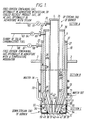
- Figure 1 is a transverse longitudinal cross-section through the upstream and downstream ends of a preferred embodiment of a three-stream burner showing a porous metal cup-shaped cap attached to the downstream end of the burner.
- the present invention pertains to a novel burner for use in the non-catalytic partial oxidation process for the manufacture of synthesis gas, fuel gas, or reducing gas.
- the burner is preferably used with a reactant fuel stream comprising a liquid hydrocarbonaceous fuel or a pumpable slurry of solid carbonaceous fuel in a liquid carrier.
- a reactant feedstream of free-oxygen containing gas with or without admixture with a temperature moderator is mixed with the reactant fuel stream and optionally with a temperature moderator. Atomization and mixing takes place downstream in the reaction zone of a conventional partial oxidation gas generator.
- a hot raw gas stream is produced in the reaction zone of the non-catalytic, refractory-lined, free-flow partial oxidation gas generator at a temperature in the range of 927°C to 1927°C (1700°F to 3500°F) and a pressure in the range of about 0.1 to 304 x 10 -1 MPa (1 to 300 atmospheres), such as 5.1 x 10 -1 to 253 x 10 -1 MPa (5 to 250 atmospheres), say 10.1 x 10 -1 to 101 x 10 -1 MPa (10 to 100 atmospheres).
- a typical partial oxidation gas generator is described in coassigned U.S. Patent No. 2,809,104.
- the effluent raw gas stream from the gas generator comprises H 2 and CO.
- One or more of the following materials are also present: CO 2 , H 2 O, N 2 , A, CH 4 , H 2 S and COS.
- entrained matter e.g. particulate carbon-soot, fly-ash, or slag may be produced along with the raw gas stream.
- the burner comprises a central cylindrical conduit having a central longitudinal axis which is coaxial with that of the gasifier and a converging nozzle that develops into a right cylindrical section of smaller diameter at the downstream end.
- a central cylindrical conduit having a central longitudinal axis which is coaxial with that of the gasifier and a converging nozzle that develops into a right cylindrical section of smaller diameter at the downstream end.
- either 1, 2 or 3 cylindrical conduits are radially spaced and are coaxial and concentric with the central conduit along its length.
- An unobstructed converging exit nozzle is located at the downstream end of the outermost conduit through which a feedstream is discharged.
- the converging portion of the inside surface of the second conduit and the inside and outside surfaces of the central conduit develop into straight cylindrical portions near their downstream ends.
- Conventional separators are used for radially spacing the conduits from each other and forming therebetween, depending on the embodiment, either first, or first and second, or first to fifth unobstructed annular passages.
- alignment pins, fins, centering vanes, spacers and other conventional means are used to symmetrically space the conduits with respect to each other and to hold same in stable alignment with minimal obstruction to the free-flow of the feedstreams.
- first annular passage Near the downstream end of the first annular passage is a converging frusto-conical annular portion that develops into a right cylindrical annular portion. Near the downstream ends of the second and outer annular discharge passages are converging frusto-conical annular portions.
- the conduits and annular passages are closed off at their upstream ends by conventional means that provide a gastight seal e.g. flanges, plates or screw caps.
- a flanged inlet is in communication with the upstream end of each conduit for introducing the following feedstreams: (1) central conduit - a gaseous material comprising free-oxygen containing gas optionally in admixture with a temperature moderator such as H 2 O, or a hydrocarbon gas or a portion of recycle product gas optionally in admixture with a temperature moderator such as H 2 O; (2) second conduit - liquid hydrocarbonaceous fuel optionally in admixture with a temperature moderator e.g.
- the two feedstream burner comprises (1) free-oxygen containing gas with or without admixture with a temperature moderating gas stream such as H 2 O or N 2 passing through the central conduit; and a liquid hydrocarbonaceous fuel optionally in admixture with a temperature moderator e.g. steam and/or an aqueous slurry of solid carbonaceous fuel flowing through the outer annular passage.
- a temperature moderator e.g. steam and/or an aqueous slurry of solid carbonaceous fuel flowing through the outer annular passage.
- the second and outer annular passages converge towards the central longitudinal axis at converging angles in the range of 15° to 60°, such as 20° to 40°.
- the inside diameters of the discharge orifices for the central, first and/or outer conduits are in a horizontal direction successively larger with respect to each other.
- the discharge orifices for the central, first and outer conduits may be located in the same horizontal plane at the tip of the burner or retracted upstream from the horizontal circular exit orifice for the outer conduit, which is at the tip (downstream extremity) of the burner.
- the tips of the central and first, conduits may have 0 vertical retraction with respect to the tip for the outer conduit, or they may be progressively, or non progressively retracted upstream.
- a small amount of mixing may take place in the space located at or just prior to the outer conduit exit orifice. Further, a high bulk velocity of the mixture of slurry of solid carbonaceous fuel and free-oxygen containing gas optionally in admixture with temperature moderator is maintained across the exit orifice of the burner.
- the velocity of the gaseous streams (with or without admixture with a temperature moderator) passing through the central conduit and the outer annular passages of the subject burner is in the range of 6 m/s (20 feet per second) to sonic velocity, say 46 to 229 m/s (150-750 feet per second).
- the velocity of the stream of liquid hydrocarbonaceous fuel or liquid slurry of solid carbonaceous fuel passing through the first annular passage is in the range of 0.3 to 15 m/s (1-50 feet per second), say 3 to 7.6 m/s (10-25 feet per second).
- the velocity of each gaseous stream is at least 17 m/s (56 feet per second) greater than the velocity of the liquid slurry stream.
- All of the free-oxygen containing gas may be split up between two streams, or remain as a single stream, depending upon the embodiment.
- two separate portions of free-oxygen containing gas may be passed through the central conduit and the outer annular passage.
- all of the free-oxygen containing gas may be passed through either the central conduit or the outer annular passage.
- the total flow of the free-oxygen containing gas through the burner may be split between said conduit and passages as follows (in volume %): central conduit - 5 to 60, such as 10 to 20; and outer annular passage - the remainder.
- a selection of the amount of free-oxygen containing gas passing through each conduit or passage is made so that 100% of the flow of free-oxygen containing gas passes through the burner.
- thermal stress cracking of the burner tip is avoided and the operating life of the burner is prolonged.
- a stream of liquid coolant e.g. liquid water or liquid carbon dioxide is used to cool the downstream end of the burner.
- a porous ceramic or porous metal plate or cup is used to shield and cool the downstream end of the burner from the hot hostile environment within the gas generator in the vicinity of the burner tip.
- the burner must withstand contact with recirculating streams of product gas that may comprise mixtures of H 2 , CO, CO 2 , H 2 O, NH 3 , HCOOH, H 2 S, COS, particulate carbon, and ash.
- the temperature in the gasifier may be in the range of 927°C to 1927°C (1700°F to 3500°F). Cooling of the burner tip is achieved by evaporation of the liquid coolant e.g. water that passes through the porous media. In addition some secondary benefit may be achieved by the water flashing off the outer surface of the porous media.
- This steam flow may decrease the potential for ash depositing on the burner face.
- a more uniform and lower temperature level e.g. 149°C to 427°C (300°F to 800°F), say 204°C (400°F) may be achieved at the burner tip, thereby reducing thermal fatigue.
- the amount of liquid water in gallons per minute that is vaporized from the external surface of the porous plate or cup at the burner tip per sq. cm of porous surface area will depend on the size of the process burner used, the geometry of the burner tip, and the heat load to the burner tip.
- a vaporization rate of at least 0.03 dm 3 (0.01 gallons) of water per minute per square cm of porous surface will accommodate a heat load of 791,292 kJ/Hr (750,000 BTU/Hr).
- the thermal efficiency of the process is improved slightly since the water that enters the gasifier is vaporized by heat that would normally be removed from the system by the conventional water cooling and external heat exchange.
- the water that enters the process through the porous media does not effect the mixing or concentration of the slurry at the burner tip and therefore does not effect the efficiency of the combustion of the coal slurry-oxygen mixture.
- a porous ceramic material for making the annular-shaped disc or cup-shaped member that protects the burner tip is hydrophilic and has a particle size in the range of .01 microns to 100 microns, say 0.1 to 40 microns and a uniform porosity in the range of 46.1 to 54.8%, say 48.5 to 52.3%. While alpha-alumina is the preferred porous ceramic, other porous ceramic-like materials that are suitable include gamma alumina, zirconia, silica, titania, and mixtures thereof. Porous metal materials for making the annular-shaped disc or cup-shaped member has a uniform porosity in the range of 46.1 to 54.8%, say 48.5 to 52.3% and include porous stainless steel e.g.
- the porous metal has a particle size in the range of about 0.01 to 100 microns, say 0.1 to 40 microns.
- the wall thickness of the porous plate or cup-shaped member of the burner is in the range of 0.1 to 3 cm, such as 0.3 to 1.0 cm.
- liquid water as the liquid coolant enters and contacts the inside surface of the porous ceramic or porous metal plate or cup at a temperature in the range of 16°C to 49°C (60°F to 120°F). Most of the liquid coolant leaves the burner after contacting the inside surface of the porous plate or porous cup as a liquid at a temperature in the range of 24°C to 57°C (75°F to 135°F).
- the amount of coolant passing through the porous media can be controlled with a conventional pressure control valve on the exit line of the liquid coolant.
- Water passing through the porous media can be measured using a circulating water system and a level controlled water tank wherein fresh pure make-up water will be automatically added in response to a low level resulting from water leaving the system by passing through the porous media (see Figure 1).
- liquid coolant for maximum life of the porous ceramic or porous metal tip cooling means, filtered and demineralized liquid water or purified and distilled water is the preferred liquid coolant.
- liquid carbon dioxide is the liquid coolant. In such case, additional CO will be produced in the partial oxidation gas generator.
- flow control means may be used to start, stop and regulate the flow of the feedstreams to the passages in the burner.
- the feedstreams entering the burner and simultaneously and concurrently passing through at different velocities may be made to impinge and mix with each other just prior to, at, or downstream from the downstream tip of the burner.
- the impingement of one reactant stream such as the liquid slurry of solid carbonaceous fuel in a liquid medium with another reactant stream, such as a gaseous stream of free-oxygen containing gas optionally in admixture with a temperature moderator at a higher velocity, causes the liquid slurry to break up into a fine spray.
- a multiphase mixture is produced in the reaction zone.
- the rate of flow for each of the streams of free-oxygen containing gas is controlled by a flow control valve in each feedline to the burner.
- the rate of flow for the pumpable slurry of solid carbonaceous fuel may be controlled by a speed controlled pump located in the feedline to the burner.
- Turndown or turnup of the burner is effected by changing the rate of flow for each of the streams while maintaining substantially constant the atomic oxygen to carbon ratio and the H 2 O to fuel weight ratio.
- a cylindrical shape slurry stream with the gaseous core that is discharged at the front portion of the burner is impacted by a high velocity stream of free-oxygen containing gas prior to, at, or downstream from the tip of the burner. Efficient atomization of the slurry stream and intimate mixing of the slurry and free-oxygen containing gas streams are thereby assured.
- Burning of the combustible materials while passing through the burner may be prevented by discharging the reactant feedstreams at the central and annular exit orifices at the tip of the burner with a discharge velocity which is greater than the flame propagation velocity.
- Flame speeds are a function of such factors as composition of the mixture, temperature and pressure. They may be calculated by conventional methods or determined experimentally.
- the subject burner assembly is inserted downward through a top inlet port of a compact unpacked free-flow noncatalytic refractory lined synthesis gas generator, for example as shown in coassigned U.S. Patent No. 3,544,291.
- the burner extends along the central longitudinal axis of the gas generator with the downstream end discharging directly into the reaction zone.
- the relative proportions of the reactant feedstreams and optionally temperature moderator that are introduced into the gas generator are carefully regulated to convert a substantial portion of the carbon in the fuel e.g., up to about 98% or more by weight, to carbon oxides; and to maintain an autogenous reaction zone temperature in the range of 927°C to 1927°C (1700° to 3500°F), preferably in the range of 1260°C to 1427°C (2300° to 2600°F).
- the dwell time in the reaction zone is in the range of 1 to 10 seconds, and preferably in the range of 2 to 8.
- the composition of the effluent gas from the gas generator in mole percent dry basis may be as follows: H 2 10 to 60; CO 20 to 60; CO 2 5 to 40; CH 4 0.01 to 5; H 2 S + COS nil to 5; N 2 nil to 5; and A nil to 1.5.
- the composition of the generator effluent gas in mole percent dry basis may be about as follows: H 2 2 to 30; CO 5 to 35; CO 2 5 to 25; CH 4 nil to 2; H 2 S + COS nil to 3; N 2 45 to 80; and A 0.5 to 1.5. Unconverted particulate carbonsoot, ash, slag, or mixtures thereof are contained in the effluent gas stream.
- Pumpable slurries of solid carbonaceous fuels having a dry solids content in the range of 30 to 75 wt.%, say 50 to 70 wt.% may be passed through the inlet passage of the first annular discharge passage.
- the inlet temperature of the slurry is in the range of about ambient to 260°C (500°F), but, preferably below the vaporization temperature of the carrier for the solid carbonaceous fuel at the given inlet pressure in the range of 0.1 to 304 x 10 -1 MPa (1 to 300 atmospheres), such as 5.1 x 10 -1 to 253 x 10 -1 MPa (5 to 250 atmospheres), say 20.2 x 10 -1 to 101 x 10 -1 MPa (20 to 100 atmospheres).
- solid carbonaceous fuels as used herein to describe suitable solid carbonaceous feedstocks, is intended to include various materials and mixtures thereof from the group consisting of coal, coke from coal, char from coal, coal liquefaction residues, petroleum coke, particulate carbon soot, and solids derived from oil shale, tar sands, and pitch. All types of coal may be used including anthracite, bituminous, sub-bituminous, and lignite.
- the particulate carbon soot may be that which is obtained as a byproduct of the subject partial oxidation process, or that which is obtained by burning fossil fuels.
- solid carbonaceous fuel also includes by definition bits of garbage, dewatered sanitary sewage, and semi-solid organic materials such as asphalt, rubber and rubber-like materials including rubber automobile tires.
- the solid carbonaceous fuels are preferably ground to a particle size so that 100% of the material passes through an ASTM E 11-70 Sieve Designation Standard 1.40 mm (Alternative No. 14). Further, in one embodiment, at least 80% passes through an ASTM E 11-70 Sieve Designation Standard 425 mm (Alternative No. 40).
- the moisture content of the solid carbonaceous fuel particles is in the range of 0 to 40 wt.%, such as 2 to 20 wt.%.
- liquid carrier as used herein as the suspending medium to produce pumpable slurries of solid carbonaceous fuels is intended to include various materials from the group consisting of liquid water, liquid hydrocarbonaceous materials, and mixtures thereof.
- liquid water is the preferred carrier for the particles of solid carbonaceous fuel.
- the liquid carrier is liquid carbon dioxide.
- the liquid slurry may comprise 40-70 wt.% of solid carbonaceous fuel and the remainder is liquid CO 2 .
- the CO 2 -solid fuel slurry may be introduced into the burner at a temperature in the range of about -55°C to 38°C (-67°F to 100°F) depending on the pressure.
- free-oxygen containing gas is intended to include air, oxygen-enriched air, i.e., greater than 21 mole percent oxygen, and substantially pure oxygen, i.e. greater than 95 mole percent oxygen, (the remainder comprising N 2 and rare gases).
- a stream of free-oxygen containing gas is supplied to the reaction zone of the gas generator at a temperature in the range of ambient to 816°C (1500°F), and preferably in the range of ambient to 149°C (300°F), for oxygen-enriched air, and 260°C to 816°C (500° to 1500°F), for air.
- the pressure in the partial oxidation reaction zone is in the range of 0.1 to 304 x 10 -1 MPa (1 to 300 atmospheres) such as 5.1 x 10 -1 to 253 x 10 -1 MPa (5 to 250 atmospheres), say 20.2 x 10 -1 to 101 x 10 -1 MPa (20 to 100 atmospheres).
- the atoms of free-oxygen plus atoms of organically combined oxygen in the solid carbonaceous fuel per atom of carbon in the solid carbonaceous fuel (O/C atomic ratio) may be in the range of 0.5 to 1.95.
- temperature moderator as employed herein includes water, steam, CO 2 , N 2 , and a cooled recycle portion of the product gas stream.
- the temperature moderator may be in admixture with the fuel stream and/or the oxidant stream. However, if a cooled recycle portion of the product gas stream is used it cannot be in admixture with the oxidant stream.
- hydrocarbon gas as used herein includes methane, ethane, propane, butane, and natural gas.
- the feedstream comprises a slurry of liquid hydrocarbonaceous material and solid carbonaceous fuel; H 2 O in liquid phase may be mixed with the liquid hydrocarbonaceous carrier, for example as an emulsion. A portion of the H 2 O i.e., 0 to 25 wt.% of the total amount of H 2 O present may be introduced as steam in admixture with the free-oxygen containing gas.
- the weight ratio of H 2 O/fuel may be in the range of 0 to 5, say 0.1 to 3.
- liquid hydrocarbonaceous fuel as used herein is intended to include various materials, such as liquefied petroleum gas, petroleum distillates and residues, gasoline, naphtha, kerosine, crude petroleum, asphalt, gas oil, residual oil, tar sand oil and shale oil, coal derived oil, aromatic hydrocarbon (such as benzene, toluene, xylene fractions), coal tar, cycle gas oil from fluid-catalytic-cracking operation, furfural extract of coker gas oil, methanol, ethanol and other alcohols and by-product oxygen containing liquid hydrocarbons from oxo or oxyl synthesis, and mixtures thereof.
- materials such as liquefied petroleum gas, petroleum distillates and residues, gasoline, naphtha, kerosine, crude petroleum, asphalt, gas oil, residual oil, tar sand oil and shale oil, coal derived oil, aromatic hydrocarbon (such as benzene, toluene, xylene fractions), coal tar, cycle gas
- FIG. 1 a preferred three-stream burner assembly is depicted.
- This embodiment shall be referred to herein as embodiment A of Figure 1.
- a three-stream burner accommodates, simultaneously, three separate feedstreams.
- Burner 1 is installed with the downstream end passing downwardly through a port in the top of a free-flow partial oxidation synthesis gas generator (not shown).
- the longitudinal central axis of burner 1 is preferably aligned along the central axis of the synthesis gas generator by means of mounting flange 3.
- Burner 1 comprises central, second, and outer concentric cylindrically shaped conduits 8, 9 and 10 respectively.
- a porous metal coaxial water-cooled tip cup 12 is located at the downstream extremity of the burner.
- External cooling coils 13 may encircle the downstream portion of burner 1.
- Flanged inlet pipes 20-22 for the feedstreams to the burner are connected to central conduit 8, and concentric, hollow, cylindrical conduits 9 and 10 respectively.
- the burner has two unobstructed annular passages for the free-flow of the feedstreams.
- the annular passages are formed by radially spacing the three conduits.
- first annular passage 25 is located between the outside diameter of central conduit 8 and the inside diameter of second conduit 9.
- the radial spacing between the central and second conduits is maintained by wall spacers 26.
- Outer annular passage 27 is located between the outside diameter of second conduit 9 and the inside diameter of outer conduit 10.
- Wall spacers 28 maintain the radial spacing between the second and third conduits.
- each conduit and annular passage is closed off.
- Cover plates 35 to 37 seal off the upstream ends of central conduit 8, annular passage 25 and outer annular passage 27, respectively.
- Conventional means may be used to secure the cover plate to the ends of the conduit e.g., flanging, welding, threading. Gasketing may be used to provide a leak-proof seal.
- the outside diameter of central conduit 8 and the inside diameter of second conduit 9 are gradually reduced, for example 30-50%, and develop into right cylindrical portions 40 and 41, respectively.
- Right annular passage 42 is located between right cylindrical portions 40 and 41. Tips 44 and optionally 43 of second conduit 9 and central conduit 8, respectively may be progressively retracted upstream from the face of the burner to provide a diverging frusto-conical area 47, as shown in the drawing.
- tips 43, and 44 may terminate in the same horizontal plane perpendicular to the central longitudinal axis of the burner at the downstream face of the burner.
- the foremost portion of cooling chamber 12 terminates in the same perpendicular plane at the face 46 of the burner.
- outer conduit 10 divides into two branched walls 50 and 51.
- Branch 50 is frusto-conical shaped, and converges towards the downstream face of the burner.
- the inside surface of branch wall 50 is separated from the outside surface of the downstream converging portion 52 of second conduit 9 by separating means 28 thereby forming the downstream discharge portion 53 of outer annular passage 27.
- Porous cup 12 is joined to the tip of burner 1 by welding, brazing, bolting, cementing, or other suitable means so as to provide a hollow leak-proof annular-shaped liquid coolant chamber 54.
- the upper end of the side wall of porous metal cup 12 is circumferentially welded or otherwise joined to the end of branch 51 of outer conduit 10. Joint 55 is cooled and protected by its proximity to liquid coolant pipes 70 and 71.
- the inside bottom surface 59 of porous cup 12 is circumferentially welded or otherwise sealed around hole 57 to the end of branch wall 50 at point 56.
- Embodiment B of Figure 1 is substantially the same as embodiment A but with the exception that joint 56 is retracted upstream from burner face 46 so as to protect the joint from the hot swirling gases at the burner face.
- the bottom porous metal wall of tip cup 12 abruptly changes direction at central hole 57 and proceeds in an upward direction to a circumferential joint located at 58.
- a short frusto-conical shaped porous lip section is thereby formed having a height equal to 1/4 to 1/2 of the diameter of central hole 57 at the face of the burner.
- the upstream end of the porous metal lip section is circumferentially welded to the downstream end of frusto-conical shaped wall 50 to provide a leak-proof seal.
- the diameter of coaxial hole 57 at the bottom of porous cup 12 permits the free discharge of all of the feedstreams from all of the feedstream passages in the burner.
- a gaseous material comprising free-oxygen containing gas optionally in admixture with a temperature moderator such as H 2 O, or a hydrocarbon gas or a portion of recycle product gas optionally in admixture with a temperature moderator such as H 2 O is passed through line 60, flow control valve 61, line 62, and inlet pipe 20.
- a pumpable liquid phase slurry of solid carbonaceous fuel for example a coal-water slurry, is passed through line 63, flow control means 64, line 65, and inlet pipe 21.
- a separate stream of free-oxygen containing gas optionally in admixture with a temperature moderator is passed through line 66, flow control valve 67, line 68, and inlet pipe 22.
- a liquid coolant e.g. water is supplied to annular-shaped liquid coolant chamber 54 by way of line 70.
- the liquid coolant flows through chamber 54 under pressure so that a portion of the liquid coolant flows out through the porous bottom wall and side walls of tip cup 12.
- the water passing through the walls of cup 12 and on the external surfaces of cup 12 absorbs heat from the cup 12 and is converted to steam thereby cooling the tip of the burner. Additional heat is picked up by conduction as the liquid coolant passes in and out of chamber 54.
- the liquid coolant leaves coolant chamber 54 through line 71 and is passed through coil 13 which encircles the outside diameter of the burner.
- liquid coolant enters coolant chamber 54 by both lines 70 and 71.
- Embodiment C (not shown) is substantially the same as embodiment A or B of Figure 1 except for a flat porous ceramic or porous metal annular-shaped disc which replaces tip cup 12.
- branch wall 51 may continue to the end of the burner where it is welded or otherwise attached, for example by bolting with gaskets to provide a leak-proof seal to a flat porous ceramic disc.
- the end of branch wall 50 may be similarly attached to the flat porous disc.
- the end of branch wall 50 maybe welded to the top surface and/or inside edge of central hole 57 or the end of the upward extension at 58 of a porous metal tip cooling member.
- the burner is adapted to introduce only two feedstreams.
- second conduit 9, converging portion 52, and inlet 21 are eliminated from the burner shown in Figure 1.
- a stream of free-oxygen containing gas optionally in admixture with a temperature moderating gas, e.g. steam is passed through either inlet nozzle 20 or inlet nozzle 22.
- a stream of liquid fuel e.g. liquid hydrocarbonaceous fuel optionally in admixture with a temperature moderator e.g. steam, or an aqueous slurry of solid carbonaceous fuel is passed through the remaining free passage.
Landscapes
- Chemical & Material Sciences (AREA)
- Engineering & Computer Science (AREA)
- Combustion & Propulsion (AREA)
- Organic Chemistry (AREA)
- Chemical Kinetics & Catalysis (AREA)
- Health & Medical Sciences (AREA)
- General Health & Medical Sciences (AREA)
- Inorganic Chemistry (AREA)
- Oil, Petroleum & Natural Gas (AREA)
- Mechanical Engineering (AREA)
- General Engineering & Computer Science (AREA)
Claims (12)
- Brûleur pour l'oxydation partielle d'un courant de combustible de réactant, comprenant un combustible hydrocarboné liquide ou une suspension pompable de combustible carboné solide dans un agent vecteur liquide, comprenant un conduit central et au moins un conduit coaxial concentrique placé à une certaine distance, avec un passage annulaire à écoulement vers le bas, entre lesdits conduits, lesdits conduit et passage annulaire étant fermés à leurs extrémités en amont et ouverts à leurs extrémités en aval; des moyens d'entrée raccordés à l'extrémité en amont desdits conduit et passage pour le passage d'un courant d'alimentation de réactant ou de réfrigérant liquide; une buse coaxiale concentrique terminant l'extrémité en aval desdits conduit et passage; caractérisé par un moyen de refroidissement en céramique poreuse ou en métal poreux, attaché à l'extrémité en aval dudit brûleur; des moyens d'alimentation et d'évacuation du réfrigérant liquide en communication fluide avec lesdits moyens de refroidissement poreux; caractérisé en ce que ledit moyen de refroidissement poreux comprend un matériau poreux de composition, d'épaisseur de paroi et de porosité uniformes, y compris des surfaces internes et externes poreuses et un noyau poreux avec les différents pores en état d'interconnexion; ce grâce à quoi le débit dudit réfrigérant liquide à travers lesdits moyens de refroidissement de bout poreux peut être contrôlé et caractérisé en ce que ledit moyen de refroidissement de bout contient un trou central pour le passage libre desdits courants d'alimentation de réactants dans la zone de réaction; ce grâce à quoi au moins une portion dudit réfrigéant liquide sous pression passe successivement à travers la surface interne poreuse, le noyau poreux et la surface externe poreuse dudit moyen de refroidissement poreux et se vaporise, en refroidissant ainsi le bout dudit brûleur.
- Brûleur selon la revendication 1, caractérisé en ce que ledit moyen de refroidissement poreux a la forme d'une coupelle ou la forme d'un disque annulaire plat.
- Brûleur selon la revendication 1 ou la revendication 2, caractérisé en ce que ledit moyen de refroidissement poreux est fait d'un matériau en céramique poreuse choisi parmi le groupe se composant de l'alumine alpha, de l'alumine gamma, de la zircone, de la silice, de l'oxyde de titane et de leurs mélanges.
- Brûleur selon la revendication 1 ou la revendication 2, caractérisé en ce que ledit moyen de refroidissement poreux est fait d'un métal poreux choisi parmi le groupe se composant d'acier inoxydable poreux, d'alliages de nickel tels que les alliages Inconel et Incoloy, et d'alliages de cobalt tels que l'alliage UMCO 50.
- Brûleur selon l'une quelconque des revendications 2 - 4, caractérisé en ce que ledit moyen de refroidissement en métal poreux a une porosité uniforme dans le domaine d'environ 46,1 à 54,8 % et une épaisseur d'environ de 0,1 à 3 cm.
- Brûleur selon l'une quelconque des revendications 1 - 5, pourvu de moyens pour alimenter ledit réfrigérant à un différentiel de pression positif dans le domaine d'environ 0,07 x 10⁻¹ à 42 x 10-1 MPa (1 à 600 livres par pouce carré) pour forcer le réfrigérant liquide à travers les milieux poreux.
- Brûleur selon l'une quelconque des revendications 1 à 6, pour l'introduction simultanée d'un courant de gaz contenant de l'oxygène libre et d'un courant de combustible pompable vers le bas dans la zone de réaction d'un générateur à gaz par oxydation partielle à écoulement libre, caractérisé en ce que ledit conduit central est formé de manière cylindrique et a un axe longitudinal central qui est coaxial par rapport à l'axe longitudinal central du brûleur; une buse de sortie convergente non obstruée qui se transforme en une portion cylindrique rectiligne avec un orifice de sortie circulaire à l'extrémité en aval du conduit central et des moyens de fermeture attachés à l'extrémité en amont dudit conduit central pour la fermeture de celui-ci; caractérisé en ce qu'au moins un conduit coaxial concentrique placé à une certaine distance comprend un deuxième conduit, coaxial et concentrique par rapport audit conduit central le long de sa longueur, une buse de sortie convergente qui se transforme en une portion cylindrique rectiligne avec un orifice de sortie circulaire à l'extrémité en aval du deuxième conduit; des moyens pour l'espacement radial dudit conduit central et dudit deuxième conduit, et pour la formation, entre les deux, d'un premier passage annulaire qui se transforme en un passage annulaire droit près de l'extrémité en aval; et des moyens de fermetures attachés audit deuxième conduit et premier passage annulaire à leurs extrémités en amont pour la fermeture de ceux-ci, ledit conduit central passant à travers l'extrémité fermée en amont dudit deuxième conduit et réalisant ainsi un joint étanche aux gaz; et un conduit externe, coaxial et concentrique par rapport audit deuxième conduit le long de sa longueur, des moyens pour l'espacement radial dudit deuxième conduit et dudit conduit externe, et pour la formation, entre eux, d'un deuxième passage annulaire qui se transforme en une portion convergente en forme de tronc de cône vers l'extrémité en aval; et des moyens de fermeture attachés au deuxième passage annulaire et au conduit externe à leurs extrémités en amont pour le fermeture de ceux-ci, ledit deuxième conduit passant à travers l'extrémité fermée en amont du conduit externe et réalisant ainsi un joint étanche aux gaz; caractérisé en ce que des conduits de courant d'alimentation séparés sont raccordés extérieurement auxdits moyens d'entrée à chacun desdits éléments conduit central, deuxième conduit et conduit externe; et que des moyens de contrôle du débit sont prévus dans chacun desdits conduits de courant d'alimentation pour le contrôle séparé du débit du courant d'alimentation passant à travers lesdits conduits de courant d'alimentation; des moyens de fixation par brides étant attachés à la surface externe dudit conduit externe pour l'alignement de l'axe longitudinal central dudit brûleur le long de l'axe central du générateur à gaz, alors que l'extrémité en aval dudit brûleur passe vers le bas à travers un orifice dans le haut du générateur à gaz; et ledits moyens de refroidissement en céramique poreuse ou en métal poreux étant attachés au bout dudit brûleur et formant une chambre creuse, de forme annulaire, à réfrigérant liquide; caractérisé en ce que les bouts dudit conduit central et/ou dudit deuxième conduit soit sont rétractés en amont de l'orifice de sortie du conduit externe, soit se terminent dans le même plan que l'orifice de sortie du conduit externe, perpendiculaire à l'axe longitudinal du brûleur, pour fournir, en cours d'utilisation, un courant de suspension de forme cylindrique avec un noyau gazeux qui passe à travers la portion avant du brûleur et qui est soumis à un impact par un courant à haute vitesse de gaz contenant de l'oxygène libre, en mélange facultativement avec un agent modérateur de la température, et que ledit impact a lieu avant, au, ou en aval du bout du brûleur pour fournir une atomisation et un mélange intime de l'alimentation de suspension avec le gaz contenant de l'oxygène libre.
- Brûleur selon la revendication 7, caractérisé en ce que ledit moyen de refroidissement poreux est un métal poreux et a la forme d'une coupelle avec un trou central coaxial dans le fond pour permettre la décharge desdits courants d'alimentation; que la paroi dudit conduit externe se transforme en une paroi de dérivation verticale et une paroi de dérivation convergente à l'extrémité en aval du brûleur; et que ledit moyen de refroidissement poreux en forme de coupelle est attaché au bout dudit brûleur par soudage de l'extrémité en amont de la paroi verticale de ladite coupelle de bout poreuse à l'extrémité en aval de ladite paroi de dérivation verticale dudit conduit externe, et par soudage du fond de la coupelle de bout ou par soudage du haut d'une portion, se prolongeant vers le haut, du fond de la coupelle de bout poreuse entourant le trou central à l'extrémité en aval de ladite paroi de dérivation convergente dudit conduit externe, en fournissant ainsi au bout du brûleur une chambre poreuse de forme annulaire pour le réfrigérant liquide.
- Brûleur selon la revendication 7 ou la revendication 8, caractérisé en ce que les bouts du conduit central et du deuxième conduit sont rétractés progressivement en amont de la paroi d'orifice de sortie du conduit externe, de manière à fournir une zone de décharge divergente en forme de tronc de cône avant le bout en aval du brûleur.
- Brûleur selon la revendication 8 ou la revendication 9, en cas de dépendance vis-à-vis de la revendication 8, pourvu d'un tuyau d'entrée pour l'introduction dudit réfrigérant liquide dans l'extrémité supérieure de ladite chambre poreuse de forme annulaire; pourvu d'un tuyau de sortie pour l'élimination dudit réfrigérant liquide en provenance de ladite chambre poreuse de forme annulaire, et pour le refroidissement de bobines encerclant l'extrémité en aval dudit brûleur et raccordés audit tuyau d'évacuation du réfrigérant liquide.
- Brûleur selon l'une quelconque des revendications 1 - 6, pour l'introduction simultanée d'un courant de gaz contenant de l'oxygène libre et d'un courant de combustible pompable vers le bas en direction de la zone de réaction d'un générateur à gaz par oxydation partielle à écoulement libre, caractérisé en ce que ledit conduit central est formé de manière cylindrique et a un axe longitudinal central qui est coaxial par rapport à l'axe longitudinal central du brûleur; une buse de sortie convergente non obstruée qui se transforme en une portion cylindrique rectiligne avec un orifice de sortie circulaire à l'extrémité en aval du conduit central et des moyens de fermeture attachés à l'extrémité en amont dudit conduit central pour la fermeture de celui-ci; caractérisé en ce qu'au moins un dit conduit coaxial concentrique placé à une certaine distance comprend un conduit externe, coaxial et concentrique par rapport audit conduit central le long de sa longueur, une buse de sortie convergente qui se transforme en une section en forme de tronc de cône à l'extrémité en aval dudit conduit externe; des moyens pour l'espacement radial dudit conduit central et dudit conduit externe, et pour la formation, entre les deux, d'un premier passage annulaire; des moyens de fermetures attachés audit conduit externe et audit premier passage annulaire à leurs extrémités en amont pour le fermeture de ceux-ci, ledit conduit central passant à travers l'extrémité fermée en amont dudit conduit externe et réalisant ainsi un joint étanche aux gaz; un conduit de courant d'alimentation séparé raccordé extérieurement audit moyen d'entrée dudit conduit et dudit passage, respectivement avec des moyens de contrôle de l'écoulement dans chacun dudit conduit de courant d'alimentation pour le contrôle séparé du débit du courant d'alimentation passant à travers ledit conduit de courant d'alimentation; et des moyens de fixation par brides attachés à la surface externe dudit conduit externe pour l'alignement de l'axe longitudinal central dudit brûleur le long de l'axe central du générateur à gaz, alors que l'extrémité en aval dudit brûleur passe vers le bas à travers un orifice dans le haut du générateur à gaz; ledits moyens de refroidissement en céramique poreuse ou en métal poreux contrôlant le débit d'une portion dudit réfrigérant liquide y passant à travers et formant une chambre creuse, de forme annulaire, à réfrigérant liquide; caractérisé en ce que le bout dudit conduit central est, soit rétracté en amont de l'orifice de sortie du conduit externe, soit se termine avec l'orifice de sortie du conduit externe dans le même plan perpendiculaire à l'axe longitudinal du brûleur; et caractérisé en ce que lesdits courants d'alimentation, en cours d'utilisation, sont soumis à un impact mutuel avant, au, ou en aval du bout du brûleur, pour fournir un combustible atomisé et intimement mélangé.
- Brûleur selon la revendication 11, caractérisé en ce que ledit moyen de refroidissement poreux a la forme d'une coupelle; et que ledit moyen de refroidissement poreux est attaché au bout dudit brûleur de manière à fournir une chambre de forme annulaire, étanche aux fuites pour ledit réfrigérant liquide.
Priority Applications (3)
| Application Number | Priority Date | Filing Date | Title |
|---|---|---|---|
| US07/812,310 US5261602A (en) | 1991-12-23 | 1991-12-23 | Partial oxidation process and burner with porous tip |
| DE1993619906 DE69319906T2 (de) | 1993-08-31 | 1993-08-31 | Partialoxydationsverfahren und Brennen mit porösem Mundstück |
| EP93306867A EP0640679B1 (fr) | 1991-12-23 | 1993-08-31 | Procédé d'oxydation partielle et brûleur avec paroi frontale poreuse |
Applications Claiming Priority (2)
| Application Number | Priority Date | Filing Date | Title |
|---|---|---|---|
| US07/812,310 US5261602A (en) | 1991-12-23 | 1991-12-23 | Partial oxidation process and burner with porous tip |
| EP93306867A EP0640679B1 (fr) | 1991-12-23 | 1993-08-31 | Procédé d'oxydation partielle et brûleur avec paroi frontale poreuse |
Publications (2)
| Publication Number | Publication Date |
|---|---|
| EP0640679A1 EP0640679A1 (fr) | 1995-03-01 |
| EP0640679B1 true EP0640679B1 (fr) | 1998-07-22 |
Family
ID=26134433
Family Applications (1)
| Application Number | Title | Priority Date | Filing Date |
|---|---|---|---|
| EP93306867A Expired - Lifetime EP0640679B1 (fr) | 1991-12-23 | 1993-08-31 | Procédé d'oxydation partielle et brûleur avec paroi frontale poreuse |
Country Status (2)
| Country | Link |
|---|---|
| US (1) | US5261602A (fr) |
| EP (1) | EP0640679B1 (fr) |
Families Citing this family (62)
| Publication number | Priority date | Publication date | Assignee | Title |
|---|---|---|---|---|
| US5261602A (en) * | 1991-12-23 | 1993-11-16 | Texaco Inc. | Partial oxidation process and burner with porous tip |
| US5515794A (en) | 1995-01-23 | 1996-05-14 | Texaco Inc. | Partial oxidation process burner with recessed tip and gas blasting |
| US5934206A (en) * | 1997-04-07 | 1999-08-10 | Eastman Chemical Company | High temperature material face segments for burner nozzle secured by brazing |
| MXPA02010663A (es) | 2000-04-30 | 2003-06-25 | Casale Chemicals Sa | Quemador. |
| CN1260001C (zh) * | 2000-05-05 | 2006-06-21 | 陶氏环球技术公司 | 用于卤代物质的气化反应器的进料喷嘴 |
| US6755355B2 (en) | 2002-04-18 | 2004-06-29 | Eastman Chemical Company | Coal gasification feed injector shield with integral corrosion barrier |
| US6892654B2 (en) * | 2002-04-18 | 2005-05-17 | Eastman Chemical Company | Coal gasification feed injector shield with oxidation-resistant insert |
| US7117675B2 (en) | 2002-12-03 | 2006-10-10 | General Electric Company | Cooling of liquid fuel components to eliminate coking |
| US6918255B2 (en) * | 2002-12-03 | 2005-07-19 | General Electric Company | Cooling of liquid fuel components to eliminate coking |
| US8449288B2 (en) * | 2003-03-19 | 2013-05-28 | Nalco Mobotec, Inc. | Urea-based mixing process for increasing combustion efficiency and reduction of nitrogen oxides (NOx) |
| US8353698B2 (en) * | 2003-06-13 | 2013-01-15 | Nalco Mobotec, Inc. | Co-axial injection system |
| US7670569B2 (en) * | 2003-06-13 | 2010-03-02 | Mobotec Usa, Inc. | Combustion furnace humidification devices, systems & methods |
| US8251694B2 (en) * | 2004-02-14 | 2012-08-28 | Nalco Mobotec, Inc. | Method for in-furnace reduction flue gas acidity |
| US7537743B2 (en) * | 2004-02-14 | 2009-05-26 | Mobotec Usa, Inc. | Method for in-furnace regulation of SO3 in catalytic NOx reducing systems |
| US7198555B2 (en) * | 2004-12-30 | 2007-04-03 | Southwest Research Institute | Atomizer cooling by liquid circulation through atomizer tip holder |
| PL204019B1 (pl) * | 2005-06-05 | 2009-12-31 | Telesto Spo & Lstrok Ka Z Ogra | Urządzenie do gaszenia pożarów i głowica gasząca |
| US7410356B2 (en) | 2005-11-17 | 2008-08-12 | Mobotec Usa, Inc. | Circulating fluidized bed boiler having improved reactant utilization |
| KR100805630B1 (ko) * | 2006-12-01 | 2008-02-20 | 주식회사 경동나비엔 | 가스보일러의 연소장치 |
| DE102007021926A1 (de) * | 2007-05-10 | 2008-11-20 | Siemens Ag | Öl-/Slurrybrenner mit Injektionszerstäubung |
| US7993131B2 (en) * | 2007-08-28 | 2011-08-09 | Conocophillips Company | Burner nozzle |
| DE102007040890A1 (de) * | 2007-08-29 | 2009-03-05 | Siemens Ag | Kohlenstaubkombinationsbrenner mit integriertem Pilotbrenner |
| US7775791B2 (en) * | 2008-02-25 | 2010-08-17 | General Electric Company | Method and apparatus for staged combustion of air and fuel |
| US9657989B2 (en) | 2008-04-07 | 2017-05-23 | Wastedry, Llc | Systems and methods for processing municipal wastewater treatment sewage sludge |
| US9638414B2 (en) * | 2008-04-07 | 2017-05-02 | Wastedry Llc | Systems and methods for processing municipal wastewater treatment sewage sludge |
| US7832341B2 (en) * | 2008-04-30 | 2010-11-16 | Walsh Jr William Arthur | Merging combustion of biomass and fossil fuels in boilers |
| US8069824B2 (en) | 2008-06-19 | 2011-12-06 | Nalco Mobotec, Inc. | Circulating fluidized bed boiler and method of operation |
| US8580001B2 (en) * | 2008-08-21 | 2013-11-12 | General Electric Company | Method and apparatus for assembling gasification reactor injection devices |
| EP2326878A2 (fr) * | 2008-09-26 | 2011-06-01 | Air Products and Chemicals, Inc. | Systeme de combustion a element de precombustion pour gaz de combustion recycle |
| US8177145B2 (en) | 2008-11-04 | 2012-05-15 | General Electric Company | Feed injector system |
| FR2941286B1 (fr) * | 2009-01-16 | 2012-08-31 | Air Liquide | Bruleur pilote air-gaz pouvant fonctionner a l'oxygene. |
| US20100281872A1 (en) * | 2009-05-06 | 2010-11-11 | Mark Allan Hadley | Airblown Syngas Fuel Nozzle With Diluent Openings |
| US20100281869A1 (en) * | 2009-05-06 | 2010-11-11 | Mark Allan Hadley | Airblown Syngas Fuel Nozzle With Diluent Openings |
| US8607570B2 (en) * | 2009-05-06 | 2013-12-17 | General Electric Company | Airblown syngas fuel nozzle with diluent openings |
| EP2275741A1 (fr) * | 2009-07-14 | 2011-01-19 | Siemens AG | Buse et procédé de fabrication d'une buse |
| CN101650031B (zh) * | 2009-09-18 | 2011-04-13 | 兖矿集团有限公司 | 一种用于水煤浆或煤粉气化炉的开工复合烧嘴 |
| CN101691924B (zh) * | 2009-10-21 | 2011-08-17 | 北京航天动力研究所 | 自带点火装置的水煤浆加压气化工艺烧嘴装置 |
| KR101096632B1 (ko) | 2009-12-10 | 2011-12-21 | 에스케이이노베이션 주식회사 | 상부 공급 이중선회형 가스화기 |
| DE102010004787B4 (de) | 2010-01-16 | 2014-02-13 | Lurgi Gmbh | Verfahren und Brenner zur Herstellung von Synthesegas |
| US8360342B2 (en) | 2010-04-30 | 2013-01-29 | General Electric Company | Fuel injector having differential tip cooling system and method |
| US9079199B2 (en) * | 2010-06-14 | 2015-07-14 | General Electric Company | System for increasing the life of fuel injectors |
| CN101956982A (zh) * | 2010-09-19 | 2011-01-26 | 昆明理工大学 | 一种气化炉用耐高温烧嘴 |
| US8960108B1 (en) | 2010-12-20 | 2015-02-24 | SilverStreet Group, LLC | System and method for cogeneration from mixed oil and inert solids, furnace and fuel nozzle for the same |
| DE102011008187B4 (de) * | 2011-01-10 | 2015-08-27 | Suncoal Industries Gmbh | Verfahren zur Erzeugung von Brenn- und Syntheserohgas |
| CN102935675A (zh) * | 2011-08-16 | 2013-02-20 | 深圳富泰宏精密工业有限公司 | 模具 |
| DE102012217718A1 (de) | 2011-09-30 | 2013-04-04 | Diehl Bgt Defence Gmbh & Co. Kg | Pyrotechnische Kaltgasgeneratoren |
| CN103175202A (zh) * | 2011-12-20 | 2013-06-26 | 西安航天远征流体控制股份有限公司 | 非预混式开工烧嘴 |
| DE102012016086A1 (de) * | 2012-08-14 | 2014-02-20 | Thyssenkrupp Uhde Gmbh | Vorrichtung und Verfahren zur Eindüsung von Sauerstoff in eine druckaufgeladene Wirbelschichtvergasung |
| CN102851091B (zh) * | 2012-10-08 | 2014-05-21 | 黑龙江北大荒农业股份有限公司浩良河化肥分公司 | 适用于德士古加压水煤浆气化炉用煤 |
| JP5968247B2 (ja) * | 2013-02-08 | 2016-08-10 | 三菱日立パワーシステムズ株式会社 | バーナおよび燃焼炉ならびにバーナの組立方法およびバーナの補修方法 |
| US9709271B2 (en) * | 2013-02-20 | 2017-07-18 | Fluor Technologies Corporation | Thermally controlled combustion system |
| US10138151B2 (en) * | 2013-05-22 | 2018-11-27 | Johns Manville | Submerged combustion burners and melters, and methods of use |
| WO2014189499A1 (fr) * | 2013-05-22 | 2014-11-27 | Johns Manville | Brûleurs et appareils de fusion à combustion immergés, et procédés d'utilisation |
| US10183884B2 (en) * | 2013-05-30 | 2019-01-22 | Johns Manville | Submerged combustion burners, submerged combustion glass melters including the burners, and methods of use |
| CN104566365B (zh) * | 2013-10-15 | 2017-02-15 | 张旭 | 一种燃烧器及火焰温度控制方法 |
| DE102014211757B4 (de) | 2014-06-18 | 2018-05-30 | Technische Universität Bergakademie Freiberg | Brennervorrichtung für die Partialoxidation von gasförmigen Vergasungsstoffen |
| AU2016214506B2 (en) * | 2015-02-05 | 2021-04-08 | Casale Sa | Burner for the production of synthesis gas and related cooling circuit |
| JP6716422B2 (ja) * | 2016-10-21 | 2020-07-01 | 三菱日立パワーシステムズ株式会社 | バーナ装置、バーナ装置の冷却管破損検出方法、およびバーナ装置の冷却媒体制御方法 |
| DE202018101400U1 (de) * | 2017-05-11 | 2018-04-12 | L'Air Liquide Société Anonyme pour l'Etude et l'Exploitation des Procédés Georges Claude | Brenner zur Synthesegaserzeugung |
| KR102325814B1 (ko) * | 2019-08-21 | 2021-11-11 | 씨에스케이(주) | 스크러버용 버너 |
| CN114015477A (zh) * | 2021-09-13 | 2022-02-08 | 郑州大学 | 一种四通道工艺烧嘴 |
| US12215861B2 (en) * | 2021-12-13 | 2025-02-04 | Owens-Brockway Glass Container Inc. | Heat pipe for submerged combustion burner |
| EP4310394B1 (fr) | 2022-07-21 | 2025-05-21 | L'air Liquide, Société Anonyme Pour L'Étude Et L'exploitation Des Procédés Georges Claude | Agencement de brûleur pour la production de gaz de synthèse |
Family Cites Families (25)
| Publication number | Priority date | Publication date | Assignee | Title |
|---|---|---|---|---|
| US3528930A (en) * | 1968-05-29 | 1970-09-15 | Texaco Inc | Production of synthesis gas |
| US3847564A (en) * | 1970-01-23 | 1974-11-12 | Texaco Development Corp | Apparatus and process for burning liquid hydrocarbons in a synthesis gas generator |
| US3758037A (en) * | 1971-10-04 | 1973-09-11 | Texaco Development Corp | Fuel burner and process for gas manufacture |
| JPS4917306A (fr) * | 1972-06-13 | 1974-02-15 | ||
| US4007019A (en) * | 1975-12-22 | 1977-02-08 | Texaco Inc. | Production of clean synthesis or fuel gas |
| DE2703921C3 (de) * | 1977-01-31 | 1980-09-11 | Basf Ag, 6700 Ludwigshafen | Verfahren zur Inbetriebnahme oder Herstellung der Betriebsbereitschaft eines Reaktors für die partielle Oxidation von schwerflüchtigen flüssigen oder festen Brennstoffen |
| NL7704399A (nl) * | 1977-04-22 | 1978-10-24 | Shell Int Research | Werkwijze en reactor voor de partiele ver- branding van koolpoeder. |
| US4222434A (en) * | 1978-04-27 | 1980-09-16 | Clyde Robert A | Ceramic sponge heat-exchanger member |
| DE3219316A1 (de) * | 1982-05-22 | 1983-11-24 | Ruhrchemie Ag, 4200 Oberhausen | Verfahren und vorrichtung zur herstellung von synthesegas durch partielle oxidation von kohle-wasser-suspensionen |
| US4502633A (en) * | 1982-11-05 | 1985-03-05 | Eastman Kodak Company | Variable capacity gasification burner |
| JPS5993181A (ja) * | 1982-11-19 | 1984-05-29 | Hitachi Ltd | 液膜蒸発式熱交換器 |
| GB8307519D0 (en) * | 1983-03-18 | 1983-04-27 | Shell Int Research | Burner |
| US4525175A (en) * | 1983-05-31 | 1985-06-25 | Texaco Inc. | High turn down burner for partial oxidation of slurries of solid fuel |
| US4443230A (en) * | 1983-05-31 | 1984-04-17 | Texaco Inc. | Partial oxidation process for slurries of solid fuel |
| US4525176A (en) * | 1983-08-29 | 1985-06-25 | Texaco Inc. | Preheating and deslagging a gasifier |
| JPS60152895A (ja) * | 1984-01-19 | 1985-08-12 | Daido Steel Co Ltd | 伝熱変換体 |
| JPS6183897A (ja) * | 1984-09-28 | 1986-04-28 | Asahi Glass Co Ltd | セラミツクス製の熱交換体 |
| IN167217B (fr) * | 1985-04-16 | 1990-09-22 | Dow Chemical Co | |
| US4775314A (en) * | 1985-05-20 | 1988-10-04 | Shell Oil Company | Coal gasification burner |
| US4644878A (en) * | 1985-11-05 | 1987-02-24 | The United States Of America As Represented By The United States Department Of Energy | Slurry burner for mixture of carbonaceous material and water |
| DD251476A3 (de) * | 1985-11-12 | 1987-11-18 | Freiberg Brennstoffinst | Kohlenstaubbrenner |
| US4736693A (en) * | 1987-07-31 | 1988-04-12 | Shell Oil Company | Partial combustion burner with heat pipe-cooled face |
| US4952218A (en) * | 1988-08-26 | 1990-08-28 | The Dow Chemical Company | Two-fluid nozzle for atomizing a liquid solid slurry and protecting nozzle tip |
| DE4140063A1 (de) * | 1991-12-05 | 1993-06-09 | Hoechst Ag, 6230 Frankfurt, De | Brenner zur herstellung von synthesegas |
| US5261602A (en) * | 1991-12-23 | 1993-11-16 | Texaco Inc. | Partial oxidation process and burner with porous tip |
-
1991
- 1991-12-23 US US07/812,310 patent/US5261602A/en not_active Expired - Fee Related
-
1993
- 1993-08-31 EP EP93306867A patent/EP0640679B1/fr not_active Expired - Lifetime
Also Published As
| Publication number | Publication date |
|---|---|
| EP0640679A1 (fr) | 1995-03-01 |
| US5261602A (en) | 1993-11-16 |
Similar Documents
| Publication | Publication Date | Title |
|---|---|---|
| US5261602A (en) | Partial oxidation process and burner with porous tip | |
| EP0127273B1 (fr) | Brûleur et procédé d'oxydation partielle de boues de combustibles solides | |
| US4525175A (en) | High turn down burner for partial oxidation of slurries of solid fuel | |
| US4443228A (en) | Partial oxidation burner | |
| US4491456A (en) | Partial oxidation process | |
| US4400180A (en) | Partial oxidation process | |
| US4490156A (en) | Partial oxidation system | |
| CA1321878C (fr) | Procede d'oxydation partielle d'un combustible liquide ou solide et(ou) d'un gaz contenant un hydrocarbure | |
| US4353712A (en) | Start-up method for partial oxidation process | |
| US4038186A (en) | Carbon decanter | |
| US4394137A (en) | Partial oxidation process | |
| CN1056916C (zh) | 部分氧化方法及其中所采用的燃烧器 | |
| US4857075A (en) | Apparatus for use with pressurized reactors | |
| US4400179A (en) | Partial oxidation high turndown apparatus | |
| US4014786A (en) | Carbon separation | |
| AU709538B2 (en) | A process for preparing synthesis gas | |
| US4386941A (en) | Process for the partial oxidation of slurries of solid carbonaceous fuel | |
| US4351645A (en) | Partial oxidation burner apparatus | |
| US4946475A (en) | Apparatus for use with pressurized reactors | |
| US4392869A (en) | High turndown partial oxidation process | |
| US4351647A (en) | Partial oxidation process | |
| US4338099A (en) | Process for the partial oxidation of slurries of solid carbonaceous fuels | |
| US4371379A (en) | Partial oxidation process using a swirl burner | |
| US4364744A (en) | Burner for the partial oxidation of slurries of solid carbonaceous fuels | |
| US4479810A (en) | Partial oxidation system |
Legal Events
| Date | Code | Title | Description |
|---|---|---|---|
| PUAI | Public reference made under article 153(3) epc to a published international application that has entered the european phase |
Free format text: ORIGINAL CODE: 0009012 |
|
| AK | Designated contracting states |
Kind code of ref document: A1 Designated state(s): DE GB IT |
|
| 17P | Request for examination filed |
Effective date: 19950804 |
|
| 17Q | First examination report despatched |
Effective date: 19960902 |
|
| GRAG | Despatch of communication of intention to grant |
Free format text: ORIGINAL CODE: EPIDOS AGRA |
|
| GRAG | Despatch of communication of intention to grant |
Free format text: ORIGINAL CODE: EPIDOS AGRA |
|
| GRAG | Despatch of communication of intention to grant |
Free format text: ORIGINAL CODE: EPIDOS AGRA |
|
| GRAG | Despatch of communication of intention to grant |
Free format text: ORIGINAL CODE: EPIDOS AGRA |
|
| GRAH | Despatch of communication of intention to grant a patent |
Free format text: ORIGINAL CODE: EPIDOS IGRA |
|
| GRAH | Despatch of communication of intention to grant a patent |
Free format text: ORIGINAL CODE: EPIDOS IGRA |
|
| GRAA | (expected) grant |
Free format text: ORIGINAL CODE: 0009210 |
|
| AK | Designated contracting states |
Kind code of ref document: B1 Designated state(s): DE GB IT |
|
| REF | Corresponds to: |
Ref document number: 69319906 Country of ref document: DE Date of ref document: 19980827 |
|
| PLBE | No opposition filed within time limit |
Free format text: ORIGINAL CODE: 0009261 |
|
| STAA | Information on the status of an ep patent application or granted ep patent |
Free format text: STATUS: NO OPPOSITION FILED WITHIN TIME LIMIT |
|
| 26N | No opposition filed | ||
| REG | Reference to a national code |
Ref country code: GB Ref legal event code: IF02 |
|
| PGFP | Annual fee paid to national office [announced via postgrant information from national office to epo] |
Ref country code: GB Payment date: 20020626 Year of fee payment: 10 |
|
| PG25 | Lapsed in a contracting state [announced via postgrant information from national office to epo] |
Ref country code: GB Free format text: LAPSE BECAUSE OF NON-PAYMENT OF DUE FEES Effective date: 20030831 |
|
| GBPC | Gb: european patent ceased through non-payment of renewal fee | ||
| PGFP | Annual fee paid to national office [announced via postgrant information from national office to epo] |
Ref country code: IT Payment date: 20060831 Year of fee payment: 14 |
|
| PG25 | Lapsed in a contracting state [announced via postgrant information from national office to epo] |
Ref country code: IT Free format text: LAPSE BECAUSE OF NON-PAYMENT OF DUE FEES Effective date: 20070831 |
|
| PGFP | Annual fee paid to national office [announced via postgrant information from national office to epo] |
Ref country code: DE Payment date: 20120829 Year of fee payment: 20 |
|
| REG | Reference to a national code |
Ref country code: DE Ref legal event code: R071 Ref document number: 69319906 Country of ref document: DE |
|
| PG25 | Lapsed in a contracting state [announced via postgrant information from national office to epo] |
Ref country code: DE Free format text: LAPSE BECAUSE OF EXPIRATION OF PROTECTION Effective date: 20130903 |