EP0640721B1 - Procédé et dispositif pour transformer des couches de pierres à paver orientées uniformément dans un stade initial dans un dessin à chevrons - Google Patents
Procédé et dispositif pour transformer des couches de pierres à paver orientées uniformément dans un stade initial dans un dessin à chevrons Download PDFInfo
- Publication number
- EP0640721B1 EP0640721B1 EP19940202463 EP94202463A EP0640721B1 EP 0640721 B1 EP0640721 B1 EP 0640721B1 EP 19940202463 EP19940202463 EP 19940202463 EP 94202463 A EP94202463 A EP 94202463A EP 0640721 B1 EP0640721 B1 EP 0640721B1
- Authority
- EP
- European Patent Office
- Prior art keywords
- bricks
- brick
- herringbone
- converting
- transverse
- Prior art date
- Legal status (The legal status is an assumption and is not a legal conclusion. Google has not performed a legal analysis and makes no representation as to the accuracy of the status listed.)
- Expired - Lifetime
Links
Images

Classifications
-
- E—FIXED CONSTRUCTIONS
- E01—CONSTRUCTION OF ROADS, RAILWAYS, OR BRIDGES
- E01C—CONSTRUCTION OF, OR SURFACES FOR, ROADS, SPORTS GROUNDS, OR THE LIKE; MACHINES OR AUXILIARY TOOLS FOR CONSTRUCTION OR REPAIR
- E01C19/00—Machines, tools or auxiliary devices for preparing or distributing paving materials, for working the placed materials, or for forming, consolidating, or finishing the paving
- E01C19/52—Apparatus for laying individual preformed surfacing elements, e.g. kerbstones
- E01C19/524—Apparatus for laying individual preformed surfacing elements, e.g. kerbstones using suction devices
Definitions
- the invention relates to a method and apparatus for transfering layers of paving bricks from a uniformly oriented initial pattern to a herringbone laying pattern.
- a method and apparatus as described in the preamble of claims 1 and 5, respectively, are known from EP-A-0.164.146, in which the bricks are offered in a pattern, in which the one half of the bricks lies approximately half a length in front of the second row of intermediate bricks, to a so-called lazy-tongs (Neurenberger link or mechanism) operating from above which is provided with suction cups which are lowered on the bricks.
- the two rows of bricks are then brought on different levels vis-à-vis one another and subsequently converted by the action of the tongs, the one row of bricks, as seen in the horizontal plane, being turned clockwise and the other row of bricks being turned anti-clockwise. Then the bricks are brought back to the same level and lowered again, to be subsequently removed to the placing layer to be formed.
- a drawback of this construction is that it is rather complicated.
- WO-A-83 03270 Another device for arranging bricks in a herringbone pattern and transferring these bricks to a substrate while maintaining this pattern is known from WO-A-83 03270.
- the herringbone pattern is realized by arranging the bricks in an initial side by side relationship, spacing the bricks in lateral directions, turning the bricks over 45° and bringing them back together.
- the converted bricks particularly the first rows of the module of bricks in herringbone pattern which is to be formed, can loose their orientation during displacement from the converting means to abutment against the stationary framing or against the last row of bricks placed up against it, and this in such a way that corrections have to be carried out manually. During this, the converting process has to be stopped temporarily, which means loss of efficiency.
- An object of the invention is to improve this, which is achieved with the help of the measures indicated in claim 1 (method) and claim 5 (apparatus).
- the end jig With the end jig moving along in the working direction, it is attained that the bricks only have to bridge a minimal distance after they have been converted to a herringbone position. The period in which they could possibly change their position can be thus kept short to very short.
- the end jig is driven at such a speed that, for a series of converted bricks, the rear faces of the series of bricks which have been previously converted will, as seen in working direction, at least substantially lie at the same location as the contact faces of the end jig during the receipt of the first series of bricks.
- guide jig means or confining means are provided, which laterally check the bricks which are in a herringbone pattern.
- These guide jig means which can at the same time serve as guide for the end jig during the displacement thereof, are also adjustable to the processed bricks, that is to a distance of (n 1 .L+B). 1 ⁇ 2 ⁇ 2, in which n 1 is the number of bricks per row in transverse direction, L the length of the brick, including leeway/tolerance for smoothing out irregularities such as small loose stones, and B the width of the brick, including aforesaid margin. These L and B are indicated below as the practical length and width.
- the guide jigs are adjusted at sight, for example whilst making the first module. Then is is ensured that the adjustment is also correct for the brick actually treated.
- each brick will be laid in a allotted rectangular surface area, which corresponds to the practical brick size.
- Each produced module therefore has an equal circumference size (width, length) with a same number of bricks.
- the formed module placing layer can be made from rectangular bricks of any size, whether the bricks have already been used or are new. This is a considerable advantage over an existing method according to which multi-layered packs of bricks in herringbone pattern are delivered. Only bricks of which the length is twice the width are suited for packs of that kind.
- the placing layer can then also be held to be concentrated in the centre of gravity surface, onto which centre the take-up means can be controlled.
- the take-up means can be controlled.
- the latter can be guided to the correct place with the help of suitable orientation means which indicate the centre of gravity in the paving work.
- the orientation or positioning means can comprise laser apparatuses, but can in their simplest form be realized in the form of a jig to be placed on the work.
- the take-up means are provided with one or more suction cups, for each brick at least one.
- a suction cup of that kind is described.
- the suction cup then being provided with a rubber casing, which is oval of elliptical in cross section.
- Converting the bricks which are still uniformly oriented in series of slantingly directed bricks in particular oriented alternately at an angle of 45° can take place in a variety of ways. According to the Dutch patent application NL-A-86 00820 this can be achieved with the help of sliding chutes which are alternately set in opposite directions at an angle of 45° vis-à-vis the supply line, or by supplying the bricks from two packs of bricks arranged laterally at an angle of 45° vis-à-vis the laying jig.
- a method for mechanically laying bricks in a herringbone pattern and an apparatus for that purpose are known from the Dutch patent application NL-A-86 02633, where use is made of a herringbone jig for converting rows of bricks of which the longitudinal sides are placed adjacent one another to a herringbone pattern, which herringbone jig can take on a transverse receiving position in which the oncoming row of bricks can be received in a way shifted in transport direction vis-à-vis one another and which jig can then be turned alternately to the one side and to the other side to turn the bricks to a position in which they form a row which is again perpendicular to the direction of advance and are adapted for connecting to an already formed herringbone pattern.
- the converting means are adapted to engage the bricks for turning them to a herringbone orientation whilst at least substantially maintaining the mutual centre-to-centre distance in transverse direction of the bricks.
- the converting means comprise drive means for drivingly engaging the bricks in direction of transport at a location situated on a first longitudinal half of these bricks in order to accelerate that first longitudinal half with regard to the second longitudinal half and furthermore bearing means for creating a point of rotation for the second longitudinal half of those bricks by engagement of a location on said second half.
- the bricks are thus converted to a herringbone orientation by the drive means, about the turning point located on the other side of the brick concerned.
- the invention thus also relates to a method for converting a row of parallel paving bricks arranged next to one another to a row of bricks arranged next to one another in herringbone fashion, wherein the bricks are turned with their longitudinal axis through an angle of 45° by engaging the bricks during the advancement of these bricks across a supporting transport plane in order to accelerate their corresponding first longitudinal half of these bricks with regard to the adjacent second longitudinal half thereof, whilst having those bricks turn through an angle of 45° about a contact point between the second longitudinal half and a stationary bearing point.
- the resultant of the forces in transport direction exerted on the first longitudinal half is greater than the resultant for the second longitudinal half (which resultant can even be zero), so that a brick turning moment is created.
- the drive means comprise driven rollers which are arranged to engage the underside of the bricks.
- the drive means are thus arranged at a place without forming an obstacle and engage the underside of the first longitudinal half of the bricks to accelerate the latter in relation to the other longitudinal half.
- the drive rollers are preferably placed so as to project in a recess in the support plane in order to engage the first longitudinal half of the bricks, while the second longitudinal half is supported by the supporting plane.
- the drive rollers have a first portion which is provided with a rough surface and a second portion which is provided with a smooth surface, wherein the first portion and the second portion are placed in axial direction next to one another to engage the first and the second longitudinal half of the brick, respectively.
- the first portion which engages the first longitudinal half of the bricks has a larger diameter than the second portion, which remains at a clear distance from at least a part of the underside of the second longitudinal half.
- the bearing means are preferably formed by extended longitudinal guides extending in transport direction to beyond the drive rollers, which are interspaced in transverse directions at distances of approximately two rows of bricks and alternate in transverse direction with shorter longitudinal guides, which are interspaced in transverse direction at distances of approximately two rows of bricks, wherein the drive rollers, as seen in transport direction, are arranged downstream from the ends of the short longitudinal guides and substantially upstream from the end of the extended longitudinal guides, wherein the first transport means comprise means for alternately offering the converting means transverse series of bricks which, as seen in transverse direction, are located on 2n and 2n-1 positions, respectively.
- transverse series of bricks are offered in turn to the drive rollers, the alternately offered transverse series respectively finding their rotational points at the end of the extended longitudinal guides.
- the invention concernded can be simplified by allowing the drive rollers to be arranged in two adjacent brick transport paths each time. These drive rollers can be in line in transverse direction, and then be rotated by one single drive shaft.
- the converting means comprise turning means which are placed so as to engage the side of the bricks at a distance from the horizontal middle thereof, the drive means for the converting means displacing them in transverse direction to turn the bricks in their horizontal plane after engagement thereof.
- a preferred embodiment of this apparatus is described in claim 15.
- the same pusher rod can the one time convert a brick present on the right hand side thereof to allow it to be turned in an anti-clockwise direction and then be pressed against a following brick situated on the left hand side thereof, to convert it whilst turning it in a clockwise direction.
- the end jig or the last laid herringbone row, respectively is held at such a distance in working direction from the pusher rods that the brick to be converted arrives with one front vertical corner rib against the end jig or that row of bricks already laid, to form a point of rotation during turning of the brick.
- the end jig thus attains an additional function.
- the lazy tongs structure is in principal retained, but instead of suction cups which retain the bricks in a vertical sense, use is made of preferably U-shaped brick receiving openings such as described in claim 16.
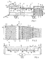
- the integrated and movable apparatus comprises a frame 2, which is movable by means of wheels 3 and can be hooked with a coupling part 4 to a lorry, for example.
- a platform 5 On the right hand or supply side of the apparatus 1 there is a platform 5, on which a stack of bricks S is put.
- the platform 5 can be moved up and down along a guide 6. This takes place with the help of a motor, not shown, which can be operated with the help of an operable and adjustable control apparatus 21.
- An outrigger 7 attached to the frame 2 extends, as seen in the drawing, to the right and above the stack S.
- a slide 8 is arranged, which is movable back and forth in a driven manner along the outrigger 7 in the directions of the arrow B.
- the vibrating plate 10' can be extended on the upstream side for defining a supply table while the pack of bricks S is placed ahead of that on a jack-up platform.
- a separate gripping tool comprising a front clamping strip of a rear clamping strip, the upper layer of bricks is then, whilst being clamped, slid onto the supply table, until all the bricks are supported by it.
- a fixed lateral guide and a lateral guide which is transversely adjustable ensure that the supplied layer of bricks is placed exactly in front of the entrances to the guide paths which are to be discussed below. Then the front clamping strip, which also ensured that the preceding group of bricks moved up, is lifted up and the layer of bricks is then pushed along to some extent with the rear clamping strip.
- the vibrating plate 10' also terminates at the downstream end of the guide plates 9 and a few centimetres (for example 2 cm) above that there is the upstream end of the following vibration plate 10'', which forms the support surface at the converting and laying parts of the apparatus 1.
- the upstream end of vibrating plate 10'' and the downstream end of vibrating plate 10' preferably engage in a finger or tooth fashion into one another as seen in vertical projection, whilst leaving intermediate small vertical passages clear for pusher rods 12 which are arranged just beneath the vibrating plate 10' (see figure 1A) and which are movable up and down (directions D).
- the upstream end of the vibrating plate 10'' forms a shoulder 11, against which the bricks delivered by brick supplied through brick paths come to rest, to then, on command, be tipped up by the upward movement of selected pusher rods, so as to arrive with the lower front edge on the vibrating plate 10'' and to be subsequently transported further on it under the influence of the vibrations.
- a converting device Downstream from the shoulder 11 a converting device is arranged, which is attached by means of posts 15 to the frame 1. This converting device will be discussed below in detail.
- the base Downstream from the converting apparatus 14 is the place where the herringbone brick module is finally formed.
- the base there is formed by the vibrating plate 10, while an end jig 23 is arranged transversely on the left hand end side.
- This end jig 23 is movable in the direction F and is then guided by two lateral guides 22, which moreover serve for laterally confining the bricks included in the module.
- the end jig 23 and the lateral guides 22 are selected and/or adjusted to the practical brick size and the dimensions of the desired module.
- a taking-up apparatus 24 is arranged on the discharge end of the apparatus 1.
- the latter is attached by means of posts 28 tot the frame 2 and provided with an articulated working arm 27, at the end of which a frame 25 is attached, to which a series of suction cups 26 is attached.
- the frame 25 and thus the suction cups 26 are movable up and down in the directions G, to be brought into engagement with the bricks.
- the working arm 27 is swivellable in the horizontal to displace the frame 25 with suction cups 26 and bricks sucked firmly by it to the left in the direction H in order to deliver the bricks into the paving work (not shown).
- first of all stack S of bricks is delivered to the platform 5 by a fork-lift truck.
- the platform 5 is then adjusted along guide 6 to such a height that the bottom side of the upper layer of bricks is at level with the surface of the vibrating plane 10'.
- the vibrating plane 10' is made to vibrate and the slide 8 is moved to the left, in the course of which the slide 8 moves the upper layer of bricks to the left onto the vibrating plane 10'.
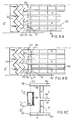
- the pusher rods for the uneven rows will then be coupled with each other and the pusher rods for the even rows will be coupled with each other.
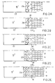
- the pusher rods 12 for the even rows b, d etc. have been lifted for a while.
- a brick has been let through.
- These bricks are received by the end jig 23 provided with a zigzag shaped end plane.
- This end jig 23 is adjustable or is selected for the size of the brick to be handled.
- the end jig 23 is held at a place such that for a moment the bricks b, d, etc. are restrained with their vertical left front rib.
- the end jig is displaced along a distance of 1 ⁇ 2 ⁇ 2 the (practical) width, across the vibrating plane and guided by the guides 22.
- the bricks a, c, e etc. then come in a position which is comparable to that of the bricks b, d, etc., in figure 2B, but now rest with their right hand front rib against a head face of those bricks b, d, etc. instead of against the contact plane of the end jig 23.
- the converting apparatus 14 is operated once more, but now in such a way that the cylinder 16 is moved vis-à-vis the piston rods 17 in the direction E2.
- the pusher bars 18 are then pressed against the left side faces of the bricks a, c, e etc. as a result of which said bricks, as seen on paper, are turned to the left, during which movement the right hand front rib which makes contact will slide along the head face of the bricks b, d etc. and then along the contact plane of the end jig 23.
- the head faces of the bricks a, c, e, etc. have arrived at the contact plane of the end jig 23, the first herringbone patterned row is completely ready.
- the lock 11 is then operated to allow the next row of bricks b, d etc. through, while the end jig is again moved over a distance of 1 ⁇ 2 ⁇ 2 the (practical) width of the brick.
- the bricks b, d, etc. do not abut with their left hand front rib against the contact plane of the end jig 23, but instead the head face of the bricks a, c, e, etc. which have just been arranged.
- the contact plane of the end jig 23 is now replaced by a contact plane which is formed by the free faces of the bricks which face the upstream direction of the first row just arranged.
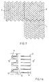
- the brick module T of 12 x 9 bricks laid in herringbone pattern is ready.
- a brick module T or placing layer with a precisely determined circumference is obtained.
- the module can be held to be concentrated in the centre of gravity surface Z without any loss of accuracy.
- the frame 25 with suction cups 26 can be aligned to this centre of gravity Z.
- the point of orientation Z which is decisive for the module T is then, as it were, transferred to the take-up and laying means 24.
- a suchlike point of orientation can be coupled in a way known to the expert with aligning means which have been installed for that purpose in the paving work and which measure the average position of modules previously placed in the work. Controlled by signals to be delivered by the aligning means, the laying means 24 will then be able to place the frame 25 and the suction cups 26 in exactly the correct position, after which the suction cups 26 are deactivated and the bricks can be left behind in the sand bed in the paving work.
- the suction cups 26 are preferably composed as the suction cups in the Dutch patent application no. 86.00820.
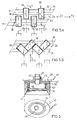
- a suchlike suction cup made as a composite spring is shown with the reference number 26 in figure 6 and has a disc-shaped covering plate 42 with a hollow cylinder 43 of rubber of the like, in particular foam rubber with a closed cell structure, or massive soft rubber which is glued or vulcanized onto it.
- the rubber cylinder 43 tapers conically at the bottom in a thin suction edge 44, which when pressing down the suction cup 41 onto a brick deforms over a considerable length so that to perform a certain suction force quite a low suction pressure is required.
- a central suction opening 45 is provided in the covering plate 42, into which a suction pipe 46 can be screwed, which can be secured by means of a screw head, or as represented, with a nut 47 to an attachment plate 48 of a suction unit.
- a suction connection is to be attached to the suction pipe 46, with therein a non-return valve.
- a ring strip 50 is accomodated loosably with an interference fit in the cylinder cavity 49, which strip counteracts lateral deflection of the rubber cylinder 43 under the suction pressure exerted thereon.
- a helix 51 is accomodated in the rubber casing 43, as a result of which the rubber casing shows a compression course which at first has a slack and later has a stiff compression characteristic, so as to be usable on heavy bricks.
- the rubber casing 43 according to the invention oval (with two axes of symmetry perpendicular to each other) or ellipse shaped in cross section, the bricks can be taken up with a very efficient use of suction force and can be transferred securely. It is noted that, whilst maintaining the oval or ellipse shape, suction cups in which there is no helix can also be used.
- the apparatus 24 can be swung back to above the place where already the next module is being made.
- the platform 5 and the slide 8 are operated in such a way that the stack S is lifted step by step and each time a layer of bricks is slid onto the vibrating plane. In this way a machine 1 is obtained, which can function fully automatically.
- aligning means are used in the paving work, only the regular moving of the frame 2 has to be seen to, depending on the range of the working arm 27, and of regular supply of new stacks S.
- These stacks S can either consist of used bricks or new bricks.
- the converting apparatus 14' comprises a lazy-tongs structure (Neurenberger tongs) which is built up of three rods 29, 30 and 31 arranged transversely above the vibrating plate 10'', the rod 29 being slidably arranged in the direction C and in horizontal direction and the rod 30 being fixedly arranged downstream, laterally therefrom and the rod 31 arranged upstream thereform in the direction C.
- the rods 30 en 31 are hinged to the middel rod 29 in a parallelogram manner.
- the connections between the rods 29 and 31 and the rods 29 and 30 are formed by series of brick catchers 38, each of which is formed by an upper plate 37 and a U-shaped wall set 36 welding against that.
- This wall set 36 is arranged in such a way, that the open side of the U-shape is directed to the supplying side of the bricks.
- the one series of the plates 37 is attached by hinge connections 32 to the downstream rod 30 and with hinge connections 33 to the middle rod 29, while the other series of plates 36 is attached to the middle rod 29 by hinge connections 34 and by hinge connections 35 to the upstream rod 31.
- figure 5A is a bottom view, i.e. on its lower edge the U-shaped wall 37 projects freely. This means that when a brick is accomodated therein this brick can maintain contact with the vibrating plate 10'' above which the converting apparatus is arranged.
- the rod 29 is connected to moving means, not shown, which are driven by the operation and controlling means 21 and are arranged to move the rod 29, as seen in the drawing, to the right in the direction E2 (or, alternatively, to the left in the direction E1) (and back again), in the course of which this rod will then move according to a parallelogram movement to the right and upwards against the rod 30 and the rod 31 via-à-vis the rod 30 upwards and vis-à-vis the rod 29 upwards and to the left, until the situation as shown in figure 5B is reached.
- the transverse distance between the points 32 and 35 is the same again as that of the brick supply paths, that is 1 ⁇ 2 ⁇ 2L.
- the bricks (e and c) and (b and d) respectively have been turned about the points 32 and 35, without being disturbed by the adjacent bricks.
- a complete transverse series of bricks of the uneven rows a, c etc. and the even rows b, d, etc. are delivered in one go, and these bricks have been received in the U-shaped brick catchers 38 intended for that purpose, they will be urged into a herringbone pattern by the movement of the rods 29 and 31.
- the U-shaped brick catchers 38 have dimensions vis-à-vis the bricks to be handled, such that the latter are turned in a sufficiently secure way.
- lifting means see to it that the lazy-tongs structure is lifted sufficiently far, to permit free further movement in the direction C of the bricks in herringbone pattern to the module to be made. It is ensured that the contact planes of the end jig 23 or those of the rows which are laid in herringbone pattern afterwards, are sufficiently nearby.
- each type of brick has its own optimum arrangement as far as the converting means are concerned.
- Variables can, among others, be the roller speed, the roughness of the roller surface, the length of the elongation of the longitudinal guide.
- An alternative for the converting means according to the principle of the figures 8A-C is the arrangement according to the figures 9A, B and C, the axis 62 being substituted by a pipe 162, the centre line of which is placed at approximately 1 ⁇ 2 L (half the brick length) downstream the shoulder 111.
- the pipe 162 is attached rotatably about its axis to the frame which corresponds to the frame 1 of figure 1, and is connetected with drive means not shown for its rotation in direction of revolution S.
- the pipe 162 is provided with thickened portions 163, which are, for example, formed by two semi-cylindrical shaped shells 170, 171 which project at most over a 1 ⁇ 2 B in the path of a brick and are attached on the pipe 162 and are provided on their outer side with a layer of synthetic material 172, 173 vulcanized thereon.
- the synthetic coverings 172, 173 are preferably formed of a rough synthetic material in order to generate as many frictional forces as possible.
- the brick will lie clear next to the thickened portions 163. Tilting of the brick in the vertical plane is prevented by the guide 160, against which the brick can find support with its side face.
- the pipe can be provided with a covering 174 of a synthetic material which projects at least approximately just as far radially.
- the synthetic coverings 172, 173 on the one hand and 174 on the other hand can be chosen such that the former coverings are rougher than the latter, so as to accelerate the brick half which rests thereon vis-à-vis the brick half which is above the relatively smooth synthetic surface by transmission of a larger, accelerating frictional force alone.
- FIG 9B a vertical view of the transition at the location of the converting means 162 is shown schematically.
- the shoulder 111 is formed by a plate 180, which is attached by a rubber body 182 to an angle iron 183.
- a foam rubber filling piece 181 is placed between the plate 180 and angle iron 183.
- the upper side of the plate 180, the foam rubber filling piece 181 and angle iron 183 is at least approximately in the same plane as the horizontal tangent plane on the roller 162 and the upper surface of supporting plane 110'' which is arranged to vibrate.
- Angle iron 183 is attached securely to the frame of the machine.
Landscapes
- Engineering & Computer Science (AREA)
- Architecture (AREA)
- Civil Engineering (AREA)
- Structural Engineering (AREA)
- Devices For Post-Treatments, Processing, Supply, Discharge, And Other Processes (AREA)
- Road Paving Machines (AREA)
Claims (18)
- Procédé de transformation d'une couche initiale de briques de pavage, qui sont disposées suivant un agencement à orientation uniforme, en une couche de mise en place de briques de pavage, qui sont disposées suivant un agencement mutuel à chevrons, dans lequel les briques de la couche initiale sont présentées d'une façon parallèle à un moyen de rotation de brique, afin d'être forcées ainsi dans le plan horizontal vers une orientation formant un angle avec la direction de progression, caractérisé en ce que les briques sont fournies rangée par rangée, dans la direction de progression audit moyen de rotation de brique, et sont ensuite avancées jusqu'en butée contre un moyen de butée en forme de chevrons pouvant être manoeuvré dans la direction de progression inverse, dans lequel les briques latéralement externes sont guidées et maintenues par des moyens de gabarit de guidage, dans lequel le moyen de butée en forme de chevrons comprend un gabarit actionne d'extrémité en forme de chevrons, qui est déplacé au fur et to a mesure de la formation des rangées de chevrons suivant la direction de progression.
- Procédé selon la revendication 1, dans lequel les moyens de gabarit de guidage peuvent être réglés à une distance mutuelle de (n1.L+B)-½
- Procédé selon la revendication 1 ou 2, dans lequel la couche de mise en place est prélevée par un moyen de prélèvement qui est positionné par rapport au centre de gravité de la couche de mise en place, les briques étant, de préférence, chacune prélevée au moyen d'une ou plusieurs ventouses.
- Procédé selon la revendication 3, dans lequel la couche de placement est transférée vers un chantier de pavage à l'aide du moyen de prélèvement, et y est orientée de la façon correcte à l'aide d'un moyen de positionnement qui détecte le centre de gravité de la couche de mise en place, et est ensuite abaissée jusque sur le chantier de pavage, dans lequel le moyen de positionnement comprend de préférence un gabarit qui doit être placé sur le chantier.
- Dispositif destiné à transformer une couche initiale de briques de pavage, qui sont disposées suivant un agencement mutuel à orientation uniforme, en une couche de mise en place (T) de briques de pavage, qui sont disposées suivant un agencement mutuel en chevrons, comprenant un châssis (2), un moyen de support (5) sur le châssis destiné à supporter un paquet (S) de couches initiales empilées, un moyen d'enlèvement (7, 8) destiné à enlever une couche initiale du paquet, un moyen de réorientation (14 ; 14', 29, 30, 31 ; 60, 63) destiné à réorienter les briques provenant de la couche initiale vers une orientation mutuelle en chevrons, et un moyen de prélèvement (24) destiné à prélever et à transférer la couche de mise en place vers un chantier de pavage, caractérisé par un premier moyen de transport (10') destiné à transporter les briques depuis le moyen d'enlèvement jusqu'au moyen de réorientation, un moyen de réception (22, 23) destiné à recevoir les briques réorientées suivant une disposition en chevrons et à les maintenir dans une couche de mise en place suivant un agencement en chevrons, et un second moyen de transport (10") destiné à transporter les pavés depuis le moyen de réorientation (14, 14', 29, 30, 31 ; 60, 63) vers le moyen de réception, dans lequel le moyen de réception comprend un plan de support (10") et un gabarit d'extrémité (23) comportant une paroi de contact qui correspond à l'agencement en chevrons, le dispositif comprenant en outre un moyen destiné à déplacer le gabarit d'extrémité (23) dans la direction de progression du second moyen de transport.
- Dispositif selon la revendication 5, dans lequel le moyen de réception (22, 23) comprend un moyen de maintien (22) destiné à maintenir les briques disposées en agencement en chevrons suivant une direction transversale à la direction de progression.
- Dispositif selon la revendication 5 ou 6, comprenant un moyen de guidage de briques (9 ; 109) placé en amont du moyen de réorientation (14, 14', 29, 30, 31 ; 60, 63) destiné à espacer les briques suivant la direction transversale d'une distance d'axe en axe de ½
- Dispositif selon la revendication 7, dans lequel le moyen de réorientation (14 ; 14', 29, 30, 31 ; 60, 63) est agencé de façon à venir en contact avec les briques en vue de la rotation de celles-ci vers une orientation en chevrons tout en conservant au moins pratiquement la distance mutuelle d'axe en axe suivant la direction transversale des briques.
- Dispositif selon l'une quelconque des revendications 5 à 8, dans lequel le moyen de réorientation (60, 63 ; 160, 163) comprend un moyen d'entraínement (63 ; 163) destiné à venir en contact avec les briques en les entraínant suivant la direction du transport à un emplacement situé sur une première moitié longitudinale de ces briques de manière à accélérer cette première moitié longitudinale suivant la direction du transport par rapport à la seconde moitié longitudinale adjacente, et un moyen d'appui (65 ; 165) destiné à créer un point de rotation pour la seconde moitié longitudinale de ces briques par venue en contact avec un endroit sur ladite seconde moitié.
- Dispositif selon la revendication 9, dans lequel le moyen d'entraínement comprend des rouleaux menés (63 ; 163), qui sont agencés de façon à venir en contact avec la face inférieure des briques.
- Dispositif selon la revendication 10, dans lequel les rouleaux d'entraínement (63 ; 163) sont placés de façon à faire saillie dans un évidement du plan de support (10" ; 110") de manière à venir en contact avec la première moitié longitudinale des briques, tandis que la seconde moitié longitudinale supportée dans le plan de support (10" ; 110"), les rouleaux d'entraínement étant, de préférence, placés dans chaque cas dans deux voies d'alimentation de briques adjacentes.
- Dispositif selon la revendication 10, dans lequel les rouleaux d'entraínement comportent une première partie qui est munie d'une surface rugueuse ainsi qu'une seconde partie qui est munie d'une surface lisse, dans lequel la première partie et la seconde partie sont placées, suivant la direction axiale, l'une après l'autre de façon à venir en contact avec la première et avec la seconde moitié longitudinale de la brique, respectivement.
- Dispositif selon la revendication 10, dans lequel les rouleaux (163), observés suivant la direction de leur axe, présentent des dimensions telles que les secondes moitiés longitudinales des briques sont au moins exemptes de support sur une partie de la surface inférieure de celles-ci, et les moyens d'appui (160 ; 165) sont agencés de façon à empêcher le basculement des briques dans un plan vertical et, de préférence, exercent des forces de frottement de décélération sur la seconde moitié longitudinale des briques.
- Dispositif selon les revendications 9 à 13, dans lequel les moyens d'appui (60 ; 160) sont formés par des glissières longitudinales allongées (9a ; 109a) s'étendant suivant la direction du transport jusqu'au-delà des rouleaux d'entraínement (63 ; 163), qui sont espacées suivant la direction transversale à des distances d'approximativement deux rangées de briques, et alternent suivant la direction transversale avec des glissières longitudinales plus courtes, qui sont espacées suivant la direction transversale à des distances d'approximativement deux rangées de briques, dans lequel les rouleaux d'entraínement, observés suivant la direction du transport, sont agencés en aval des extrémités des glissières longitudinales courtes (9b ; 109b) et pratiquement en amont de l'extrémité des glissières longitudinales allongées, dans lequel le premier moyen de transport comprend un moyen (11, 12 ; 111, 112) destiné à présenter en alternance, au moyen de réorientation, des séries transversales de briques qui, observées suivant la direction transversale, sont situées à des emplacements 2n et 2n - 1, respectivement.
- Dispositif selon l'une quelconque des revendications 5 à 8, dans lequel le moyen de réorientation (14, 18) comprend des moyens de rotation (18), qui sont placés de façon to a venir en contact avec le côté des briques à une certaine distance du milieu horizontal de celles-ci, de même qu'un moyen d'entraínement destiné au moyen de réorientation afin de faire tourner les briques dans le plan horizontal après la venue en contact de celles-ci.
- Dispositif selon la revendication 15, dans lequel les moyens de rotation comprennent des barres de poussée (18), qui dépendent d'un dispositif de suspension, alignées avec les espacements entre les briques espacées suivant la direction transversale, et dans lequel le premier moyen de transport (10') comprend un moyen (11, 12) destiné à présenter en alternance, au moyen de réorientation (14), des séries transversales de briques qui, observées suivant la direction transversale, sont situées à des emplacements 2n et 2n-1, respectivement, dans lequel le moyen d'entraínement est conçu pour solliciter les barres de poussée en alternance suivant une première direction transversale et suivant la direction opposée.
- Dispositif selon l'une quelconque des revendications 5 à 8, dans lequel le moyen de réorientation (14') comprend une pince extensible double, comportant trois tiges (29, 30, 31), qui sont reliées l'une à l'autre à la manière d'un parallélogramme, et sont agencées horizontalement et transversalement à la direction de progression du moyen de transport, dans lequel la première tige amont (31) et la seconde tige médiane (30) sont articulées l'une par rapport à l'autre par une série de premières cavités pour briques (38), et la troisième tige aval (29) et la seconde tige médiane (30) sont articulées l'une par rapport à l'autre par une série de secondes cavités pour briques (38), dans lequel les première et seconde cavités pour briques (38) comportent de préférence des ouvertures de réception de briques en forme de U, qui sont orientées de façon à recevoir et loger les briques dans une première position d'articulation de la pince, et sont orientées en biais dans une seconde position d'articulation de la pince, et dans lequel le dispositif comprend un moyen destiné à soulever et abaisser la pince, dans lequel, de préférence, la troisième tige (29) est disposée de façon fixe, la seconde tige (30) est disposée de façon à pouvoir coulisser en mouvement alternatif suivant une direction transversale et suivant une direction de progression, et la première tige (31) est disposée de façon à pouvoir coulisser en mouvement alternatif, un moyen d'entraínement étant présent afin de faire coulisser la seconde tige suivant la direction transversale afin de faire tourner les première et seconde cavités pour briques, respectivement, autour de leurs fixations d'articulation (35, 34) sur les première et seconde tiges.
- Dispositif selon l'une quelconque des revendications 5 à 17, dans lequel le moyen de prélèvement (24) agit avec une force d'aspiration et comprend des ventouses (26, 41), qui peuvent être chacune amenée jusqu'en contact d'aspiration avec une brique, dans lequel les ventouses sont munies d'une enveloppe de caoutchouc (43), qui est de section ovale ou circulaire.
Applications Claiming Priority (2)
| Application Number | Priority Date | Filing Date | Title |
|---|---|---|---|
| NL9301484A NL9301484A (nl) | 1993-08-27 | 1993-08-27 | Werkwijze en inrichting voor het omvormen van lagen straatstenen van een gelijkgericht, uitgangsverband naar een gekeperd legverband. |
| NL9301484 | 1993-08-27 |
Publications (2)
| Publication Number | Publication Date |
|---|---|
| EP0640721A1 EP0640721A1 (fr) | 1995-03-01 |
| EP0640721B1 true EP0640721B1 (fr) | 1999-10-20 |
Family
ID=19862804
Family Applications (1)
| Application Number | Title | Priority Date | Filing Date |
|---|---|---|---|
| EP19940202463 Expired - Lifetime EP0640721B1 (fr) | 1993-08-27 | 1994-08-29 | Procédé et dispositif pour transformer des couches de pierres à paver orientées uniformément dans un stade initial dans un dessin à chevrons |
Country Status (3)
| Country | Link |
|---|---|
| EP (1) | EP0640721B1 (fr) |
| DE (1) | DE69421231D1 (fr) |
| NL (1) | NL9301484A (fr) |
Families Citing this family (11)
| Publication number | Priority date | Publication date | Assignee | Title |
|---|---|---|---|---|
| DK175952B1 (da) | 2003-04-28 | 2005-08-22 | Kvm Industrimaskiner As | Fremgangsmåde til sortering af belægningssten |
| NL1026269C2 (nl) | 2004-05-26 | 2005-11-30 | Arend Luijten | Werkwijze en inrichting voor het maken van een keperverband van stenen. |
| NL2001093C2 (nl) | 2007-12-14 | 2009-06-16 | Crh Kleiwaren Beheer B V | Bestratingsmachine. |
| DE102010030890A1 (de) * | 2010-07-02 | 2012-01-05 | Baustoffwerke Gebhart & Söhne GmbH & Co.KG | Verfahren und Vorrichtung zum Gruppieren von Steinen, insbesondere Betonpflastersteinen |
| CN107881890B (zh) * | 2017-11-24 | 2023-03-24 | 山东港湾建设集团有限公司 | 联锁块大面积铺砌的辅助系统及其实现方法 |
| CN108532424A (zh) * | 2018-06-21 | 2018-09-14 | 李志刚 | 一种市政道路青红砖无需变向间隔铺设设备 |
| CN112281601B (zh) * | 2020-10-22 | 2021-11-23 | 海宁金都新能源有限公司 | 一种路面铺砖装置 |
| CN113718602A (zh) * | 2020-12-24 | 2021-11-30 | 安徽丰林建设工程有限公司 | 一种市政工程用铺砖设备 |
| CN114150556A (zh) * | 2021-11-10 | 2022-03-08 | 天津市远成景观建设发展有限公司 | 一种冬季卵石铺装结构及其施工工艺 |
| CN115354544B (zh) * | 2022-01-05 | 2023-04-28 | 湖北理工学院 | 一种道路地砖铺设装置 |
| NL1044537B1 (nl) * | 2023-01-31 | 2024-08-22 | Petrus Maria Van Kuijk Hendricus | Bestratingsmachine |
Family Cites Families (3)
| Publication number | Priority date | Publication date | Assignee | Title |
|---|---|---|---|---|
| NL8201109A (nl) * | 1982-03-17 | 1983-10-17 | Verheijen Maschf Bv | Werkwijze en inrichting voor het mechanisch leggen van een bestrating. |
| NL193667C (nl) * | 1986-04-01 | 2000-06-06 | Luijten Arend | Werkwijze voor het mechanisch leggen van stenen in keperverband. |
| NL8602633A (nl) * | 1986-10-21 | 1988-05-16 | Luyten Holding B V | Werkwijze voor het mechanisch leggen van stenen in keperverband, en een inrichting daarvoor. |
-
1993
- 1993-08-27 NL NL9301484A patent/NL9301484A/nl not_active Application Discontinuation
-
1994
- 1994-08-29 EP EP19940202463 patent/EP0640721B1/fr not_active Expired - Lifetime
- 1994-08-29 DE DE69421231T patent/DE69421231D1/de not_active Expired - Lifetime
Also Published As
| Publication number | Publication date |
|---|---|
| DE69421231D1 (de) | 1999-11-25 |
| EP0640721A1 (fr) | 1995-03-01 |
| NL9301484A (nl) | 1995-03-16 |
Similar Documents
| Publication | Publication Date | Title |
|---|---|---|
| US5379513A (en) | Automated nailing device | |
| CN110984537B (zh) | 一种墙面贴砖机的贴砖方法 | |
| EP0640721A1 (fr) | Procédé et dispositif pour transformer des couches de pierres à paver orientées uniformément dans un stade initial dans un dessin à chevrons | |
| US5051058A (en) | Apparatus for palletizing stacks of paper sheets and the like | |
| CN106042446B (zh) | 加工不同型号纸板的模切机自动供料和上料装置及方法 | |
| CN112299023B (zh) | 砖块码垛系统 | |
| CN108974459B (zh) | 一种袋装纸尿裤翻转整理系统 | |
| CN114043615B (zh) | 全自动垫块生产线 | |
| FR2614285A1 (fr) | Perfectionnements apportes aux dispositifs d'empilage d'objets, tels que des boites, sur des palettes. | |
| EP2071081A1 (fr) | Machine de pavage | |
| CA1065641A (fr) | Machine et methode pour fabriquer des panneaux en blocs de beton | |
| CN106827274A (zh) | 硅棒截断设备及硅棒截断方法 | |
| CN209583440U (zh) | 一种全自动龙门式高位板砖分离码垛机 | |
| CN113998199A (zh) | 一种自动码垛机 | |
| CN111451653B (zh) | 一种激光切管机机器人码垛系统用垛盘机构 | |
| US5290165A (en) | Independent pallet delivery system | |
| KR100454451B1 (ko) | 상승 및 하강 이동 발생장치 | |
| CN112281601B (zh) | 一种路面铺砖装置 | |
| CN118025877B (zh) | 一种瓦楞纸生产专用机械手 | |
| CN117262734B (zh) | 一种石材修补加工流水线 | |
| CN119059056A (zh) | 一种大米包装码垛装置 | |
| CN218142424U (zh) | 一种包角机 | |
| CN115520645B (zh) | 一种石材自动卸板机 | |
| CN105923404A (zh) | 一种砖窑自动码坯机 | |
| CN216333089U (zh) | 一种自动码垛机 |
Legal Events
| Date | Code | Title | Description |
|---|---|---|---|
| PUAI | Public reference made under article 153(3) epc to a published international application that has entered the european phase |
Free format text: ORIGINAL CODE: 0009012 |
|
| AK | Designated contracting states |
Kind code of ref document: A1 Designated state(s): BE DE FR GB NL |
|
| RAX | Requested extension states of the european patent have changed |
Free format text: SI |
|
| 17P | Request for examination filed |
Effective date: 19950830 |
|
| 17Q | First examination report despatched |
Effective date: 19970414 |
|
| GRAG | Despatch of communication of intention to grant |
Free format text: ORIGINAL CODE: EPIDOS AGRA |
|
| GRAG | Despatch of communication of intention to grant |
Free format text: ORIGINAL CODE: EPIDOS AGRA |
|
| GRAG | Despatch of communication of intention to grant |
Free format text: ORIGINAL CODE: EPIDOS AGRA |
|
| GRAH | Despatch of communication of intention to grant a patent |
Free format text: ORIGINAL CODE: EPIDOS IGRA |
|
| GRAH | Despatch of communication of intention to grant a patent |
Free format text: ORIGINAL CODE: EPIDOS IGRA |
|
| GRAH | Despatch of communication of intention to grant a patent |
Free format text: ORIGINAL CODE: EPIDOS IGRA |
|
| GRAA | (expected) grant |
Free format text: ORIGINAL CODE: 0009210 |
|
| AK | Designated contracting states |
Kind code of ref document: B1 Designated state(s): BE DE FR GB NL |
|
| DAX | Request for extension of the european patent (deleted) | ||
| PG25 | Lapsed in a contracting state [announced via postgrant information from national office to epo] |
Ref country code: FR Free format text: LAPSE BECAUSE OF FAILURE TO SUBMIT A TRANSLATION OF THE DESCRIPTION OR TO PAY THE FEE WITHIN THE PRESCRIBED TIME-LIMIT Effective date: 19991020 |
|
| RTI1 | Title (correction) |
Free format text: METHOD AND APPARATUS FOR TRANSFORMING LAYERS OF PAVING BRICKS FROM A UNIFORMLY ORIENTED INITIAL PATTERN TO A HERRINGBONE LAYING PATTERN |
|
| REF | Corresponds to: |
Ref document number: 69421231 Country of ref document: DE Date of ref document: 19991125 |
|
| PG25 | Lapsed in a contracting state [announced via postgrant information from national office to epo] |
Ref country code: DE Free format text: LAPSE BECAUSE OF FAILURE TO SUBMIT A TRANSLATION OF THE DESCRIPTION OR TO PAY THE FEE WITHIN THE PRESCRIBED TIME-LIMIT Effective date: 20000121 |
|
| EN | Fr: translation not filed | ||
| PLBE | No opposition filed within time limit |
Free format text: ORIGINAL CODE: 0009261 |
|
| STAA | Information on the status of an ep patent application or granted ep patent |
Free format text: STATUS: NO OPPOSITION FILED WITHIN TIME LIMIT |
|
| 26N | No opposition filed | ||
| REG | Reference to a national code |
Ref country code: GB Ref legal event code: IF02 |
|
| PGFP | Annual fee paid to national office [announced via postgrant information from national office to epo] |
Ref country code: GB Payment date: 20030827 Year of fee payment: 10 |
|
| PGFP | Annual fee paid to national office [announced via postgrant information from national office to epo] |
Ref country code: BE Payment date: 20030910 Year of fee payment: 10 |
|
| PG25 | Lapsed in a contracting state [announced via postgrant information from national office to epo] |
Ref country code: GB Free format text: LAPSE BECAUSE OF NON-PAYMENT OF DUE FEES Effective date: 20040829 |
|
| PG25 | Lapsed in a contracting state [announced via postgrant information from national office to epo] |
Ref country code: BE Free format text: LAPSE BECAUSE OF NON-PAYMENT OF DUE FEES Effective date: 20040831 |
|
| BERE | Be: lapsed |
Owner name: *LUIJTEN AREND Effective date: 20040831 |
|
| GBPC | Gb: european patent ceased through non-payment of renewal fee |
Effective date: 20040829 |
|
| PGFP | Annual fee paid to national office [announced via postgrant information from national office to epo] |
Ref country code: NL Payment date: 20050831 Year of fee payment: 12 |
|
| PG25 | Lapsed in a contracting state [announced via postgrant information from national office to epo] |
Ref country code: NL Free format text: LAPSE BECAUSE OF NON-PAYMENT OF DUE FEES Effective date: 20070301 |
|
| NLV4 | Nl: lapsed or anulled due to non-payment of the annual fee |
Effective date: 20070301 |
|
| BERE | Be: lapsed |
Owner name: *LUIJTEN AREND Effective date: 20040831 |