EP0640776A2 - Mécanisme d'équilibrage pour moteur à combustion interne - Google Patents
Mécanisme d'équilibrage pour moteur à combustion interne Download PDFInfo
- Publication number
- EP0640776A2 EP0640776A2 EP94113532A EP94113532A EP0640776A2 EP 0640776 A2 EP0640776 A2 EP 0640776A2 EP 94113532 A EP94113532 A EP 94113532A EP 94113532 A EP94113532 A EP 94113532A EP 0640776 A2 EP0640776 A2 EP 0640776A2
- Authority
- EP
- European Patent Office
- Prior art keywords
- balancing shaft
- balancing
- crankshaft
- combustion engine
- internal
- Prior art date
- Legal status (The legal status is an assumption and is not a legal conclusion. Google has not performed a legal analysis and makes no representation as to the accuracy of the status listed.)
- Granted
Links
Images




Classifications
-
- F—MECHANICAL ENGINEERING; LIGHTING; HEATING; WEAPONS; BLASTING
- F02—COMBUSTION ENGINES; HOT-GAS OR COMBUSTION-PRODUCT ENGINE PLANTS
- F02B—INTERNAL-COMBUSTION PISTON ENGINES; COMBUSTION ENGINES IN GENERAL
- F02B75/00—Other engines
- F02B75/16—Engines characterised by number of cylinders, e.g. single-cylinder engines
- F02B75/18—Multi-cylinder engines
- F02B75/20—Multi-cylinder engines with cylinders all in one line
-
- F—MECHANICAL ENGINEERING; LIGHTING; HEATING; WEAPONS; BLASTING
- F02—COMBUSTION ENGINES; HOT-GAS OR COMBUSTION-PRODUCT ENGINE PLANTS
- F02B—INTERNAL-COMBUSTION PISTON ENGINES; COMBUSTION ENGINES IN GENERAL
- F02B61/00—Adaptations of engines for driving vehicles or for driving propellers; Combinations of engines with gearing
- F02B61/02—Adaptations of engines for driving vehicles or for driving propellers; Combinations of engines with gearing for driving cycles
-
- F—MECHANICAL ENGINEERING; LIGHTING; HEATING; WEAPONS; BLASTING
- F16—ENGINEERING ELEMENTS AND UNITS; GENERAL MEASURES FOR PRODUCING AND MAINTAINING EFFECTIVE FUNCTIONING OF MACHINES OR INSTALLATIONS; THERMAL INSULATION IN GENERAL
- F16F—SPRINGS; SHOCK-ABSORBERS; MEANS FOR DAMPING VIBRATION
- F16F15/00—Suppression of vibrations in systems; Means or arrangements for avoiding or reducing out-of-balance forces, e.g. due to motion
- F16F15/22—Compensation of inertia forces
- F16F15/26—Compensation of inertia forces of crankshaft systems using solid masses, other than the ordinary pistons, moving with the system, i.e. masses connected through a kinematic mechanism or gear system
- F16F15/264—Rotating balancer shafts
-
- F—MECHANICAL ENGINEERING; LIGHTING; HEATING; WEAPONS; BLASTING
- F16—ENGINEERING ELEMENTS AND UNITS; GENERAL MEASURES FOR PRODUCING AND MAINTAINING EFFECTIVE FUNCTIONING OF MACHINES OR INSTALLATIONS; THERMAL INSULATION IN GENERAL
- F16F—SPRINGS; SHOCK-ABSORBERS; MEANS FOR DAMPING VIBRATION
- F16F15/00—Suppression of vibrations in systems; Means or arrangements for avoiding or reducing out-of-balance forces, e.g. due to motion
- F16F15/22—Compensation of inertia forces
- F16F15/26—Compensation of inertia forces of crankshaft systems using solid masses, other than the ordinary pistons, moving with the system, i.e. masses connected through a kinematic mechanism or gear system
- F16F15/264—Rotating balancer shafts
- F16F15/268—Hollow shafts
-
- F—MECHANICAL ENGINEERING; LIGHTING; HEATING; WEAPONS; BLASTING
- F02—COMBUSTION ENGINES; HOT-GAS OR COMBUSTION-PRODUCT ENGINE PLANTS
- F02B—INTERNAL-COMBUSTION PISTON ENGINES; COMBUSTION ENGINES IN GENERAL
- F02B75/00—Other engines
- F02B75/02—Engines characterised by their cycles, e.g. six-stroke
- F02B2075/022—Engines characterised by their cycles, e.g. six-stroke having less than six strokes per cycle
- F02B2075/027—Engines characterised by their cycles, e.g. six-stroke having less than six strokes per cycle four
-
- F—MECHANICAL ENGINEERING; LIGHTING; HEATING; WEAPONS; BLASTING
- F02—COMBUSTION ENGINES; HOT-GAS OR COMBUSTION-PRODUCT ENGINE PLANTS
- F02B—INTERNAL-COMBUSTION PISTON ENGINES; COMBUSTION ENGINES IN GENERAL
- F02B75/00—Other engines
- F02B75/16—Engines characterised by number of cylinders, e.g. single-cylinder engines
- F02B75/18—Multi-cylinder engines
- F02B2075/1804—Number of cylinders
- F02B2075/1808—Number of cylinders two
-
- F—MECHANICAL ENGINEERING; LIGHTING; HEATING; WEAPONS; BLASTING
- F02—COMBUSTION ENGINES; HOT-GAS OR COMBUSTION-PRODUCT ENGINE PLANTS
- F02B—INTERNAL-COMBUSTION PISTON ENGINES; COMBUSTION ENGINES IN GENERAL
- F02B2275/00—Other engines, components or details, not provided for in other groups of this subclass
- F02B2275/18—DOHC [Double overhead camshaft]
-
- F—MECHANICAL ENGINEERING; LIGHTING; HEATING; WEAPONS; BLASTING
- F02—COMBUSTION ENGINES; HOT-GAS OR COMBUSTION-PRODUCT ENGINE PLANTS
- F02F—CYLINDERS, PISTONS OR CASINGS, FOR COMBUSTION ENGINES; ARRANGEMENTS OF SEALINGS IN COMBUSTION ENGINES
- F02F1/00—Cylinders; Cylinder heads
- F02F1/24—Cylinder heads
- F02F2001/244—Arrangement of valve stems in cylinder heads
- F02F2001/245—Arrangement of valve stems in cylinder heads the valve stems being orientated at an angle with the cylinder axis
- F02F2001/246—Arrangement of valve stems in cylinder heads the valve stems being orientated at an angle with the cylinder axis and orientated radially from the combustion chamber surface
-
- F—MECHANICAL ENGINEERING; LIGHTING; HEATING; WEAPONS; BLASTING
- F02—COMBUSTION ENGINES; HOT-GAS OR COMBUSTION-PRODUCT ENGINE PLANTS
- F02F—CYLINDERS, PISTONS OR CASINGS, FOR COMBUSTION ENGINES; ARRANGEMENTS OF SEALINGS IN COMBUSTION ENGINES
- F02F7/00—Casings, e.g. crankcases
- F02F7/006—Camshaft or pushrod housings
Definitions
- the present device relates to a compact balancing mechanism for an internal-combustion engine, having a balancing shaft disposed as close as possible to the crankshaft of the internal-combustion engine.
- the present invention relates to an internal-combustion engine provided with a balancing shaft which is rotated synchronously with the crankshaft in a direction reverse to the direction in which the crankshaft rotates at the same angular velocity as that at which the crankshaft rotates to balance the primary component of the inertial force of a reciprocating mass.
- Japanese Patent Laid-open (Kokai) No. 57-161333, a crankshaft 03 and a balancing shaft 05 are supported for rotation in parallel to each other on a crankcase 01.
- a thrust flange 06 is formed on the balancing shaft 05 so as to be in sliding contact with the side surface of a bearing portion 02 of the crankcase 01 to restrain the balancing shaft 05 from axial movement.
- the balancing shaft 05 is provided integrally with balance weights 07.
- Each balance weight 07 is positioned between the two adjacent crank webs 04 of the crankshaft 03.
- the diameter of the middle portion 09 of the balancing shaft 05 is equal to that of the journals 08 of the balancing shaft 05. Therefore, if the crankshaft 03 is disposed very close to the balancing shaft 05, the crank webs 04 of the crankshaft 03 collides against the middle portion 09 and the thrust flange 06 of the balancing shaft 05 and hence it is impossible to form the internal-combustion engine in a compact construction by disposing the balancing shaft 05 very close to the crankshaft 03.
- the balancing shaft and the crankshaft are interlocked by gears of the same dimensions mounted on the balancing shaft and the crankshaft so as to be meshed to drive the balancing shaft for rotation synchronous with the rotation of the crankshaft in a direction reverse to the direction of rotation of the crankshaft at the same angular velocity as that at which the crankshaft rotates.
- the balancing shaft and the crankshaft are provided with balance weights, respectively, so that the fixed angular relation between the balance weights is maintained to suppress the vibrations of the internal-combustion engine by balancing the inertial force of the reciprocating mass. Therefore, the two gears are fixedly mounted on the balancing shaft and the crankshaft and positioned relative to the balancing shaft and the crankshaft, respectively, with respect to the direction of rotation. Particular teeth of the gears are marked with locating marks, respectively, and the angular relation between the balancing shaft and the crankshaft is determined by meshing the particular teeth marked with the locating marks.
- the particular teeth to be meshed are specified by marking a tooth 302 of one gear 301 with a locating mark a, and marking the bottom 304 of a space between two adjacent teeth of the other gear 303 on the opposite sides of the tooth 302 with a locating mark b or marking the two adjacent teeth with locating marks c.
- gears are the same in dimensions and shape, the gears are marked differently. Therefore, two kinds of differently marked gears must be kept in stock and two differently marked gears must be used in combination, which requires complicated part management and troublesome assembling work.
- the balancing mechanism for an internal-combustion engine having a crankcase includes an upper case half and a lower case half, and a crankshaft supported for rotation on a split plane between the mating surfaces of the upper case half and the lower case half of the crankcase.
- a balancing shaft is supported for rotation on the split plane, having a middle portion having a diameter smaller than the diameters of its journals and provided with balance weights at positions respectively corresponding to the crankpins of the crankshaft.
- a thrust flange is formed on the balancing shaft contiguously with the journal to restrain the balancing shaft from axial movement so as to be in sliding contact with the side surface of a bearing portion of the crankcase supporting the balancing shaft.
- a recess is formed on the crank web in a portion of the crank web corresponding to the thrust flange of the balancing shaft, and the crank webs of the crankshaft and the journals of the balancing shaft are partly overlapping each other as viewed along the axis of the balancing shaft.
- crankshaft can be disposed close to the balancing shaft without entailing interference between the crank web of the crankshaft and the balancing shaft. Consequently, mechanisms of the internal-combustion engine around the balancing mechanism can be formed in reduced dimensions and, consequently, the internal-combustion engine can be formed in a compact, lightweight construction.
- a balancing shaft driving mechanism comprising two identical gears mounted respectively on a balancing shaft and a crankshaft, capable of facilitating part management and assembling work, and of obviating erroneous assembling work.
- the present invention provides a balancing shaft driving mechanism for an internal-combustion engine to drive a balancing shaft for rotation synchronously with the crankshaft of the internal-combustion engine at an angular velocity equal to the angular velocity of the crankshaft of the internal-combustion engine in a direction opposite the direction of rotation of the crankshaft, comprising a driving gear fixedly mounted on the crankshaft, and a driven gear fixedly mounted on the balancing shaft and in mesh with the driving gear.
- One particular tooth among the teeth of the driving gear and one particular tooth among the teeth of the driven gear that is brought into mesh with the particular tooth of the driving gear are marked respectively with identical locating marks so that the locating marks coincide with each other when a point on the tooth surface of one of the particular teeth corresponding to the middle point between the tip and the root of the same tooth and a point on the tooth surface of the other particular tooth corresponding to the middle point between the tip and the root of the same tooth are in contact with each other, and locating means for determining the angular position of the driving gear relative to the crankshaft and the angular position of the driven gear relative to the balancing shaft are provide at positions which are substantially point-symmetrical with respect to the point of contact between the two particular teeth when the two particular teeth are meshed.
- the driving gear and the driven gear are perfectly identical with each other not only in dimensions including diameter and the number of teeth, but also in the position of the locating mark and shape and position of the positioning means.
- gears optionally selected from among a single type of gears are used respectively as the driving gear and the driven gear, which is advantageous in parts management and assembling work.
- the locating marks on the teeth coincide with each other when a point on the tooth surface of one of the particular teeth corresponding to the middle point between the tip and the root of the tooth and a point on the tooth surface of the other particular tooth corresponding to the middle point between the tip and the root of the tooth are in contact with each other, it is possible to determine definitely the side of one of the particular teeth with which the other particular tooth is to be brought into contact and hence erroneous assembling work can be obviated.
- An overhead-camshaft type two-cylinder, four-cycle internal-combustion engine 1 of a motorcycle, not shown, has a crankcase 2 consisting of an upper case half and a lower case half joined together on a split plane, and a cylinder block 3 formed integrally with the upper case half.
- a crankshaft 7 is supported in plain bearings 6 on the split plane between the upper case half and the lower case half of the crankcase 2.
- a balancing shaft 14 has a journal 16 supported in a plain bearing 19 on the split plane, a cylinder head 4 is fixed to the upper end of the cylinder block 3, and a cylinder head cover 5 is fastened to the cylinder head 4.
- Pistons 12 that reciprocate in cylinders 11 formed in the cylinder block 3 are connected to the crankshaft 7 by connecting rods 13 to drive the crankshaft 7 for rotation.
- the balancing shaft 14 provided with balance weights 15 is extended so that each balance weight 15 is so positioned as to correspond to a crankpin 8 and a space between crank webs 9 of the crankshaft 7.
- the diameter D B of the middle portion 17 of the balancing shaft 14 is smaller than the diameter D A of the journal 16 of the balancing shaft 14.
- a thrust flange 18 is formed integrally with the balancing shaft 14 at a position near the right end of the balancing shaft 14 so as to be in sliding contact with the inner side surface of a right-hand bearing portion of the crankcase 2, and a portion of the crank web 9 corresponding to the thrust flange 18 is recessed to form a depression 10.
- a driving gear 21 is splined to the right end of the crankshaft 7 and fastened in place with a bolt 22.
- a slash gear 24 is positioned on the driven gear 23 and is retained on the driven gear 23 with a snap ring 28, the driven gear 23 is fastened to the balancing shaft 14 through a washer 26 by a nut 27 screwed on the right end of the balancing shaft 14.
- Springs 25 are interposed between the driven gear 23 and the slash gear 24 to bias the slash gear 24 relative to the driven gear 23 in order that the driven gear 23 and the slash gear 24 are in mesh with the driving gear 21 without play.
- a generator 29 is disposed on the left side of the crankshaft 7.
- the input gear 30 of a transmission is interlocked with the main shaft 31 of the transmission by a clutch, not shown, and the main shaft 31 is interlocked with the output shaft 32 of the transmission by a gear train, not shown.
- a driving sprocket wheel 33 is fixedly mounted on the output shaft 32, and a chain, not shown, is extended between the driving sprocket wheel 33 and a driven sprocket wheel, not shown, fixed to a rear wheel, not shown.
- the four-cycle internal-combustion engine 1 has a comparatively small longitudinal size and is formed in a compact, lightweight construction.
- crankcase 2 may be provided with a left-hand intermediate bearing portion 2b as illustrated in Figure 3.
- the balancing shaft 14 may be provided with thrust flanges 18 so as to be in sliding contact with the opposite side surfaces of the left-hand intermediate bearing portion 2b.
- a portion of the right side of the crank web 9 of the crankshaft 7 corresponding to the left piston 12 may be recessed to form a depression 10 corresponding to the left-hand thrust flange 18 as shown in Figure 3.
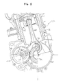
- FIG. 5 is a fragmentary longitudinal sectional view of an internal-combustion engine 101 to which the present invention is applied.
- a piston 102 is operatively connected to a connection rod 103 which is connected to a crankshaft 104.
- the large end of the connecting rod 103 is connected to a crankpin 106 on the crank web 105 of the crankshaft 104.
- a balance weight 107 is formed integrally with the crank web 105 opposite to the crankpin 106 with respect to the axis of the crankshaft 104.
- a balancing shaft 108 extends in parallel to the crankshaft 104.
- the balancing shaft 108 is provided with a balance weight 109.
- a driving gear 110 securely mounted on the crankshaft 104 and a driven gear 111 securely mounted on the balancing shaft 108 are operatively meshed to connect the crankshaft 104 and the balancing shaft 108.
- the driving gear 110 and the driven gear 111 have the same diameter and the same number of teeth. Therefore, the balancing shaft 108 rotates synchronously with the crankshaft 104 in a direction opposite the direction of rotation of the crankshaft 104 at the same angular velocity as that at which the crankshaft 104 rotates.
- the balance weight 107 is positioned opposite to the piston 102 with respect to the crankshaft 104 and the balance weight 109 is on the same side as the balance weight 107 with respect to the balancing shaft 108 when the piston 102 is at the top dead center.
- the balance weights 107 and 109 rotate together with the crankshaft 104 and the balancing shaft 108 in opposite directions, respectively, to counterbalance the inertial force of the reciprocating masses, i.e., the masses of the piston 102, the connecting rod 103 and such.
- the gears 110 and 111 are splined to the crankshaft 104 and the balancing shaft 108, respectively, and the gears 110 and 111 are provided with internal splines 113.
- One of the internal splines 113 of each of the gears 110 and 111 is removed to form a locating groove 114.
- the crankshaft 104 and the balancing shaft 108 are provided with external splines 115 that mate with the internal splines 113 of the gears 110 and 111, respectively.
- the two adjacent external splines 115 of each of the crankshaft 104 and the balancing shaft 108 are joined together to form a locating ridge 116 that fits the locating groove 114.
- the gears 110 and 111 can be put on the crankshaft 104 and the balancing shaft 108 only when the locating grooves 114 coincide with the locating ridges 116 of the crankshaft 104 and the balancing shaft 108, respectively.
- the angular positions of the gears 110 and 111 on the crankshaft 104 and the balancing shaft 108 are fixed.
- the respective angular positions of the driving gear 110 and the driven gear 111 on the crankshaft 104 and the balancing shaft 108 are determined by putting the driving gear 110 and the driven gear 111 on the crankshaft 104 and the balancing shaft 108 with the locating ridges 116 fitted in the corresponding locating grooves 114, respectively.
- Figure 6 shows a state where the balance weights 107 and 109 have been set at the angular positions shown in Figure 5 by turning the crankshaft 104 and the balancing shaft 108 together with the gears 110 and 111.
- a particular tooth 117a of the driving gear 110 and a particular tooth 117b of the driven gear 111 are meshed with each other.
- locating marks 118a and 118b on the particular teeth 117a and 117b coincide with each other.
- the driving gear 110 and the driven gear 111 are turned together with the crankshaft 104 and the balancing shaft 108 to mesh the tooth 117a marked with the locating mark 118a and the tooth 117b of the driven gear 111 marked with the locating mark 118b, to connect the crankshaft 104 and the balancing shaft 108 in a given angular relation.
- crankshaft 104 properly provided with the driving gear 110 at an angular position shown in Figure 5, to position the driven gear 111 with its tooth 117b in mesh with the tooth 117a of the driving gear 110, to set the balancing shaft 108 at an angular position where the positioning ridge 116 of the balancing shaft 108 is received in the locating groove 114 of the driven gear 111, and to mount the driven gear 111 on the balancing shaft 108.
- the locating marks 118a and 118h need not necessarily be marked on the teeth that are meshed when the piston 102 is at the top dead center and the balancing shaft 108 is at a corresponding angular position meeting the given angular relation between the crankshaft 104 and the balancing shaft 108 and may be marked on the teeth that are meshed when the piston 102 is at any position and the crankshaft 104 and the balancing shaft are in an angular relation corresponding to the given angular relation, the assembling work can more easily be carried out when the locating marks are marked on a tooth of the driving gear 110 and a tooth of the driven gear 111 that are in mesh when the balance weight 107 is at a position corresponding to the position of the piston 102 at the top dead center or the bottom dead center and the balance weight 107 is at a position corresponding to the position of the balance weight 107.
- the locating groove 114 of the driving gear 110 and the locating groove 114 of the driven gear 111 are substantially in a point-symmetrical relation with respect to the point P of engagement of the teeth 117a and 117b. That is, the locating grooves 114 are on a straight line passing the point P at equal distances from the point P, respectively.
- the locating marks 118a and 118b are short lines that are aligned with each other when a point on the tooth surface of the particular tooth 117a corresponding to the middle point between the tip 119 and the root 120 of the particular tooth 117a and a point on the tooth surface of the particular tooth 117b corresponding to the middle point between the tip 119 and the root 120 of the particular tooth 117b are in contact with each other.
- the driving gear 110 and the driven gear 111 are perfectly identical with each other, which will readily be understood if the driven gear 111 is turned through an angle of 180 from the position shown in Figure 6 and superposed on the driving gear 110.
- the balancing shaft driving mechanism is provided with the driving gear and the driven gear which are perfectly identical with each other. Therefore, only a single kind of gear must be kept in stock, which is advantageous to parts management and assembling work. Furthermore, the driving gear and the driven gear are never mounted on the crankshaft and the balancing shaft, respectively, in a wrong arrangement.
Landscapes
- Engineering & Computer Science (AREA)
- General Engineering & Computer Science (AREA)
- Mechanical Engineering (AREA)
- Physics & Mathematics (AREA)
- Acoustics & Sound (AREA)
- Aviation & Aerospace Engineering (AREA)
- Chemical & Material Sciences (AREA)
- Combustion & Propulsion (AREA)
- Shafts, Cranks, Connecting Bars, And Related Bearings (AREA)
- Gear Transmission (AREA)
Applications Claiming Priority (4)
| Application Number | Priority Date | Filing Date | Title |
|---|---|---|---|
| JP51668/93U | 1993-08-30 | ||
| JP23740693A JP3396514B2 (ja) | 1993-08-30 | 1993-08-30 | 内燃機関のバランサ軸駆動装置 |
| JP1993051668U JP2592999Y2 (ja) | 1993-08-30 | 1993-08-30 | 内燃機関のバランサ装置 |
| JP237406/93 | 1993-08-30 |
Publications (3)
| Publication Number | Publication Date |
|---|---|
| EP0640776A2 true EP0640776A2 (fr) | 1995-03-01 |
| EP0640776A3 EP0640776A3 (fr) | 1995-08-09 |
| EP0640776B1 EP0640776B1 (fr) | 1998-04-29 |
Family
ID=26392221
Family Applications (1)
| Application Number | Title | Priority Date | Filing Date |
|---|---|---|---|
| EP19940113532 Expired - Lifetime EP0640776B1 (fr) | 1993-08-30 | 1994-08-30 | Mécanisme d'équilibrage pour moteur à combustion interne |
Country Status (2)
| Country | Link |
|---|---|
| EP (1) | EP0640776B1 (fr) |
| DE (1) | DE69409888T2 (fr) |
Cited By (3)
| Publication number | Priority date | Publication date | Assignee | Title |
|---|---|---|---|---|
| DE10032095A1 (de) * | 2000-07-01 | 2002-01-17 | Porsche Ag | Kurbeltrieb für eine Brennkraftmaschine |
| EP1739323A1 (fr) * | 2005-06-27 | 2007-01-03 | Aisin Seiki Kabushiki Kaisha | Dispositif d'équilibrage pour un moteur à combustion |
| JP2014095327A (ja) * | 2012-11-08 | 2014-05-22 | Mitsubishi Heavy Ind Ltd | エンジンのギヤケース装置 |
Families Citing this family (1)
| Publication number | Priority date | Publication date | Assignee | Title |
|---|---|---|---|---|
| DE102006033975A1 (de) * | 2006-07-22 | 2008-01-24 | Dr.Ing.H.C. F. Porsche Ag | Anordnung einer Kurbelwelle in einem Kurbelgehäuse einer Brennkraftmaschine |
Family Cites Families (9)
| Publication number | Priority date | Publication date | Assignee | Title |
|---|---|---|---|---|
| US1691408A (en) * | 1927-03-18 | 1928-11-13 | Palmer Walter Tuttle | Timing device |
| JPS57161333A (en) * | 1981-03-27 | 1982-10-04 | Yamaha Motor Co Ltd | Multi-cylinder internal combustion engine |
| JPS57195944A (en) * | 1981-05-29 | 1982-12-01 | Yamaha Motor Co Ltd | Balancer device of internal combustion engine |
| JPS5837344A (ja) * | 1981-08-31 | 1983-03-04 | Fuji Heavy Ind Ltd | 3気筒エンジンのバランサ装置 |
| JPS6010691A (ja) * | 1983-06-29 | 1985-01-19 | 日本電気ホームエレクトロニクス株式会社 | チツプ部品取付方法 |
| US4688313A (en) * | 1985-12-30 | 1987-08-25 | Keller John E | Method and apparatus for removing and installing a partially fibrous camshaft gear |
| JP2540109B2 (ja) * | 1986-03-05 | 1996-10-02 | マツダ株式会社 | エンジンのバランサシヤフト |
| DE4008455C2 (de) * | 1990-03-16 | 1995-06-01 | Kloeckner Humboldt Deutz Ag | Montageverfahren und Montagevorrichtung für eine Hubkolbenbrennkraftmaschine |
| US5064040A (en) * | 1991-02-14 | 1991-11-12 | Deere & Company | Splined clutch drum mounting |
-
1994
- 1994-08-30 EP EP19940113532 patent/EP0640776B1/fr not_active Expired - Lifetime
- 1994-08-30 DE DE1994609888 patent/DE69409888T2/de not_active Expired - Fee Related
Cited By (5)
| Publication number | Priority date | Publication date | Assignee | Title |
|---|---|---|---|---|
| DE10032095A1 (de) * | 2000-07-01 | 2002-01-17 | Porsche Ag | Kurbeltrieb für eine Brennkraftmaschine |
| US6659060B2 (en) | 2000-07-01 | 2003-12-09 | Harley-Davidson Motor Company Group, Inc. | Crankshaft drive for an internal-combustion engine |
| DE10032095B4 (de) * | 2000-07-01 | 2005-06-23 | Dr.Ing.H.C. F. Porsche Ag | Kurbeltrieb für eine Brennkraftmaschine |
| EP1739323A1 (fr) * | 2005-06-27 | 2007-01-03 | Aisin Seiki Kabushiki Kaisha | Dispositif d'équilibrage pour un moteur à combustion |
| JP2014095327A (ja) * | 2012-11-08 | 2014-05-22 | Mitsubishi Heavy Ind Ltd | エンジンのギヤケース装置 |
Also Published As
| Publication number | Publication date |
|---|---|
| DE69409888T2 (de) | 1998-08-27 |
| EP0640776A3 (fr) | 1995-08-09 |
| EP0640776B1 (fr) | 1998-04-29 |
| DE69409888D1 (de) | 1998-06-04 |
Similar Documents
| Publication | Publication Date | Title |
|---|---|---|
| EP0846849B1 (fr) | Moteur a combustion interne a pistons alternatifs, vilebrequin et a double coulisse circulaire | |
| US4440123A (en) | Half speed balancer | |
| US4966042A (en) | Balanced reciprocating machines | |
| JPH0249422B2 (fr) | ||
| EP0234846B1 (fr) | Dispositif d'équilibrage pour moteur à combustion interne | |
| US8047176B2 (en) | Balancer apparatus for an engine | |
| US5873339A (en) | Bidirectionally reciprocating piston engine | |
| US5960761A (en) | Engine with balancer device for vehicle | |
| JPH0221045A (ja) | 内燃機関のバランサ装置 | |
| EP0640776B1 (fr) | Mécanisme d'équilibrage pour moteur à combustion interne | |
| US6997073B2 (en) | Vehicle power unit | |
| US5156068A (en) | Bearing means for compensating masses | |
| US7021268B1 (en) | Crankshaft with airflow inducing surfaces | |
| GB2314888A (en) | Engine with balancers for a vehicle | |
| JPS6121445A (ja) | 一次の質量平衡を備えた内燃機関 | |
| US7434560B2 (en) | Balancing device for an engine | |
| GB2088481A (en) | Balancing mechanism in a four cylinder internal combustion engine | |
| US5564379A (en) | Arrangement for balancing varying moments | |
| JPH0718349B2 (ja) | 内燃機関の巻掛伝動装置 | |
| KR20060126523A (ko) | 통합형 밸런스 샤프트를 갖는 피스톤 엔진 | |
| US7159558B2 (en) | Engine having centralized mass | |
| US20050058553A1 (en) | Connection structure between a plastic gear and a support shaft, oil pump including the connection structure, and engine incorporating same | |
| JPS5936759Y2 (ja) | 4サイクル直列2シリンダエンジンの1次パランサ装置 | |
| JPH0771532A (ja) | 内燃機関のバランサ軸駆動装置 | |
| JPH0334510Y2 (fr) |
Legal Events
| Date | Code | Title | Description |
|---|---|---|---|
| PUAI | Public reference made under article 153(3) epc to a published international application that has entered the european phase |
Free format text: ORIGINAL CODE: 0009012 |
|
| AK | Designated contracting states |
Kind code of ref document: A2 Designated state(s): DE FR |
|
| PUAL | Search report despatched |
Free format text: ORIGINAL CODE: 0009013 |
|
| AK | Designated contracting states |
Kind code of ref document: A3 Designated state(s): DE FR |
|
| 17P | Request for examination filed |
Effective date: 19950824 |
|
| 17Q | First examination report despatched |
Effective date: 19960926 |
|
| GRAG | Despatch of communication of intention to grant |
Free format text: ORIGINAL CODE: EPIDOS AGRA |
|
| GRAG | Despatch of communication of intention to grant |
Free format text: ORIGINAL CODE: EPIDOS AGRA |
|
| GRAH | Despatch of communication of intention to grant a patent |
Free format text: ORIGINAL CODE: EPIDOS IGRA |
|
| GRAH | Despatch of communication of intention to grant a patent |
Free format text: ORIGINAL CODE: EPIDOS IGRA |
|
| GRAA | (expected) grant |
Free format text: ORIGINAL CODE: 0009210 |
|
| AK | Designated contracting states |
Kind code of ref document: B1 Designated state(s): DE FR |
|
| REF | Corresponds to: |
Ref document number: 69409888 Country of ref document: DE Date of ref document: 19980604 |
|
| ET | Fr: translation filed | ||
| PLBE | No opposition filed within time limit |
Free format text: ORIGINAL CODE: 0009261 |
|
| STAA | Information on the status of an ep patent application or granted ep patent |
Free format text: STATUS: NO OPPOSITION FILED WITHIN TIME LIMIT |
|
| 26N | No opposition filed | ||
| PGFP | Annual fee paid to national office [announced via postgrant information from national office to epo] |
Ref country code: DE Payment date: 20070823 Year of fee payment: 14 |
|
| PGFP | Annual fee paid to national office [announced via postgrant information from national office to epo] |
Ref country code: FR Payment date: 20070808 Year of fee payment: 14 |
|
| REG | Reference to a national code |
Ref country code: FR Ref legal event code: ST Effective date: 20090430 |
|
| PG25 | Lapsed in a contracting state [announced via postgrant information from national office to epo] |
Ref country code: FR Free format text: LAPSE BECAUSE OF NON-PAYMENT OF DUE FEES Effective date: 20080901 Ref country code: DE Free format text: LAPSE BECAUSE OF NON-PAYMENT OF DUE FEES Effective date: 20090303 |