EP0640819B1 - Hochtemperaturdruckfühler mit drei Faserlichtleitern unterschiedlicher numerischer Apertur - Google Patents
Hochtemperaturdruckfühler mit drei Faserlichtleitern unterschiedlicher numerischer Apertur Download PDFInfo
- Publication number
- EP0640819B1 EP0640819B1 EP94112912A EP94112912A EP0640819B1 EP 0640819 B1 EP0640819 B1 EP 0640819B1 EP 94112912 A EP94112912 A EP 94112912A EP 94112912 A EP94112912 A EP 94112912A EP 0640819 B1 EP0640819 B1 EP 0640819B1
- Authority
- EP
- European Patent Office
- Prior art keywords
- sensor
- optical fiber
- disc
- fibers
- diaphragm
- Prior art date
- Legal status (The legal status is an assumption and is not a legal conclusion. Google has not performed a legal analysis and makes no representation as to the accuracy of the status listed.)
- Expired - Lifetime
Links
Images




Classifications
-
- G—PHYSICS
- G01—MEASURING; TESTING
- G01L—MEASURING FORCE, STRESS, TORQUE, WORK, MECHANICAL POWER, MECHANICAL EFFICIENCY, OR FLUID PRESSURE
- G01L11/00—Measuring steady or quasi-steady pressure of a fluid or a fluent solid material by means not provided for in group G01L7/00 or G01L9/00
- G01L11/02—Measuring steady or quasi-steady pressure of a fluid or a fluent solid material by means not provided for in group G01L7/00 or G01L9/00 by optical means
- G01L11/025—Measuring steady or quasi-steady pressure of a fluid or a fluent solid material by means not provided for in group G01L7/00 or G01L9/00 by optical means using a pressure-sensitive optical fibre
-
- G—PHYSICS
- G01—MEASURING; TESTING
- G01L—MEASURING FORCE, STRESS, TORQUE, WORK, MECHANICAL POWER, MECHANICAL EFFICIENCY, OR FLUID PRESSURE
- G01L9/00—Measuring steady of quasi-steady pressure of fluid or fluent solid material by electric or magnetic pressure-sensitive elements; Transmitting or indicating the displacement of mechanical pressure-sensitive elements, used to measure the steady or quasi-steady pressure of a fluid or fluent solid material, by electric or magnetic means
- G01L9/0041—Transmitting or indicating the displacement of flexible diaphragms
- G01L9/0076—Transmitting or indicating the displacement of flexible diaphragms using photoelectric means
- G01L9/0077—Transmitting or indicating the displacement of flexible diaphragms using photoelectric means for measuring reflected light
-
- G—PHYSICS
- G01—MEASURING; TESTING
- G01B—MEASURING LENGTH, THICKNESS OR SIMILAR LINEAR DIMENSIONS; MEASURING ANGLES; MEASURING AREAS; MEASURING IRREGULARITIES OF SURFACES OR CONTOURS
- G01B11/00—Measuring arrangements characterised by the use of optical techniques
- G01B11/24—Measuring arrangements characterised by the use of optical techniques for measuring contours or curvatures
-
- G—PHYSICS
- G01—MEASURING; TESTING
- G01K—MEASURING TEMPERATURE; MEASURING QUANTITY OF HEAT; THERMALLY-SENSITIVE ELEMENTS NOT OTHERWISE PROVIDED FOR
- G01K11/00—Measuring temperature based upon physical or chemical changes not covered by groups G01K3/00, G01K5/00, G01K7/00 or G01K9/00
- G01K11/32—Measuring temperature based upon physical or chemical changes not covered by groups G01K3/00, G01K5/00, G01K7/00 or G01K9/00 using changes in transmittance, scattering or luminescence in optical fibres
-
- G—PHYSICS
- G01—MEASURING; TESTING
- G01L—MEASURING FORCE, STRESS, TORQUE, WORK, MECHANICAL POWER, MECHANICAL EFFICIENCY, OR FLUID PRESSURE
- G01L23/00—Devices or apparatus for measuring or indicating or recording rapid changes, such as oscillations, in the pressure of steam, gas, or liquid; Indicators for determining work or energy of steam, internal-combustion, or other fluid-pressure engines from the condition of the working fluid
- G01L23/08—Devices or apparatus for measuring or indicating or recording rapid changes, such as oscillations, in the pressure of steam, gas, or liquid; Indicators for determining work or energy of steam, internal-combustion, or other fluid-pressure engines from the condition of the working fluid operated electrically
- G01L23/16—Devices or apparatus for measuring or indicating or recording rapid changes, such as oscillations, in the pressure of steam, gas, or liquid; Indicators for determining work or energy of steam, internal-combustion, or other fluid-pressure engines from the condition of the working fluid operated electrically by photoelectric means
-
- G—PHYSICS
- G06—COMPUTING OR CALCULATING; COUNTING
- G06F—ELECTRIC DIGITAL DATA PROCESSING
- G06F17/00—Digital computing or data processing equipment or methods, specially adapted for specific functions
- G06F17/10—Complex mathematical operations
Definitions
- the present invention generally relates to the art of optoelectronic sensing, and more specifically to an improved fiber optic sensor for sensing the pressure in a high temperature, high pressure environment such as the combustion chamber of an internal combustion engine.
- U.S. Patent No. 4,799,751 entitled “DETECTION DEVICE USING FIBER OPTIC TECHNIQUES", issued Jan. 24, 1989 to V. Tekippe, discloses a pressure sensor such as illustrated in FIGS. 1a to 1c and 2 and designated as 10.
- the sensor 10 includes a flexible disc or diaphragm 12 having an upper first surface 12a which is exposed to a pressure to be sensed.
- Second and third outer optical fibers 16 and 18 are spaced on the opposite sides of the fiber 14. The fibers 14, 16 and 18 are parallel, at least at their upper end portions which are adjacent to the diaphragm 12.
- the center of the inner fiber 14 is spaced from the center of the diaphragm 12 by a distance x.
- the fiber 16 is radially inward of the fibers 14 and 18.
- x r/3 1/2 , where r is the radius of the diaphragm 12.
- r the radius of the diaphragm 12.
- the upper ends of the fibers 14, 16 and 18 are spaced from the surface 12b of the diaphragm 12 by a distance y and are perpendicular to the diaphragm 12 when the diaphragm 12 is flat.
- FIG. 1b illustrates the case in which the pressure P which is applied to the surface 12a of the diaphragm 12 is zero, and the diaphragm 12 is flat.
- FIG. 1a illustrates the pressure P as being greater than zero.
- the diaphragm 12 is curved by the applied pressure such that the surface 12b which faces the fibers 14, 16 and 18 is convex. Since the fibers 14, 16 and 18 are offset from the center of the diaphragm 12, more light is reflected from the surface 12b into the fiber 18 than into the fiber 16. In this case I IN ⁇ I OUT .
- the surface 12b of the diaphragm 12 which faces the fibers 14, 16 and 18 is concave, and more light is reflected from the surface 12b into the fiber 16 than into the fiber 18, such that I IN > I OUT .
- the sensor 10 is capable of sensing both the magnitude and sign (positive or negative) of the pressure P.
- the geometry of the sensor 10 for the exemplary case of negative pressure P is illustrated in FIG. 2.
- the fibers 14, 16 and 18 are identical, having the same diameter, index of refraction and numerical aperture.
- Light emerging from the fiber 14 at the critical angle ⁇ c is refracted in the air gap between the fibers 14, 16 and 18 and the diaphragm 12 and is incident on the surface 12b of the diaphragm 12 at an angle ⁇ .
- the sensed pressure P is therefore independent of the diameter of the fibers 14, 16 and 18, the distance y between the fibers 14, 16 and 18 and the diaphragm 12, the reflectance of the diaphragm 12, the intensity of the input light I O , and is therefore insensitive to environmental perturbations.
- Tekippe is subject to substantial optical signal noise caused by physical perturbation or bending of the fibers 14, 16 and 18. Bending of the fibers 14, 16 and 18 causes changes in the optical mode distribution of the light propagating therethrough, which in turn affects the intensities I IN and I OUT and thereby the value of P.
- A is a function of the Young's modulus and Poisson's ratio of the diaphragm 12, both of which are temperature dependent. This causes the sensitivity of the diaphragm 12 to vary with temperature, and produce inaccuracy in the sensed value of pressure P.
- a diaphragm 12 consisting of a simple disc as disclosed by Tekippe is subject to temperature induced curvature which also varies with temperature.
- the curvature of such a diaphragm 12 will change as the temperature increases or decreases, even if there is no change in pressure P. These effects cause zero drift in the pressure reading, and limit the attainable accuracy of the sensor 10 in a high temperature environment.
- a first surface of a diaphragm is exposed to high temperature gas in the combustion chamber of an internal combustion engine.
- the curvature of the diaphragm changes in response to the gas pressure.
- One center and two outer optical fibers are spaced along a radius of the diaphragm and have ends which face a second surface thereof.
- a light source injects light into the center fiber, which is displaced from the center of the diaphragm by a predetermined distance.
- the two outer fibers receive light from the center fiber after reflection from the diaphragm.
- the relative intensities of reflected light correspond to the curvature of the diaphragm and thereby to the pressure.
- the outer fibers have a larger numerical aperture than the center fiber, and the light source fully populates all of the optical modes of the center fiber to increase the optical coupling coefficient and reduce noise caused by physical perturbation of the fibers, such as vibration from an engine or bending during installation.
- the fibers preferably have a square cross-section to maximize linearity and dynamic range.
- a diaphragm holder which clamps the peripheral edge has a larger coefficient of thermal expansion than the diaphragm.
- the diaphragm is retained at its peripheral edge by a cylindrical member having low thermal mass which extends from the diaphragm holder.
- a computer computes pressure in response to the relative reflected light intensities.
- An engine temperature sensor which is standard equipment in automotive vehicles provides an input to the computer which enables compensation for variation of the sensitivity of the diaphragm with temperature.
- the present sensor is also insensitive to interference caused by electromagnetic radiation which is generated at high levels by the ignition system of an internal combustion engine.
- a fiber optic sensor 20 embodying the present invention is illustrated in FIGS. 3 to 6.
- the sensor 20 includes a metal body 22 which is threaded into a hole 24 which opens through a cylinder head 26 into a combustion chamber 32 of an internal combustion engine.
- the cylinder head 26 is bolted to a cylinder block 28 in which a piston 30 is reciprocated by combustion of an air-fuel mixture in the combustion chamber 32.
- a spark plug 34 is illustrated as extending into the combustion chamber 32 for igniting the air-fuel mixture therein.
- the sensor 20 includes first, second and third optical fibers 40, 42 and 44 which are retained by the body 22 and preferably have rectangular or square cross-sections as illustrated in FIG. 6.
- a diaphragm 46 in the form of a circular disc which is also retained by the body 22 has a first surface 46a which is exposed to a pressure P in the combustion chamber 32, and a second surface 46b which faces the adjacent ends of the fibers 40, 42 and 44.
- the fiber 42 is spaced radially inward from the fibers 40 and 44.
- the centers of the fibers 40, 42 and 44 are spaced from each other by a distance d (the width of each fiber 40, 42 and 44), such that the center of the fiber 42 is spaced by x-d from the center 48, and the center of the fiber 44 is spaced by x+d from the center 48.
- the ends of the fibers 40, 42 and 44 which face the surface 46b of the diaphragm 46 are perpendicular to the surface 46b, and spaced therefrom by a distance y when no force or pressure is applied to the diaphragm 46 and the diaphragm 46 is flat.
- a light source 50 such as a light emitting diode or a laser diode injects light into the fiber 40.
- Light from the fiber 40 is reflected from the surface 46b of the diaphragm 46 into the fibers 42 and 44 in a relative proportion which depends on the curvature of the diaphragm 46 in the manner described above with reference to FIGs. 1a to 1c and 2.
- the light from the fibers 42 and 44 is piped to photodetectors 52 and 54 respectively which produce electrical output signals (voltages or currents) having magnitudes I 1 and I 2 which correspond to the intensities I IN and I OUT respectively.
- An optional engine temperature sensor 58 is further illustrated which provides a temperature input to the computer 56 as will be described below. This temperature sensor can be used to compensate for temparture variations in A at the higher temperatures.
- I OUT and I IN may individually be sensitive to environmental perturbations such as vibration, bending of the fibers during installation and temperature changes, which can produce variations in the diameter of the fibers 40, 42 and 44, the distance y between the fibers 40, 42 and 44 and the diaphragm 46, the reflectance of the diaphragm 46 and the intensity of the input light I O from the light source 50, the expression (I OUT -I IN )/(I OUT +I IN ) is substantially insensitive to such perturbations. Since A is also substantially constant at the lower temperatures, the sensed pressure P (which depends upon I OUT , I IN and A) is also substantially independent of these perturbations at the lower temperatures.
- the distance y between the ends of the fibers 40, 42 and 44 and the diaphragm 46 can also be determined empirically by varying the distance y, and determining the value at which the maximum response to pressure variation is detected by the sensor 20.
- the optical fibers 40, 42 and 44 and light source 50 are designed such that substantially all optical modes of the fiber 40 are fully populated (mode scrambled). This substantially reduces the sensitivity of the sensor 20 to optical modal noise caused by physical perturbation of the fiber 40 resulting from variation of the optical mode distribution in the fiber 40 which is a problem in the prior art as discussed above. Techniques for fully populating the optical modes of an optical fiber are well known in the art per se.
- the optical noise in the fibers 40, 42 and 44 is further reduced in accordance with the invention by making the numerical aperture of the second and third fibers 42 and 44 larger than the numerical aperture of the first fiber 40. This increases the optical coupling between the fibers 40, 42 and 44, ensures that the reflected light propagating through the fibers 42 and 44 will not suffer any loss other than Fresnel reflection, and prevents distortion caused by optical signal loss.
- the numerical apertures of the fibers 42 and 44 are preferably the same, but can be different within the scope of the invention.
- the fibers 42 and 44 had the same numerical aperture as the first fiber 40 in the manner disclosed by Tekippe, it would be necessary to make the optical modes of the first fiber 40 less than fully populated in order to narrow the beam divergence and ensure that all reflected light enters the second and third fibers 44 and 46. This would increase the sensitivity of the sensor to physical perturbation and result in a change in the profile of the spot projected from the fiber 40 onto the diaphragm 46 which cannot be distinguished from the applied pressure.
- the numerical aperture of the fibers 42 and 44 is therefore made sufficiently larger than that of the fiber 40 to not merely to ensure that all reflected light is captured by the fibers 42 and 44, but also to ensure that the reflected light enters the fibers 42 and 44 at an angle that the critical angle will not be exceeded under all circumstances and the light will be strongly guided through the fibers 42 and 44. This positively precludes radiation loss through the fibers 42 and 44 and accompanying non-linearity and noises.
- the numerical apertures of the fibers 40, 42 and 44 are preferably selected in accordance with the following relations as shown in FIG. 7, in which the flexing of diaphragm 46 is exaggerated for purposes of illustration. ⁇ A ⁇ ⁇ B + ⁇ C + ⁇ D + ⁇ E, where
- the fibers 40, 42 and 44 can have the same or different physical cross-sectional-areas as long as the numerical aperture of the fibers 42 and 44 is larger than that of the fiber 40 as expressed above.
- the cross-section of the fiber 40 is made as small as possible for maximizing linearity by constraining the beam to a substantially linear area of the diaphragm 46, but not so small that the efficiency by which light is coupled into the fiber is insufficient.
- the cross-section of the fibers 42 and 44 is made as large as possible to maximize the light collection efficiency.
- the fibers 40, 42 and 44 have the same diameter.
- the fibers 40, 42 and 44 can be made of any suitable commercially available material such as glass, fused silica or sapphire. Regardless of the configuration of the fibers 40, 42 and 44, the cladding thickness thereof is made as small as possible to minimize dead space between the fibers 40, 42 and 44.
- the cross-sections of the fibers 40, 42 and 44 are preferably rectangular or square. The reason for this is illustrated in FIG. 8.
- Optical fibers 40', 42' and 44' correspond to the fibers 40, 42 and 44 respectively but have circular cross-sections.
- the light beam from the fiber 40' which is reflected from the diaphragm 46 onto the fibers 42' and 44' is subjected to divergence in the air gap therebetween and is designated as 60.
- the center of the beam 60 is illustrated as being deflected leftwardly from the center of the fiber 40' due to a negative pressure P in accordance with the principles described above with reference to FIG. 2.
- the light beams subtend areas 62 and 64 of the ends of the fibers 42' and 44' respectively as indicated by hatching.
- the areas 62 and 64 vary non-linearly in response to displacement of the beam 60 along a line joining the centers of the fibers 40', 42' and 44'.
- the response of a sensor including the three circular fibers 40', 42, and 44' is acceptably linear only with a predetermined range indicated by hatched areas 66 and 68.
- the edge of the beam 60 intersects the peripheral edges of the fibers 42' and 44' along diameters which are perpendicular to the line joining the centers of the fibers 40', 42' and 44'.
- the acceptable sizes of the areas 66 and 68 for pressures between a maximum negative value P - max and a maximum positive value P + max are relatively small as illustrated.
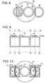
- FIG. 9 The preferred embodiment of the invention as utilizing rectangular or square fibers 40, 42 and 44 to overcome the drawback described with reference to FIG. 8 is illustrated in FIG. 9.
- the geometry of the sensor 20 is selected such that the vertical edges of a beam ABCD reflected back on the fibers 42 and 44 from the diaphragm 46 will pass through the centers of the fibers 42 and 44 as indicated at AD and BC respectively at zero pressure P 0 .
- the areas of the fibers 42 and 44 which are subtended by the light beam from the fiber 40 vary linearly for all values of pressure P between P + max and P - max.
- the sensor 20 therefore has a theoretically perfect linear response to pressure variation and maximum dynamic range.
- FIG. 10 Further illustrated in FIG. 10 is an arrangement including the square fibers 42 and 44 and the circular fiber 40'.
- the linearity of this configuration is slightly less than that of FIG. 9.
- FIGs. 11 and 12 illustrate a portion of the sensor 20 including the body 22 and the diaphragm 46.
- the body 22 is formed with a central bore 70 and a threaded, reduced diameter portion 72 which screws into the hole 24 in the cylinder head 26 as illustrated in FIG. 3.
- the bore 70 has an enlarged, internally threaded portion 74.
- the peripheral edge of the diaphragm 46 is clamped between a step defined at the bottom of the portion 74 and an annular setscrew 76 which screws into the portion 74.
- the optical fibers 40, 42 and 44 are not illustrated in FIG. 11, but intrude into the bore 70 such that their ends are adjacent to the surface 46b of the diaphragm 46.
- the surface 46a of the diaphragm 46 is exposed to the pressure in the combustion chamber 32.
- the body 22 and the setscrew 76 constitute a diaphragm holder 78 which has a much larger thermal mass than the diaphragm 46. Since the diaphragm holder 78 is connected to the engine block, which is cooled and constitutes a heat sink, the temperature of the diaphragm 46, which is exposed directly to the combustion gas, will be significantly higher than the temperature of the diaphragm holder 78.
- this temperature differential will cause the diaphragm and diaphragm holder to expand at different rates. In a simple arrangement such as disclosed by Tekippe, this will cause the curvature of the diaphragm to vary in response to changes in temperature, even if the applied pressure does not change. This thermally induced curvature varies with temperature, and causes zero level drift in the sensed pressure.
- the coefficient of thermal expansion of the diaphragm holder 78 is made larger than that of the diaphragm 46 by an amount which is selected in accordance with the anticipated operating temperature and temperature difference between the diaphragm 46 and the diaphragm holder 78.
- the design is preferably determined empirically. With proper selection, the diaphragm 46 will be flat at zero pressure, and the curvature of the diaphragm 46 will not change in response to temperature variation over the anticipated operating temperature range of the sensor 20.
- a suitable material for the diaphragm 46 is Inconel alloy 718 which has a thermal expansion coefficient of approximately 13 x 10 -6 /°C, and a high yield strength of greater than 130,000 psi at 700°C.
- a suitable material for the diaphragm holder 78 which is matched to the diaphragm material is series 300 stainless steel, having a thermal expansion coefficient of approximately 17 x 10 -6 /°C.
- the temperature of the diaphragm 46 can be reduced, and the temperature difference between the diaphragm 46 and the diaphragm holder 78 correspondingly reduced, by providing a perforated heat shield 80 in front of the surface 46a of the diaphragm 46.
- the heat shield 80 is made of copper or other high temperature and high thermal conductivity material which will not adversely adverse the pressure response of the diaphragm 46.
- the heat conduction between the diaphragm 46 and the diaphragm holder 78 can be improved by providing copper cladding on at least one of these elements.
- FIG. 13 illustrates another arrangement for inhibiting thermally induced curvature of the diaphragm 46.
- a diaphragm holder 82 includes a sensor body 84 which is formed with a central bore 86, and a hollow, cylindrical member 88 which is attached at its lower end to the body 84 and at its upper end to the periphery of the diaphragm 46.
- the member 88 has small thermal and mechanical mass and serves to insulate the diaphragm 46 from the diaphragm holder 82 and reduce the thermal expansion differential which causes thermally induced curvature.
- t 1 ⁇ t 2 ⁇ t 3 where t 1 is the thickness of the diaphragm 46, t 2 is the thickness of the cylindrical member 88 and t 3 is the thickness of a flange portion of the cylindrical member 88 which is welded to the body 84.
- FIG. 14 illustrates an alternative arrangement including a sensor body 90 which is formed with a central bore 92, and a hollow cylindrical member 94 which intrudes into the bore 92.
- This arrangement enables the threaded portion of the body 90 which screws into the hole 24 to be made longer, thereby increasing the efficiency by which the body 90 acts as a heat sink for the diaphragm 46.
- the relationship t 1 ⁇ t 2 ⁇ t 3 is also applicable to the embodiment of FIG. 14.
- FIG. 15 illustrates another arrangement for inhibiting thermally induced diaphragm curvature.
- a sensor body 100 which acts as a diaphragm holder is formed with a central bore 102.
- a diaphragm 104 includes a relatively hard main disc 106 which is retained at a step in the bore 102, a relatively soft secondary disc 108 which is sealingly attached to the upper end of the body 100, and a fluid 110 which fills the space between the discs 106 and 108.
- the fluid 110 is a synthetic oil or other material which has a high boiling point and low thermal conductivity and low compressivity.
- the disc 108 and fluid 110 thermally shield the disc 106, whose curvature is sensed for pressure measurement, from the heat in the combustion chamber 32 and thereby inhibit thermally induced curvature thereof.
- the secondary disc 108 is soft enough that it does not substantially affect the pressure which is transmitted by the disc 108 and fluid 110 to the main disc 106.
- FIG. 16 illustrates a sensor head assembly 120 which provides an improved level of insensitivity to physical perturbation of the center optical fiber 40 and minimize the optical loss if a connector is used between the cable and sensor head.
- the assembly 120 includes a hollow sensor body or probe 122 made of thermally resistant ceramic, metal, plastic or resin or the like.
- the optical fibers 40, 42 and 44 extend upwardly through the probe 122 from the lower end thereof as shown and are retained in the probe 122 by ceramic cement (not shown).
- the fibers 42 and 44 terminate at their upper ends in optical connectors 124 and 126, and are connected to the photodetectors 52 and 54 of FIG. 5 through optical fibers 128 and 130 of large diameter and large numerical aperture which plug into the connectors 124 and 126 respectively.
- the light source 50 is constituted by a light emitting diode or laser diode which is retained in the probe 122 by an electrically and thermally insulative ceramic cement, and is connected to inject light into the upper end of the fiber 40.
- the light source 50 is powered through electrical leads 132 and 134 which terminate in electrical connectors 136 and 138 respectively. Electrical leads 140 and 142 plug into the connectors 136 and 138 respectively and are connected to an appropriate electrical power source (not shown).
- the assembly 120 is provided with adequate thermal insulation (not shown) to maintain it below the cooling water temperature of the engine block and thereby below the maximum operating temperature of the light source 50, which is typically 130°C for a light emitting diode. Any electrical interference on the electrical leads 140 and 142 has negligible effect on the optical pressure signal propagating through the optical fibers 128 and 130 with the photodetectors 52 and 54 located remotely from the engine block.
- the optical pressure signal propagating through the fibers 128 and 130 is only sensitive to power loss therein, and is not affected by optical mode distribution profile change.
- the optical power loss in the fibers 128 and 130, even under severe operating conditions, is minimal due to their large numerical aperture.
- the optical fibers 40, 42 and 44 are preferably made of high quality optical glass in order to provide the required high temperature environment
- the fibers 128 and 132 can be made of low cost plastic due to their large numerical aperture. This enables the assembly 120 to be manufactured at low cost on a commercial production basis.
- the value of A is not constant, but varies as a function of temperature. This, in addition to the temperature difference ⁇ T between the diaphragm and the diaphragm holder, creates zero drift in the computed value of pressure P and thereby inaccuracy in the operation of the sensor.
- the A.C. and D.C. components of (I OUT -I IN )/(I OUT +I IN ) can be separated by bandpass filters in a conventional manner.
- A Cr 3 (1- ⁇ 2 ) 3.45 n 1 Yt 3 tan ⁇ c
- C Cr 3 (1- ⁇ 2 ) 3.45 n 1 Yt 3 tan ⁇ c
- C Cr 3 (1- ⁇ 2 ) 3.45 n 1 Yt 3 tan ⁇ c
- C Cr 3 (1- ⁇ 2 ) 3.45 n 1 Yt 3 tan ⁇ c
- C Cr 3 (1- ⁇ 2 ) 3.45 n 1 Yt 3 tan ⁇ c
- C Cr 3 (1- ⁇ 2 ) 3.45 n 1 Yt 3 tan ⁇ c
- the engine temperature sensor which is conventionally provided for an internal combustion engine can bifunction as the sensor 58, thereby eliminating the need for a separate temperature sensor.
- This arrangement enables the computer 50 to compute the pressure as a predetermined function of I IN , I OUT and temperature with a high degree of accuracy, even at high temperatures at which the sensitivity of the diaphragm varies significantly with temperature.
- a sensor 20 embodying the present invention was constructed and tested on an LT-1 Corvette engine under motoring conditions at 130°C (no combustion), and firing conditions at over 700°C (full combustion). The sensitivity and linearity were comparable to those of an instrumentation grade acoustic sensor without significant thermal effects.
- the sensor 20 included a center fiber 40 having a circular cross-section made of silica with a core diameter of 200 micrometers, a cladding outer diameter of 250 micrometers and a numerical aperture of 0.22.
- the outer fibers 42 and 44 also had circular cross-sections, a core diameter of 200 micrometers, a cladding outer diameter of 250 micrometers and a numerical aperture of 0.56.
- the diaphragm 46 was made of 400 series stainless steel, and the diaphragm holder 78 was made of 300 series stainless steel.
- the sensor 20 was calibrated, and shipped to a remote location for testing without recalibration.
- the sensor 20 operated accurately with a few percent of zero drift, with the sensitivity and linearity substantially unchanged.
- the physical perturbation induced noise was approximately two orders of magnitude smaller than a similarly constructed sensor including three optical fibers having the same numerical aperture.
- the present sensor has been described as being especially suitable for a high temperature application such as sensing the pressure in the combustion chamber of an internal combustion engine
- the present sensor and diaphragm assembly can be advantageously employed in any application in which the curvature of a disc or other object is to be sensed.
- the present sensor can be used to provide either absolute or relative pressure readings in a variety of environments.
Landscapes
- Physics & Mathematics (AREA)
- General Physics & Mathematics (AREA)
- Engineering & Computer Science (AREA)
- Chemical & Material Sciences (AREA)
- Combustion & Propulsion (AREA)
- Theoretical Computer Science (AREA)
- Mathematical Physics (AREA)
- Data Mining & Analysis (AREA)
- Mathematical Analysis (AREA)
- Mathematical Optimization (AREA)
- Computational Mathematics (AREA)
- Pure & Applied Mathematics (AREA)
- Databases & Information Systems (AREA)
- Software Systems (AREA)
- General Engineering & Computer Science (AREA)
- Algebra (AREA)
- Measuring Fluid Pressure (AREA)
- Light Guides In General And Applications Therefor (AREA)
Claims (13)
- Ein Sensor (20) zur Erfassung der Krümmung einer Scheibe (46) mit:dadurch gekennzeichnet, daß die zweite und die dritte optische Faser (44, 46) numerische Apparaturen aufweisen, die größer als die numerische Apparatur der ersten optischen Faser (40) sind.einer ersten optischen Faser (40) zur Übertragung von Licht zu der Scheibe (46);einer zweiten optischen Faser (42), die auf einer Seite der ersten optischen Faser (40) angeordnet ist, um Licht von der ersten optischen Faser (40) nach der Reflexion von der Scheibe (46) zu erhalten undeiner dritten optischen Faser (44), die auf einer gegenüberliegenden Seite der ersten optischen Faser (40) angeordnet ist, um Licht von der ersten optischen Faser (40) nach der Reflexion von der Scheibe (46) zu erhalten;
- Sensor (20) nach Anspruch 1, dadurch gekennzeichnet, daß die erste, zweite und dritte optische Faser (40, 42, 44) entlang eines Radius der Scheibe (46) angeordnet sind, wobei die Mitte der ersten optischen Faser (40) von der Mitte (48) der Scheibe um einen vorbestimmten Abstand (x) beabstandet ist.
- Sensor (20) nach Anspruch 2, dadurch gekennzeichnet, daß x=r/3½, wobei x der vorbestimmte Abstand ist und r der Radius der Scheibe (46) ist.
- Sensor nach irgendeinem der Ansprüche 1 bis 3, dadurch gekennzeichnet, daß die erste, zweite und dritte optische Faser (40, 42, 44) Endbereiche aufweisen, die sich parallel zu jeder anderen erstrecken und in Enden enden, die von der Scheibe (46) um einen vorbestimmten Abstand (y) entfernt sind.
- Sensor (20) nach irgendeinem der Ansprüche 1 bis 4, dadurch gekennzeichnet, daßA die numerische Apparatur der zweiten und dritten optischen Faser (42, 44) ist;B die numerische Apparatur der ersten optischen Faser (40) ist;C eine vorbestimmte maximale Krümmung der Scheibe (46) in der Abwesenheit einer angelegten Kraft (P) ist;D eine vorbestimmte Krümmung der Scheibe (46) als Reaktion auf eine vorbestimmte maximale angelegte Kraft P ist undE eine vorbestimmte maximale induzierte Divergenz als Reaktion auf die physikalische Perturbation von Licht ist, das sich durch die erste optische Faser (40) ausbreitet.
- Sensor (20) nach irgendeinem der Ansprüche 1 bis 5, dadurch gekennzeichnet, daß er ferner eine Lichtquelle (50) aufweist, um Licht in die erste optische Faser (40) zu injizieren, derart, daß im wesentlichen alle optischen Moden der ersten optischen Faser (40) vollständig ausgefüllt sind.
- Sensor (20) nach irgendeinem der Ansprüche 1 bis 6, dadurch gekennzeichnet, daß die zweite und dritte optische Faser (42, 44) rechteckige Querschnitte aufweisen.
- Sensor (20) nach irgendeinem der Ansprüche 1 bis 7, dadurch gekennzeichnet, daß die erste optische Faser (40) einen rechteckigen Querschnitt oder einen kreisförmigen Querschnitt aufweist.
- Sensor (20) nach irgendeinem der Ansprüche 1 bis 8, dadurch gekennzeichnet, daß die erste, zweite und dritte optische Faser (40, 42, 44) relativ zu der Scheibe (46) derart angeordnet sind, daß Licht aus der ersten optischen Faser (40) von der Scheibe (46) auf die zweite und dritte optische Faser (44, 46) derart reflektiert wird, daß in der Abwesenheit von einer auf die Scheibe (46) ausgeübten Kraft (P) Kanten des reflektierten Lichtes im wesentlichen durch die Mitte der zweiten bzw. der dritten optischen Faser (44, 46) gelangen.
- Sensor (20) nach irgendeinem der Ansprüche 1 bis 9, dadurch gekennzeichnet, daß die Scheibe (46) ein Diafragma (46) mit einer ersten Oberfläche (46b) aufweist, die der ersten, zweiten und dritten optischen Faser (40, 42, 44) zugewandt ist, sowie eine zweite Fläche (46a), die der Kraft (P) ausgesetzt ist, die erfaßt werden soll.
- Sensor (20) nach irgendeinem der Ansprüche 1 bis 10, dadurch gekennzeichnet, daß er aufweist:einen ersten Fotodetektor (52) zur Aufnahme von Licht, das diesem von der zweiten optischen Faser (42) übertragen wird, und zum Erzeugen eines diesem entsprechenden ersten elektrischen Signals (I1);einen zweiten Fotodetektor (54) zur Aufnahme von Licht, das diesem von der dritten optischen Faser (44) übertragen wird und zum Erzeugen eines diesem entsprechenden zweiten elektrischen Signals (I2) undeinen Computer (56) zum Berechnen der Krümmung der Scheibe (46) als eine vorbestimmte Funktion des ersten und des zweiten elektrischen Signals (I1, I2).
- Sensor (20) nach irgendeinem der vorhergehenden Ansprüche mit:einem Körper (122), der die erste optische Faser (40) bzw. die zweite und dritte optische Faser (42, 44) auf gegenüberliegenden Seiten der ersten optischen Faser (40) festhält;einer Lichtquelle (50), die von dem Körper (122) gehalten ist, um Licht in ein Ende der ersten optischen Faser (40) zu injizieren;einem elektrischen Verbinder (136, 138), der von dem Körper (122) gehalten ist und mit der Lichtquelle (50) verbunden ist understen und zweiten optischen Verbindern (124, 126), die von dem Körper (122) gehalten sind und mit Enden der zweiten bzw. dritten optischen Faser (42, 44) verbunden sind.
- Sensor (20) nach Anspruch 12, dadurch gekennzeichnet, daß die Lichtquelle (50) eine lichtemittierende Diode umfaßt.
Priority Applications (1)
| Application Number | Priority Date | Filing Date | Title |
|---|---|---|---|
| EP00107198A EP1026493A3 (de) | 1993-08-27 | 1994-08-19 | Hochtemperaturdruckfühler mit Faserlichtleiter |
Applications Claiming Priority (2)
| Application Number | Priority Date | Filing Date | Title |
|---|---|---|---|
| US08/113,537 US5446279A (en) | 1993-08-27 | 1993-08-27 | Fiber optic sensor sensing curvature of a diaphragm |
| US113537 | 1993-08-27 |
Related Child Applications (1)
| Application Number | Title | Priority Date | Filing Date |
|---|---|---|---|
| EP00107198A Division EP1026493A3 (de) | 1993-08-27 | 1994-08-19 | Hochtemperaturdruckfühler mit Faserlichtleiter |
Publications (3)
| Publication Number | Publication Date |
|---|---|
| EP0640819A2 EP0640819A2 (de) | 1995-03-01 |
| EP0640819A3 EP0640819A3 (de) | 1996-11-27 |
| EP0640819B1 true EP0640819B1 (de) | 2002-09-25 |
Family
ID=22350007
Family Applications (2)
| Application Number | Title | Priority Date | Filing Date |
|---|---|---|---|
| EP94112912A Expired - Lifetime EP0640819B1 (de) | 1993-08-27 | 1994-08-19 | Hochtemperaturdruckfühler mit drei Faserlichtleitern unterschiedlicher numerischer Apertur |
| EP00107198A Withdrawn EP1026493A3 (de) | 1993-08-27 | 1994-08-19 | Hochtemperaturdruckfühler mit Faserlichtleiter |
Family Applications After (1)
| Application Number | Title | Priority Date | Filing Date |
|---|---|---|---|
| EP00107198A Withdrawn EP1026493A3 (de) | 1993-08-27 | 1994-08-19 | Hochtemperaturdruckfühler mit Faserlichtleiter |
Country Status (6)
| Country | Link |
|---|---|
| US (1) | US5446279A (de) |
| EP (2) | EP0640819B1 (de) |
| JP (1) | JPH07151624A (de) |
| KR (1) | KR950006437A (de) |
| CA (1) | CA2130652C (de) |
| DE (1) | DE69431421T2 (de) |
Families Citing this family (39)
| Publication number | Priority date | Publication date | Assignee | Title |
|---|---|---|---|---|
| US5714680A (en) * | 1993-11-04 | 1998-02-03 | The Texas A&M University System | Method and apparatus for measuring pressure with fiber optics |
| US5940547A (en) * | 1995-03-30 | 1999-08-17 | Klockner-Moeller Gmbh | Optical fiber accidental arc detector for an electric power distribution switching device |
| US5689107A (en) * | 1995-09-01 | 1997-11-18 | Hughes Aircraft Company | Displacement-based opto-electronic accelerometer and pressure sensor |
| US5763769A (en) * | 1995-10-16 | 1998-06-09 | Kluzner; Michael | Fiber optic misfire, knock and LPP detector for internal combustion engines |
| US5956447A (en) * | 1996-05-07 | 1999-09-21 | Univ Central Florida | Device and method for image acquisition through multi-mode fiber |
| US5706372A (en) * | 1996-08-12 | 1998-01-06 | Delco Electronics Corporation | Integrated optoelectronic combustion pressure sensor |
| AU7519296A (en) * | 1996-10-23 | 1998-05-15 | Optrand, Inc. | Integrated fiber optic combustion pressure sensor |
| DE69733279T2 (de) * | 1997-02-06 | 2006-01-19 | Optrand, Inc., Plymouth | Kraftstoffeinspritzeinheiten mit integrierten faseroptischen drucksensoren und zugeordnete kompensations-und uberwachungsvorrichtungen |
| JPH11173937A (ja) * | 1997-12-15 | 1999-07-02 | Hitachi Ltd | 車載用光ファイバ式筒内圧センサ |
| US5923809A (en) * | 1998-02-02 | 1999-07-13 | The United States Of America As Represented By The Administrator Of The National Aeronautics And Space Administration | Optical power source derived from engine combustion chambers |
| US6125218A (en) * | 1998-03-19 | 2000-09-26 | Humphrey; Ashley C. | Fiber optic pressure sensitive optical switch and apparatus incorporating same |
| US6758086B2 (en) * | 2001-06-08 | 2004-07-06 | Marek T. Wlodarczyk | Automotive cylinder pressure sensors |
| DE50208855D1 (de) * | 2001-08-16 | 2007-01-11 | Adz Nagano Gmbh | Optische vorrichtung zum messen des druckes oder der kraft |
| CA2411638A1 (en) * | 2002-11-12 | 2004-05-12 | Photon Control Inc. | Fiber optic sensing system |
| DE10312491B3 (de) * | 2003-03-20 | 2005-02-03 | Robert Bosch Gmbh | Drucksensor mit Hitzeschild zum Einsatz in Verbrennungskraftmaschinen |
| WO2004113983A1 (en) * | 2003-06-26 | 2004-12-29 | Lg Cable Ltd. | Apparatus for installing an optical fiber unit including a controller for controlling critical displacement of buckling and installation method using the same |
| US7104141B2 (en) * | 2003-09-04 | 2006-09-12 | Baker Hughes Incorporated | Optical sensor with co-located pressure and temperature sensors |
| US7191660B2 (en) * | 2004-04-15 | 2007-03-20 | Davidson Instruments Inc. | Flame shield for high temperature pressure transducer |
| JP2007033075A (ja) * | 2005-07-22 | 2007-02-08 | Jfe Advantech Co Ltd | 光学式水位計 |
| US7299700B2 (en) * | 2005-10-04 | 2007-11-27 | General Electric Company | Methods and apparatus for sensing pressure |
| US7409867B2 (en) * | 2006-05-23 | 2008-08-12 | Rosemount Inc. | Pressure sensor using light source |
| US7954383B2 (en) | 2008-12-03 | 2011-06-07 | Rosemount Inc. | Method and apparatus for pressure measurement using fill tube |
| US8327713B2 (en) | 2008-12-03 | 2012-12-11 | Rosemount Inc. | Method and apparatus for pressure measurement using magnetic property |
| US7870791B2 (en) | 2008-12-03 | 2011-01-18 | Rosemount Inc. | Method and apparatus for pressure measurement using quartz crystal |
| US7966887B2 (en) | 2009-03-26 | 2011-06-28 | General Electric Company | High temperature optical pressure sensor and method of fabrication of the same |
| GB2472437A (en) * | 2009-08-06 | 2011-02-09 | Vestas Wind Sys As | Wind turbine rotor blade control based on detecting turbulence |
| DE102010029818B4 (de) | 2010-06-08 | 2022-08-18 | Fraunhofer-Gesellschaft zur Förderung der angewandten Forschung e.V. | Positionssensor |
| US8132464B2 (en) | 2010-07-12 | 2012-03-13 | Rosemount Inc. | Differential pressure transmitter with complimentary dual absolute pressure sensors |
| DE102010037403B4 (de) * | 2010-09-08 | 2013-08-14 | CiS Forschungsinstitut für Mikrosensorik und Photovoltaik GmbH | Anordnung zur Messung von Verbiegungen |
| US9510786B2 (en) * | 2011-06-22 | 2016-12-06 | Biosense Webster (Israel) Ltd. | Optical pressure measurement |
| US8752433B2 (en) | 2012-06-19 | 2014-06-17 | Rosemount Inc. | Differential pressure transmitter with pressure sensor |
| US10823592B2 (en) | 2013-09-26 | 2020-11-03 | Rosemount Inc. | Process device with process variable measurement using image capture device |
| JP6233707B2 (ja) * | 2014-03-04 | 2017-11-22 | 東京エレクトロン株式会社 | 光学式温度センサ及び光学式温度センサの製造方法 |
| WO2017175314A1 (ja) * | 2016-04-05 | 2017-10-12 | オリンパス株式会社 | 湾曲情報導出装置及び内視鏡システム |
| WO2019055642A2 (en) * | 2017-09-14 | 2019-03-21 | Rosemount Inc | COMPACT SENSOR CONNECTOR FOR SINGLE-USE FLUID MEASUREMENT |
| JP7630121B2 (ja) * | 2018-11-29 | 2025-02-17 | 大日本印刷株式会社 | 圧電積層体及び圧電素子 |
| KR20220036777A (ko) * | 2020-09-16 | 2022-03-23 | 주식회사 엘티전자 | 유연 발광섬유를 이용한 직물 조명장치 |
| EP3995802B1 (de) * | 2020-11-05 | 2024-10-23 | Melexis Technologies NV | Doppeldrucksensor |
| CN113959375B (zh) * | 2021-08-25 | 2023-07-07 | 广东技术师范大学 | 一种塔筒法兰平面度检测装备的图像采集方法 |
Family Cites Families (35)
| Publication number | Priority date | Publication date | Assignee | Title |
|---|---|---|---|---|
| US3327584A (en) * | 1963-09-09 | 1967-06-27 | Mechanical Tech Inc | Fiber optic proximity probe |
| US3580082A (en) * | 1969-11-07 | 1971-05-25 | Bendix Corp | Pressure transducer |
| US3792928A (en) * | 1972-02-28 | 1974-02-19 | Schlumberger Compteurs | Fiber optics distance converting technique |
| DE2450080A1 (de) * | 1974-10-22 | 1976-04-29 | Licentia Gmbh | Verfahren und einrichtung zur druckmessung |
| CH639196A5 (de) * | 1977-11-23 | 1983-10-31 | Asea Ab | Messgeraet zum messen von physikalischen groessen mittels optischer mittel. |
| US4158310A (en) * | 1978-01-30 | 1979-06-19 | University Of Southern California | Optical pressure transducer of randomly distributed fiber optics |
| US4210029A (en) * | 1979-05-04 | 1980-07-01 | Lad Research Industries, Inc. | Differential fiber optic differential pressure sensor |
| DE2937511A1 (de) * | 1979-09-17 | 1981-05-07 | Siemens AG, 1000 Berlin und 8000 München | Optische vorrichtung zum messen geringer druckdifferenzen mittels lichtintensitaetsaenderung |
| DE2937484A1 (de) * | 1979-09-17 | 1981-05-14 | Siemens AG, 1000 Berlin und 8000 München | Optische vorrichtung zum messen von druckdifferenzen mittels lichtintensitaetsaenderung |
| DE2937485A1 (de) * | 1979-09-17 | 1981-06-19 | Siemens AG, 1000 Berlin und 8000 München | Optische vorrichtung zum messen geringer druckdifferenzen mittels lichtintensitaetsaenderung |
| US4521683A (en) * | 1981-03-20 | 1985-06-04 | The Boeing Company | Pressure-actuated optical switch |
| US4799751A (en) * | 1983-05-16 | 1989-01-24 | Gould Inc. | Detection device using fiber optic techniques |
| US4547668A (en) * | 1983-09-14 | 1985-10-15 | Siemens Corporate Research & Support, Inc. | Two-dimensional pressure sensor using retro-reflective tape and semi-transparent medium |
| US4620093A (en) * | 1983-10-31 | 1986-10-28 | Rockwell International Corporation | Optical pressure sensor |
| US4588886A (en) * | 1983-11-14 | 1986-05-13 | Thermo-O-Disc Incorporated | Fiber optics condition sensor and method of making same |
| JPH0629822B2 (ja) * | 1983-11-25 | 1994-04-20 | 株式会社日立製作所 | 気筒内圧検出式エンジン制御装置 |
| JPS60146112A (ja) * | 1984-01-11 | 1985-08-01 | Hitachi Ltd | 光反射型検出装置 |
| US4589286A (en) * | 1984-03-30 | 1986-05-20 | The Babcock & Wilcox Company | Fused silica diaphragm module for high temperature pressure transducers |
| US4687927A (en) * | 1984-12-13 | 1987-08-18 | Kabushiki Kaisha Toshiba | Pressure measuring system |
| JPS6212827A (ja) * | 1985-07-10 | 1987-01-21 | Hitachi Ltd | エンジンの燃焼圧検出装置 |
| GB2193310A (en) * | 1986-08-01 | 1988-02-03 | Boc Group Plc | Pressure sensor |
| JPS63238406A (ja) * | 1987-03-26 | 1988-10-04 | Aisin Seiki Co Ltd | 光学式センサ装置 |
| EP0290646A1 (de) * | 1987-05-12 | 1988-11-17 | Erhard Dr. Giese | Faseroptischer Druckaufnehmer |
| FR2632404B1 (fr) * | 1988-06-03 | 1990-09-21 | Elf Aquitaine | Capteur interferometrique et son utilisation dans un dispositif interferometrique |
| US5138155A (en) * | 1989-02-13 | 1992-08-11 | Span Instruments, Inc. | Pressure gauge with fiber optic sensor |
| US5038031A (en) * | 1989-06-22 | 1991-08-06 | Optec D.D. Melco Laboratory Co., Ltd. | Optical rotary encoder having large and small numerical aperture fibers |
| US5036194A (en) * | 1990-02-27 | 1991-07-30 | Allied-Signal Inc. | Lens system for optic temperature sensor |
| US5127269A (en) * | 1990-05-02 | 1992-07-07 | Dynisco, Inc. | Optical pressure transducer |
| JPH0421937U (de) * | 1990-06-15 | 1992-02-24 | ||
| US5200610A (en) * | 1990-09-21 | 1993-04-06 | The United States Of America As Represented By The Administrator Of The National Aeronautics And Space Administration | Fiber optic microphone having a pressure sensing reflective membrane and a voltage source for calibration purpose |
| US5146083A (en) * | 1990-09-21 | 1992-09-08 | The United States Of America As Represented By The Administrator Of The National Aeronautics And Space Administration | High temperature fiber optic microphone having a pressure-sensing reflective membrane under tensile stress |
| JP2864716B2 (ja) * | 1990-10-30 | 1999-03-08 | 株式会社デンソー | 半導体圧力検出装置 |
| JPH04364435A (ja) * | 1991-06-12 | 1992-12-16 | Matsushita Electric Ind Co Ltd | 圧電型圧力センサ |
| US5275053A (en) * | 1991-08-21 | 1994-01-04 | Fiberoptic Sensor Technologies, Inc. | Fiber optic pressure sensor systems |
| US5279793A (en) * | 1992-09-01 | 1994-01-18 | Glass Alexander J | Optical osmometer for chemical detection |
-
1993
- 1993-08-27 US US08/113,537 patent/US5446279A/en not_active Expired - Lifetime
-
1994
- 1994-08-19 EP EP94112912A patent/EP0640819B1/de not_active Expired - Lifetime
- 1994-08-19 DE DE69431421T patent/DE69431421T2/de not_active Expired - Fee Related
- 1994-08-19 EP EP00107198A patent/EP1026493A3/de not_active Withdrawn
- 1994-08-22 CA CA002130652A patent/CA2130652C/en not_active Expired - Fee Related
- 1994-08-26 KR KR1019940021155A patent/KR950006437A/ko not_active Ceased
- 1994-08-26 JP JP6202308A patent/JPH07151624A/ja active Pending
Also Published As
| Publication number | Publication date |
|---|---|
| DE69431421D1 (de) | 2002-10-31 |
| EP0640819A3 (de) | 1996-11-27 |
| JPH07151624A (ja) | 1995-06-16 |
| CA2130652A1 (en) | 1995-02-28 |
| EP0640819A2 (de) | 1995-03-01 |
| KR950006437A (ko) | 1995-03-21 |
| EP1026493A2 (de) | 2000-08-09 |
| CA2130652C (en) | 1999-11-23 |
| DE69431421T2 (de) | 2003-07-31 |
| EP1026493A3 (de) | 2001-02-07 |
| US5446279A (en) | 1995-08-29 |
Similar Documents
| Publication | Publication Date | Title |
|---|---|---|
| EP0640819B1 (de) | Hochtemperaturdruckfühler mit drei Faserlichtleitern unterschiedlicher numerischer Apertur | |
| US6131465A (en) | Fiber optic combustion pressure sensors for engine knock and misfire detection | |
| US5421195A (en) | Fiber optic microbend sensor for engine knock and misfire detection | |
| US6820488B2 (en) | Fiber-optic pressure sensor | |
| US5594819A (en) | Field-mountable fiber optic sensors for long term strain monitoring in hostile environments | |
| US5619046A (en) | Method of manufacturing a measuring device | |
| US7340118B2 (en) | Fuel injectors with integral fiber optic pressure sensors and associated compensation and status monitoring devices | |
| US8218916B2 (en) | Fiber optic temperature and pressure sensor and system incorporating same | |
| EP1015855B1 (de) | Kraftstoffeinspritzeinheiten mit integrierten faseroptischen drucksensoren und dazugehorige kompensations-und uberwachungsvorrichtungen | |
| US5600070A (en) | Fiber optic combustion pressure sensor with improved long-term reliability | |
| US6511222B1 (en) | Temperature sensor with optical fibre | |
| JPH06307953A (ja) | 物理量検出装置 | |
| US5745611A (en) | Optical fiber pressure sensor | |
| JPH07260617A (ja) | 圧力センサ及びそれを使用する圧力測定システム | |
| CN107389221A (zh) | 一种分布式温度与压强一体化光学测量系统 | |
| US5270538A (en) | System for accurately detecting changes in temperature and pressure | |
| GB2385664A (en) | Optical strain gauge sensor integrated within a cylinder head gasket | |
| EP0157606B1 (de) | Hochtemperaturdruckwandler und Systeme zur Bestimmung der Durchbiegung von Druckwandlermembranen | |
| He et al. | Evaluation of a spark-plug-integrated fiber-optic combustion pressure sensor | |
| US6843111B2 (en) | LCC-based strain-gage sensor integrated with cylinder-head gasket | |
| Senior et al. | Single LED based dual wavelength referenced optical fibre sensor system using intensity modulation | |
| He et al. | High-temperature performance analysis of automotive combustion pressure sensor | |
| CN218934403U (zh) | 一种光纤温度-压力二参量测井传感器 | |
| CN115326232B (zh) | 温度传感器、无源多点温度测量装置和多点温度测量方法 | |
| JPS60146112A (ja) | 光反射型検出装置 |
Legal Events
| Date | Code | Title | Description |
|---|---|---|---|
| PUAI | Public reference made under article 153(3) epc to a published international application that has entered the european phase |
Free format text: ORIGINAL CODE: 0009012 |
|
| AK | Designated contracting states |
Kind code of ref document: A2 Designated state(s): DE FR GB IT SE |
|
| PUAL | Search report despatched |
Free format text: ORIGINAL CODE: 0009013 |
|
| AK | Designated contracting states |
Kind code of ref document: A3 Designated state(s): DE FR GB IT SE |
|
| 17P | Request for examination filed |
Effective date: 19970423 |
|
| RAP1 | Party data changed (applicant data changed or rights of an application transferred) |
Owner name: HE HOLDINGS, INC. |
|
| RAP1 | Party data changed (applicant data changed or rights of an application transferred) |
Owner name: HUGHES ELECTRONICS CORPORATION |
|
| 17Q | First examination report despatched |
Effective date: 19991028 |
|
| RTI1 | Title (correction) |
Free format text: HIGH TEMPERATURE PRESSURE SENSOR WITH THREE OPTICAL FIBERS WITH DIFFERENT NUMERICAL APERTURES |
|
| GRAG | Despatch of communication of intention to grant |
Free format text: ORIGINAL CODE: EPIDOS AGRA |
|
| GRAG | Despatch of communication of intention to grant |
Free format text: ORIGINAL CODE: EPIDOS AGRA |
|
| GRAH | Despatch of communication of intention to grant a patent |
Free format text: ORIGINAL CODE: EPIDOS IGRA |
|
| GRAH | Despatch of communication of intention to grant a patent |
Free format text: ORIGINAL CODE: EPIDOS IGRA |
|
| GRAA | (expected) grant |
Free format text: ORIGINAL CODE: 0009210 |
|
| AK | Designated contracting states |
Kind code of ref document: B1 Designated state(s): DE FR GB IT SE |
|
| REG | Reference to a national code |
Ref country code: GB Ref legal event code: FG4D |
|
| REF | Corresponds to: |
Ref document number: 69431421 Country of ref document: DE Date of ref document: 20021031 |
|
| ET | Fr: translation filed | ||
| PLBE | No opposition filed within time limit |
Free format text: ORIGINAL CODE: 0009261 |
|
| STAA | Information on the status of an ep patent application or granted ep patent |
Free format text: STATUS: NO OPPOSITION FILED WITHIN TIME LIMIT |
|
| PG25 | Lapsed in a contracting state [announced via postgrant information from national office to epo] |
Ref country code: GB Free format text: LAPSE BECAUSE OF NON-PAYMENT OF DUE FEES Effective date: 20030819 |
|
| PG25 | Lapsed in a contracting state [announced via postgrant information from national office to epo] |
Ref country code: SE Free format text: LAPSE BECAUSE OF NON-PAYMENT OF DUE FEES Effective date: 20030820 |
|
| 26N | No opposition filed |
Effective date: 20030626 |
|
| PG25 | Lapsed in a contracting state [announced via postgrant information from national office to epo] |
Ref country code: DE Free format text: LAPSE BECAUSE OF NON-PAYMENT OF DUE FEES Effective date: 20040302 |
|
| EUG | Se: european patent has lapsed | ||
| GBPC | Gb: european patent ceased through non-payment of renewal fee |
Effective date: 20030819 |
|
| PG25 | Lapsed in a contracting state [announced via postgrant information from national office to epo] |
Ref country code: FR Free format text: LAPSE BECAUSE OF NON-PAYMENT OF DUE FEES Effective date: 20040430 |
|
| REG | Reference to a national code |
Ref country code: FR Ref legal event code: ST |
|
| PG25 | Lapsed in a contracting state [announced via postgrant information from national office to epo] |
Ref country code: IT Free format text: LAPSE BECAUSE OF NON-PAYMENT OF DUE FEES;WARNING: LAPSES OF ITALIAN PATENTS WITH EFFECTIVE DATE BEFORE 2007 MAY HAVE OCCURRED AT ANY TIME BEFORE 2007. THE CORRECT EFFECTIVE DATE MAY BE DIFFERENT FROM THE ONE RECORDED. Effective date: 20050819 |