EP0640824B1 - Système de détection de défauts par fibre optique - Google Patents
Système de détection de défauts par fibre optique Download PDFInfo
- Publication number
- EP0640824B1 EP0640824B1 EP94306190A EP94306190A EP0640824B1 EP 0640824 B1 EP0640824 B1 EP 0640824B1 EP 94306190 A EP94306190 A EP 94306190A EP 94306190 A EP94306190 A EP 94306190A EP 0640824 B1 EP0640824 B1 EP 0640824B1
- Authority
- EP
- European Patent Office
- Prior art keywords
- array
- fibre optic
- optic cables
- fibre
- optical
- Prior art date
- Legal status (The legal status is an assumption and is not a legal conclusion. Google has not performed a legal analysis and makes no representation as to the accuracy of the status listed.)
- Expired - Lifetime
Links
- 239000000835 fiber Substances 0.000 title claims description 26
- 238000001514 detection method Methods 0.000 title description 11
- 238000000034 method Methods 0.000 claims description 11
- 238000012544 monitoring process Methods 0.000 claims description 11
- 230000003287 optical effect Effects 0.000 claims description 11
- 230000007847 structural defect Effects 0.000 claims description 5
- 230000008878 coupling Effects 0.000 claims description 2
- 238000010168 coupling process Methods 0.000 claims description 2
- 238000005859 coupling reaction Methods 0.000 claims description 2
- 238000005259 measurement Methods 0.000 description 8
- 239000013307 optical fiber Substances 0.000 description 4
- 239000002131 composite material Substances 0.000 description 3
- 238000012360 testing method Methods 0.000 description 3
- 239000000853 adhesive Substances 0.000 description 2
- 230000001070 adhesive effect Effects 0.000 description 2
- 239000000919 ceramic Substances 0.000 description 2
- 238000010276 construction Methods 0.000 description 2
- 238000010586 diagram Methods 0.000 description 2
- 230000000694 effects Effects 0.000 description 2
- 238000012545 processing Methods 0.000 description 2
- 229920000742 Cotton Polymers 0.000 description 1
- 238000004458 analytical method Methods 0.000 description 1
- 230000000712 assembly Effects 0.000 description 1
- 238000000429 assembly Methods 0.000 description 1
- 230000001066 destructive effect Effects 0.000 description 1
- 238000005516 engineering process Methods 0.000 description 1
- 239000011521 glass Substances 0.000 description 1
- 239000003365 glass fiber Substances 0.000 description 1
- 238000011065 in-situ storage Methods 0.000 description 1
- 238000004519 manufacturing process Methods 0.000 description 1
- 239000000463 material Substances 0.000 description 1
- 239000011159 matrix material Substances 0.000 description 1
- 239000000203 mixture Substances 0.000 description 1
- 230000005693 optoelectronics Effects 0.000 description 1
- 229920000642 polymer Polymers 0.000 description 1
- 230000001953 sensory effect Effects 0.000 description 1
- 239000002520 smart material Substances 0.000 description 1
- 230000000007 visual effect Effects 0.000 description 1
Images


Classifications
-
- G—PHYSICS
- G01—MEASURING; TESTING
- G01M—TESTING STATIC OR DYNAMIC BALANCE OF MACHINES OR STRUCTURES; TESTING OF STRUCTURES OR APPARATUS, NOT OTHERWISE PROVIDED FOR
- G01M11/00—Testing of optical apparatus; Testing structures by optical methods not otherwise provided for
- G01M11/08—Testing mechanical properties
- G01M11/083—Testing mechanical properties by using an optical fiber in contact with the device under test [DUT]
- G01M11/085—Testing mechanical properties by using an optical fiber in contact with the device under test [DUT] the optical fiber being on or near the surface of the DUT
Definitions
- This invention relates to structural damage detection systems, and more particularly to structural damage detection systems utilising optical fibres.
- the monitoring of the structural integrity of any structure or "structural health" to which it is sometimes referred, consists of the measurement of a number of parameters usually including crack growth, crack direction and point strain measurement.
- various techniques have been proposed for the measurement of crack and strain properties. These usually comprise of embedding the sensory device or fibre in the lay-up of the composite thus requiring detailed and specialist manufacturing techniques.
- crack detection is usually conducted using "tell tales". Tell tales comprise thin sections of either glass, conductive wire or cotton which when fastened to the structure will break as a crack propagates between their fastened length. Tell tales give a visual indication of crack propagation or in the case of conductive wire can be arranged to give an electrical indication (i.e.
- the monitoring of structural health therefore requires the combination of a number of techniques for different materials if it is to be conducted in situ i.e. from within or attached to the structure, as opposed to the traditional external non-destructive test techniques such as eddy current sensing or dye penetrant methods.
- a crack or strain monitor which comprises two longitudinally extending fibre-optic cables one of which is adhesively mounted to a structure to be monitored and the other lies in parallel to the first and above it in a super-incumbent position.
- This array of fibres has light sources at one common end of the fibres and light detectors at the other common end.
- the fibre in proximity to the structure to be monitored is a crack-sensing fibre, whilst the one above it is used as an "integrity" fibre.
- the outputs from the sensors trigger alarms when strain in the test structure causes the received levels to abruptly diminish by amounts exceeding a pre-determined limit.
- a crack monitor which comprises optical fibres disposed in a parallel array of grooves in a body which is attached to a structure to be monitored. Light is transmitted through the fibres and any light interruption caused by a crack in the structure, can be used to indicate the presence of a crack, e.g. by emitting visible detectable light.
- a method of measuring structural defects of a structure includes the steps of:
- a structural damage sensor comprising a plurality of longitudinally extending fibre optic cables mounted in a predetermined spaced apart substantially parallel co-planar array one side of said array being adapted for attachment to a surface of a structure to be tested characterised in that the sensor further includes ribbon end connectors at both ends of the array for connection to separate ones of two electro-optical light sources, switches and detector circuits, the outputs of which may be processed by a processor arranged to indicate parameters describing discontinuities on a display.
- an array of co-planar parallel optical fibres 2 are bonded together and held in a matrix 8 which may be of either polymer or elastomeric composition.
- This arrangement of fibres is known as a "ribbon cable" which additionally can have some pre-impregnated adhesive surface incorporated on one side 4 to enable the cable to be bonded to a typical surface 6 shown here as metallic.
- Figure 2 shows a known type of apparatus which may be used in an application for monitoring both crack properties and point strain measurements.
- a ribbon cable 12 comprising fibre optic cables 2 is bonded to the surface of a structure 6 using the adhesive pre-impregnated on the ribbon cable 12.
- the ribbon cable 12 is then fastened to an end connector 10 which combines the optical fibres 2 into a fibre bundle 14 which connects via an optical switch 16 to a light source 18.
- the light from source 18 is directed along fibre bundle 14, through the optical switch 16 and into the ribbon end connector 10.
- the light is then passed along each individual optical fibre within which the light reflects internally either at its end position or at a break point within the ribbon 12.
- the reflected light travels back through the connector 10 into the fibre bundle 14 and via the optical switch 14 to a detector unit 20.
- the optical signals are converted to digital or analogue form before being sent to the CPU 22 for processing.
- the CPU 22 outputs the information obtained to a display means 24 comprising either video or printer or alternative display format.
- Figure 3 shows an arrangement according to our invention whereby a second light source 26, optical switching unit 30 and detector 34 are utilised in combination with the apparatus described in Figure 2.
- the reflection of light from both ends of a ribbon cable will result in two signals requiring processing by the CPU 22 and thus enables the positioning of any discontinuity on an individual fibre 2 to be more accurately established.
- the detection system 20 and 34 will use an appropriate method for determining the distance of the fibre discontinuity from the light source or end connector reference position, such as time domain measurement, and a multiplexing system for determining from which fibre the light source is being analysed.
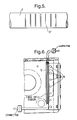
- Figure 6 shows an optical fibre ribbon cable 12 with connectors at each end for attachment to electro-optical light source, switch and detector circuits in the manner shown in Figure 3 positioned adjacent to a line of fasteners 36 in a typical aircraft structure.
- Figure 4 shows the effect of crack propagation across the fibre direction of the ribbon cable with connectors at either end in the manner of our invention and thus the damage to the fibres that will be detected by analysis.
- the fibres within the ribbon cable can be utilised to monitor point strain measurements by the inclusion of Bragg Gratings along the length of specific fibres.
- Figure 5 shows one such grating 37 which when subjected to strain within the ribbon cable 12 will deform and thus produce a change in the reflected light characteristic of that fibre 2 which will be recognised by the detection system 20 and 34 (see Figure 3) as changes in strain levels.
Landscapes
- Chemical & Material Sciences (AREA)
- Analytical Chemistry (AREA)
- Physics & Mathematics (AREA)
- General Physics & Mathematics (AREA)
- Length Measuring Devices By Optical Means (AREA)
- Light Guides In General And Applications Therefor (AREA)
- Investigating Materials By The Use Of Optical Means Adapted For Particular Applications (AREA)
Claims (2)
- Procédé de mesure de défauts structurels d'une structure, comprenant les étapes suivantes :a) la fixation de la structure à au moins un capteur de défauts structurels comprenant chacun plusieurs câbles longitudinaux (2) de fibres optiques montées avec un espacement prédéterminé en direction pratiquement parallèle à un ensemble coplanaire (12), un côté de l'ensemble (12) étant destiné à être fixé à une surface (6) d'une structure à éprouver,b) l'accouplement des deux extrémités de chacun des câbles à fibres optiques (2) à deux sources lumineuses séparées (18, 26) par l'intermédiaire de commutateurs optiques respectifs (16, 30),c) le contrôle des variations des paramètres de la lumière aux deux extrémités des câbles à fibres optiques (2), etd) la détermination (22) et l'affichage (24), d'après les variations contrôlées, de paramètres décrivant des discontinuités de la structure.
- Capteur de défauts structurels comprenant plusieurs câbles longitudinaux (2) de fibres optiques, montés sous forme d'un ensemble coplanaire pratiquement parallèle (12) avec un espacement prédéterminé, un premier côté de l'ensemble (12) étant destiné à être fixé à une surface (6) d'une structure à éprouver, caractérisé en ce que le capteur comprend en outre des connecteurs (10, 32) d'extrémité de ruban aux deux extrémités de l'ensemble (12) pour la connexion à deux sources lumineuses électro-optiques séparées (18, 26), à des commutateurs (16, 30) et à des circuits détecteurs (20, 34) dont les signaux de sortie peuvent être traités par un processeur (22) destiné à indiquer des paramètres décrivant des discontinuités sur un dispositif d'affichage (24).
Applications Claiming Priority (2)
| Application Number | Priority Date | Filing Date | Title |
|---|---|---|---|
| GB9317576 | 1993-08-24 | ||
| GB939317576A GB9317576D0 (en) | 1993-08-24 | 1993-08-24 | Fibre optic damage detection system |
Publications (2)
| Publication Number | Publication Date |
|---|---|
| EP0640824A1 EP0640824A1 (fr) | 1995-03-01 |
| EP0640824B1 true EP0640824B1 (fr) | 1998-10-21 |
Family
ID=10740946
Family Applications (1)
| Application Number | Title | Priority Date | Filing Date |
|---|---|---|---|
| EP94306190A Expired - Lifetime EP0640824B1 (fr) | 1993-08-24 | 1994-08-22 | Système de détection de défauts par fibre optique |
Country Status (5)
| Country | Link |
|---|---|
| US (1) | US5723857A (fr) |
| EP (1) | EP0640824B1 (fr) |
| JP (1) | JPH07174527A (fr) |
| DE (1) | DE69414056T2 (fr) |
| GB (1) | GB9317576D0 (fr) |
Families Citing this family (53)
| Publication number | Priority date | Publication date | Assignee | Title |
|---|---|---|---|---|
| SE503669C2 (sv) * | 1994-09-14 | 1996-07-29 | Cma Microdialysis Holding Ab | Förfarande för analys samt anordning för genomförande av förfarandet |
| NL9401493A (nl) * | 1994-09-15 | 1996-04-01 | Hollandse Signaalapparaten Bv | Inrichting voor het vaststellen van schade aan een schip. |
| GB9521957D0 (en) * | 1995-10-26 | 1996-01-03 | Limited | Strain gauge |
| GB9523240D0 (en) * | 1995-11-14 | 1996-01-17 | Secr Defence | Damage sensors |
| US5945665A (en) * | 1997-05-09 | 1999-08-31 | Cidra Corporation | Bolt, stud or fastener having an embedded fiber optic Bragg Grating sensor for sensing tensioning strain |
| US5973317A (en) * | 1997-05-09 | 1999-10-26 | Cidra Corporation | Washer having fiber optic Bragg Grating sensors for sensing a shoulder load between components in a drill string |
| US6492636B1 (en) * | 1997-08-19 | 2002-12-10 | The University Of Maryland | Large scale high speed multiplexed optical fiber sensor network |
| US6215927B1 (en) * | 1998-05-26 | 2001-04-10 | Minnesota Mining & Maufacturing Company | Sensing tapes for strain and/or temperature sensing |
| US6522797B1 (en) | 1998-09-01 | 2003-02-18 | Input/Output, Inc. | Seismic optical acoustic recursive sensor system |
| US6363192B1 (en) * | 1998-12-23 | 2002-03-26 | Corning Cable Systems Llc | Composite cable units |
| JP4493808B2 (ja) * | 2000-07-10 | 2010-06-30 | 株式会社アドバンテスト | 光特性測定装置、方法、記録媒体 |
| JP3415825B2 (ja) * | 2000-08-18 | 2003-06-09 | ショーボンド建設株式会社 | コンクリート構造物の損傷の進行を確認するための面状歪センサー及びコンクリート構造物の損傷の進行を確認する方法。 |
| KR100379746B1 (ko) * | 2000-12-16 | 2003-04-11 | 광주과학기술원 | 구조물 변형 측정 장치 및 구조물 변형 측정방법 |
| GB0031646D0 (en) * | 2000-12-22 | 2001-02-07 | European Community | Method and apparatus for crack and fracture detection utilizing bragg gratings |
| US7167009B2 (en) * | 2002-04-16 | 2007-01-23 | Mide Technology Corporation | Method and apparatus for determining electrical properties of structures |
| DE10238862B4 (de) * | 2002-08-24 | 2006-05-24 | Mtu Aero Engines Gmbh | Messtechnische Anordnung zur Prüfung von Werkstücken sowie Verfahren zur messtechnischen Instrumentierung von Werkstücken |
| US20040046109A1 (en) * | 2002-09-05 | 2004-03-11 | Chen Peter C. | Method and apparatus for high speed interrogation of fiber optic detector arrays |
| US7119325B2 (en) * | 2003-01-27 | 2006-10-10 | Bookham Technology Plc | System and method for monitoring environmental effects using optical sensors |
| AU2003902259A0 (en) * | 2003-05-13 | 2003-05-29 | Telezygology Inc. | Improved assembly system |
| US6917750B2 (en) * | 2003-05-29 | 2005-07-12 | 3M Innovative Properties Company | System and method for characterizing optical devices |
| JP4377642B2 (ja) * | 2003-09-26 | 2009-12-02 | 富士重工業株式会社 | 構造用複合材料の損傷探知システム |
| US7781725B2 (en) * | 2004-10-21 | 2010-08-24 | Mossman Guy E | Optical fiber based sensor system suitable for monitoring remote aqueous infiltration |
| US20050082467A1 (en) * | 2003-10-21 | 2005-04-21 | Guy Mossman | Optical fiber based sensor system suitable for monitoring remote aqueous infiltration |
| US20050236559A1 (en) * | 2004-03-12 | 2005-10-27 | Calvert Sean G | Fiber grating strain sensors for civil structures |
| BRPI0418715A (pt) * | 2004-03-24 | 2007-09-11 | Ten Cate Geosynthetics France | processo para localizar e medir as deformações de uma obra de engenharia civil |
| JP4588432B2 (ja) * | 2004-12-15 | 2010-12-01 | 富士重工業株式会社 | 損傷探知用モジュール化センサの製造方法 |
| DE102005012689B3 (de) * | 2005-03-18 | 2006-11-23 | Siemens Ag | Verfahren zum Herstellen eines Bandes |
| US20070003182A1 (en) * | 2005-06-29 | 2007-01-04 | Hunn David L | Fiber optic impact sensing system and method of using same |
| US7657134B2 (en) * | 2005-06-29 | 2010-02-02 | Lockheed Martin Corporation | Impact-sensing thermal insulation system and missile incorporating same |
| DE102005046934A1 (de) * | 2005-09-30 | 2007-02-22 | Siemens Ag | Verfahren zum Herstellen eines Bandes |
| JP4878013B2 (ja) * | 2007-08-27 | 2012-02-15 | 国立大学法人 東京大学 | 亀裂発生位置の検出方法 |
| GB0722319D0 (en) * | 2007-11-14 | 2007-12-27 | Rolls Royce Plc | Component monitoring arrangement |
| EP2260281B1 (fr) | 2008-03-31 | 2017-05-03 | Vestas Wind Systems A/S | Capteur de déformation à transmission optique pour éoliennes |
| US8515675B2 (en) * | 2008-04-02 | 2013-08-20 | Bakes Hughes Incorporated | Method for analyzing strain data |
| GB2461532A (en) | 2008-07-01 | 2010-01-06 | Vestas Wind Sys As | Sensor system and method for detecting deformation in a wind turbine component |
| GB2461566A (en) | 2008-07-03 | 2010-01-06 | Vestas Wind Sys As | Embedded fibre optic sensor for mounting on wind turbine components and method of producing the same. |
| GB2463696A (en) | 2008-09-22 | 2010-03-24 | Vestas Wind Sys As | Edge-wise bending insensitive strain sensor system |
| GB2466433B (en) | 2008-12-16 | 2011-05-25 | Vestas Wind Sys As | Turbulence sensor and blade condition sensor system |
| US20100161244A1 (en) * | 2008-12-18 | 2010-06-24 | Sikorsky Aircraft Corporation | Method and apparatus for monitoring structural health |
| KR100945149B1 (ko) * | 2008-12-19 | 2010-03-08 | 주식회사 금륜방재산업 | 초고층 건물의 방재 시스템 및 방법 |
| GB2472437A (en) | 2009-08-06 | 2011-02-09 | Vestas Wind Sys As | Wind turbine rotor blade control based on detecting turbulence |
| GB2477529A (en) | 2010-02-04 | 2011-08-10 | Vestas Wind Sys As | A wind turbine optical wind sensor for determining wind speed and direction |
| US8964172B1 (en) * | 2010-09-27 | 2015-02-24 | Rockwell Collins, Inc. | Means to detect damage in composite material panels |
| US8576392B2 (en) * | 2011-02-09 | 2013-11-05 | Siemens Energy, Inc. | Multiplexed optical fiber crack sensor |
| CN102841097B (zh) * | 2012-09-05 | 2015-01-14 | 同济大学 | 基于高精度复位技术的损伤阈值测量方法及测量装置 |
| DE102013108308A1 (de) * | 2013-08-01 | 2015-02-19 | Schott Ag | Verfahren und Vorrichtung zur Detektion in Bandrollen aus sprödhartem oder sprödbrechendem, zumindest teiltransparentem Material, sowie deren Verwendung |
| US9061425B2 (en) * | 2013-10-15 | 2015-06-23 | Avago Technologies General Ip (Singapore) Pte. Ltd. | Frame transfer device for an optical strain gauge structure |
| CN104215500B (zh) * | 2014-08-22 | 2016-08-24 | 奇瑞汽车股份有限公司 | 一种疲劳试验自动记数装置和自动记数方法 |
| EP3688433A4 (fr) * | 2017-09-27 | 2021-05-05 | Sikorsky Aircraft Corporation | Utilisation de capteurs de contrainte à fibre optique pour surveiller des dommages de fixation dans des structures |
| US10523317B2 (en) * | 2018-06-05 | 2019-12-31 | Sumitomo Electric Industries, Ltd. | Measurement system and measurement method |
| US12295890B2 (en) * | 2020-12-28 | 2025-05-13 | GE Precision Healthcare LLC | Infant care device including predictive failure side panels |
| GB2608145A (en) | 2021-06-23 | 2022-12-28 | Airbus Operations Ltd | Optical sensing system |
| DE112024000875T5 (de) * | 2023-02-16 | 2026-02-26 | Micron Technology, Inc. | Lötmaskenfehler faseroptischer sensor |
Family Cites Families (19)
| Publication number | Priority date | Publication date | Assignee | Title |
|---|---|---|---|---|
| US4629318A (en) * | 1981-03-26 | 1986-12-16 | Vfw Gmbh | Measuring device for determining cracks |
| DE3142392A1 (de) * | 1981-03-26 | 1983-05-11 | Vereinigte Flugtechnische Werke Gmbh, 2800 Bremen | Messanordnung zum feststellen von rissen |
| DE3131870A1 (de) * | 1981-08-12 | 1983-02-24 | Philips Kommunikations Industrie AG, 8500 Nürnberg | Mittels lichtwellenleiter auf bruch oder dehnung ueberwachbares bauteil |
| US4496215A (en) * | 1982-09-23 | 1985-01-29 | Rockwell International Corporation | Fiber optic cable |
| EP0116685A1 (fr) * | 1982-11-20 | 1984-08-29 | Messerschmitt-Bölkow-Blohm Gesellschaft mit beschränkter Haftung | Dispositif optique de détection de fissures |
| GB2136119A (en) * | 1983-03-08 | 1984-09-12 | Nmi Ltd | Crack Monitor |
| GB8322485D0 (en) * | 1983-08-20 | 1983-09-21 | Nmi Ltd | Crack monitor systems |
| US4692610A (en) * | 1986-01-30 | 1987-09-08 | Grumman Aerospace Corporation | Fiber optic aircraft load relief control system |
| US4733068A (en) * | 1986-04-07 | 1988-03-22 | Rockwell International Corporation | Crossed fiber optic tactile sensor |
| DE3629430A1 (de) * | 1986-08-29 | 1988-03-10 | Messerschmitt Boelkow Blohm | Messanordnung zum feststellen von rissen in strukturbauteilen von luftfahrzeugen |
| US5038618A (en) * | 1986-11-11 | 1991-08-13 | British Aerospace Public Limited Company | Measurement of distortion |
| US5013908A (en) * | 1988-11-28 | 1991-05-07 | Kaman Sciences Corporation | Break detection system using optical fibers having unique frequency modulated light |
| GB8828408D0 (en) * | 1988-12-06 | 1989-01-05 | British Telecomm | Loss detector |
| US4936649A (en) * | 1989-01-25 | 1990-06-26 | Lymer John D | Damage evaluation system and method using optical fibers |
| US4996419A (en) * | 1989-12-26 | 1991-02-26 | United Technologies Corporation | Distributed multiplexed optical fiber Bragg grating sensor arrangeement |
| US5182449A (en) * | 1990-02-06 | 1993-01-26 | The Boeing Corporation | System and method for structural monitoring using optical imaging of fiber sensors |
| US5142141A (en) * | 1990-09-19 | 1992-08-25 | The Boeing Company | Crack growth measurement network with primary and shunt optical fibers |
| JP2866186B2 (ja) * | 1990-11-05 | 1999-03-08 | 株式会社豊田中央研究所 | 電磁界強度測定装置 |
| US5399854A (en) * | 1994-03-08 | 1995-03-21 | United Technologies Corporation | Embedded optical sensor capable of strain and temperature measurement using a single diffraction grating |
-
1993
- 1993-08-24 GB GB939317576A patent/GB9317576D0/en active Pending
-
1994
- 1994-08-22 EP EP94306190A patent/EP0640824B1/fr not_active Expired - Lifetime
- 1994-08-22 DE DE69414056T patent/DE69414056T2/de not_active Expired - Lifetime
- 1994-08-23 JP JP6198807A patent/JPH07174527A/ja active Pending
-
1996
- 1996-05-08 US US08/646,868 patent/US5723857A/en not_active Expired - Lifetime
Also Published As
| Publication number | Publication date |
|---|---|
| DE69414056T2 (de) | 1999-03-18 |
| US5723857A (en) | 1998-03-03 |
| GB9317576D0 (en) | 1993-10-06 |
| JPH07174527A (ja) | 1995-07-14 |
| EP0640824A1 (fr) | 1995-03-01 |
| DE69414056D1 (de) | 1998-11-26 |
Similar Documents
| Publication | Publication Date | Title |
|---|---|---|
| US5723857A (en) | Method and apparatus for detecting cracks and strains on structures using optical fibers and Bragg gratings | |
| US5118931A (en) | Fiber optic microbending sensor arrays including microbend sensors sensitive over different bands of wavelengths of light | |
| US5321257A (en) | Fiber optic bending and positioning sensor including a light emission surface formed on a portion of a light guide | |
| US4733068A (en) | Crossed fiber optic tactile sensor | |
| US6621947B1 (en) | Apparatus and method for monitoring a structure using a counter-propagating signal method for locating events | |
| Lee et al. | Monitoring of fatigue damage of composite structures by using embedded intensity-based optical fiber sensors | |
| CA2584376C (fr) | Capteur fibre optique polarimetrique integrable et procede de surveillance de structures | |
| US4947693A (en) | Discrete strain sensor | |
| Quach et al. | Structural anomaly detection using fiber optic sensors and inverse finite element method | |
| US4900920A (en) | Device for and method of measuring minute elongations by means of light wave conductor sensors | |
| WO1993025866A1 (fr) | Pieces de detection utilisant un detecteur a guide d'ondes incorpore | |
| MacPherson et al. | Tunnel monitoring using multicore fibre displacement sensor | |
| EP0573778A1 (fr) | Capteur à fibres optiques pour connexions | |
| CN101228421A (zh) | 光学应变片 | |
| WO2019139387A1 (fr) | Appareil et procédé de détection d'une détérioration de matériau composite due à un impact au moyen de fibres optiques distribuées | |
| US5638165A (en) | Crack detection system | |
| JP6301963B2 (ja) | 歪みセンサ及び歪みセンサの設置方法 | |
| Measures | Smart structures with nerves of glass | |
| Green et al. | Infrastructure development for incorporating fibre-optic sensors in composite materials | |
| JP3544861B2 (ja) | 計測対象区間識別方法 | |
| Duncan et al. | Distributed sensing technique for test article damage detection and monitoring | |
| Seaver et al. | Underwater blast loading of a composite twisted rudder with FBGs | |
| Burnett et al. | Optical Fibre‐based Vectoral Shape Sensor | |
| Wei et al. | Application issues using fibre Bragg gratings as strain sensors in fibre composites | |
| CN217819125U (zh) | 一种光纤应力及震动检测装置 |
Legal Events
| Date | Code | Title | Description |
|---|---|---|---|
| PUAI | Public reference made under article 153(3) epc to a published international application that has entered the european phase |
Free format text: ORIGINAL CODE: 0009012 |
|
| AK | Designated contracting states |
Kind code of ref document: A1 Designated state(s): DE FR GB IT SE |
|
| 17P | Request for examination filed |
Effective date: 19950831 |
|
| 17Q | First examination report despatched |
Effective date: 19970320 |
|
| GRAG | Despatch of communication of intention to grant |
Free format text: ORIGINAL CODE: EPIDOS AGRA |
|
| GRAG | Despatch of communication of intention to grant |
Free format text: ORIGINAL CODE: EPIDOS AGRA |
|
| GRAH | Despatch of communication of intention to grant a patent |
Free format text: ORIGINAL CODE: EPIDOS IGRA |
|
| GRAH | Despatch of communication of intention to grant a patent |
Free format text: ORIGINAL CODE: EPIDOS IGRA |
|
| GRAA | (expected) grant |
Free format text: ORIGINAL CODE: 0009210 |
|
| AK | Designated contracting states |
Kind code of ref document: B1 Designated state(s): DE FR GB IT SE |
|
| REF | Corresponds to: |
Ref document number: 69414056 Country of ref document: DE Date of ref document: 19981126 |
|
| ET | Fr: translation filed | ||
| PLBE | No opposition filed within time limit |
Free format text: ORIGINAL CODE: 0009261 |
|
| STAA | Information on the status of an ep patent application or granted ep patent |
Free format text: STATUS: NO OPPOSITION FILED WITHIN TIME LIMIT |
|
| 26N | No opposition filed | ||
| REG | Reference to a national code |
Ref country code: FR Ref legal event code: CD |
|
| REG | Reference to a national code |
Ref country code: GB Ref legal event code: IF02 |
|
| PGFP | Annual fee paid to national office [announced via postgrant information from national office to epo] |
Ref country code: SE Payment date: 20120821 Year of fee payment: 19 Ref country code: GB Payment date: 20120821 Year of fee payment: 19 |
|
| PGFP | Annual fee paid to national office [announced via postgrant information from national office to epo] |
Ref country code: IT Payment date: 20120823 Year of fee payment: 19 Ref country code: DE Payment date: 20120822 Year of fee payment: 19 Ref country code: FR Payment date: 20120906 Year of fee payment: 19 |
|
| REG | Reference to a national code |
Ref country code: SE Ref legal event code: EUG |
|
| GBPC | Gb: european patent ceased through non-payment of renewal fee |
Effective date: 20130822 |
|
| PG25 | Lapsed in a contracting state [announced via postgrant information from national office to epo] |
Ref country code: SE Free format text: LAPSE BECAUSE OF NON-PAYMENT OF DUE FEES Effective date: 20130823 Ref country code: DE Free format text: LAPSE BECAUSE OF NON-PAYMENT OF DUE FEES Effective date: 20140301 |
|
| REG | Reference to a national code |
Ref country code: DE Ref legal event code: R119 Ref document number: 69414056 Country of ref document: DE Effective date: 20140301 |
|
| REG | Reference to a national code |
Ref country code: FR Ref legal event code: ST Effective date: 20140430 |
|
| PG25 | Lapsed in a contracting state [announced via postgrant information from national office to epo] |
Ref country code: IT Free format text: LAPSE BECAUSE OF NON-PAYMENT OF DUE FEES Effective date: 20130822 |
|
| PG25 | Lapsed in a contracting state [announced via postgrant information from national office to epo] |
Ref country code: GB Free format text: LAPSE BECAUSE OF NON-PAYMENT OF DUE FEES Effective date: 20130822 |
|
| PG25 | Lapsed in a contracting state [announced via postgrant information from national office to epo] |
Ref country code: FR Free format text: LAPSE BECAUSE OF NON-PAYMENT OF DUE FEES Effective date: 20130902 |