EP0640848B1 - Geraet zum Messen von Gammaspektren in verrohrtem Bohrloch - Google Patents
Geraet zum Messen von Gammaspektren in verrohrtem Bohrloch Download PDFInfo
- Publication number
- EP0640848B1 EP0640848B1 EP19930306819 EP93306819A EP0640848B1 EP 0640848 B1 EP0640848 B1 EP 0640848B1 EP 19930306819 EP19930306819 EP 19930306819 EP 93306819 A EP93306819 A EP 93306819A EP 0640848 B1 EP0640848 B1 EP 0640848B1
- Authority
- EP
- European Patent Office
- Prior art keywords
- gamma ray
- energy
- neutron
- gamma
- spectra
- Prior art date
- Legal status (The legal status is an assumption and is not a legal conclusion. Google has not performed a legal analysis and makes no representation as to the accuracy of the status listed.)
- Expired - Lifetime
Links
- 238000001228 spectrum Methods 0.000 title claims description 26
- XEEYBQQBJWHFJM-UHFFFAOYSA-N Iron Chemical compound [Fe] XEEYBQQBJWHFJM-UHFFFAOYSA-N 0.000 claims description 28
- 230000005251 gamma ray Effects 0.000 claims description 27
- 238000000084 gamma-ray spectrum Methods 0.000 claims description 22
- 229910052742 iron Inorganic materials 0.000 claims description 12
- 230000015572 biosynthetic process Effects 0.000 claims description 10
- 238000005755 formation reaction Methods 0.000 claims description 10
- 229910052799 carbon Inorganic materials 0.000 claims description 8
- 229910052760 oxygen Inorganic materials 0.000 claims description 8
- OKTJSMMVPCPJKN-UHFFFAOYSA-N Carbon Chemical compound [C] OKTJSMMVPCPJKN-UHFFFAOYSA-N 0.000 claims description 7
- QVGXLLKOCUKJST-UHFFFAOYSA-N atomic oxygen Chemical compound [O] QVGXLLKOCUKJST-UHFFFAOYSA-N 0.000 claims description 7
- 239000001301 oxygen Substances 0.000 claims description 7
- 239000011575 calcium Substances 0.000 claims description 6
- 229910052791 calcium Inorganic materials 0.000 claims description 6
- 230000005855 radiation Effects 0.000 claims description 6
- 229910052710 silicon Inorganic materials 0.000 claims description 6
- OYPRJOBELJOOCE-UHFFFAOYSA-N Calcium Chemical compound [Ca] OYPRJOBELJOOCE-UHFFFAOYSA-N 0.000 claims description 5
- 239000010703 silicon Substances 0.000 claims description 5
- XUIMIQQOPSSXEZ-UHFFFAOYSA-N Silicon Chemical compound [Si] XUIMIQQOPSSXEZ-UHFFFAOYSA-N 0.000 claims description 4
- 229910052797 bismuth Inorganic materials 0.000 claims description 4
- JCXGWMGPZLAOME-UHFFFAOYSA-N bismuth atom Chemical compound [Bi] JCXGWMGPZLAOME-UHFFFAOYSA-N 0.000 claims description 4
- 239000012530 fluid Substances 0.000 claims description 4
- 239000000463 material Substances 0.000 claims description 3
- ZAMOUSCENKQFHK-UHFFFAOYSA-N Chlorine atom Chemical compound [Cl] ZAMOUSCENKQFHK-UHFFFAOYSA-N 0.000 claims description 2
- 239000004568 cement Substances 0.000 claims description 2
- 239000000460 chlorine Substances 0.000 claims description 2
- 229910052801 chlorine Inorganic materials 0.000 claims description 2
- 229910052739 hydrogen Inorganic materials 0.000 claims description 2
- 239000001257 hydrogen Substances 0.000 claims description 2
- 230000000087 stabilizing effect Effects 0.000 claims description 2
- ZLMJMSJWJFRBEC-UHFFFAOYSA-N Potassium Chemical compound [K] ZLMJMSJWJFRBEC-UHFFFAOYSA-N 0.000 claims 1
- NINIDFKCEFEMDL-UHFFFAOYSA-N Sulfur Chemical compound [S] NINIDFKCEFEMDL-UHFFFAOYSA-N 0.000 claims 1
- RTAQQCXQSZGOHL-UHFFFAOYSA-N Titanium Chemical compound [Ti] RTAQQCXQSZGOHL-UHFFFAOYSA-N 0.000 claims 1
- 125000004435 hydrogen atom Chemical class [H]* 0.000 claims 1
- 239000011591 potassium Substances 0.000 claims 1
- 229910052700 potassium Inorganic materials 0.000 claims 1
- 229910052717 sulfur Inorganic materials 0.000 claims 1
- 239000011593 sulfur Substances 0.000 claims 1
- 239000010936 titanium Substances 0.000 claims 1
- 229910052719 titanium Inorganic materials 0.000 claims 1
- 238000000034 method Methods 0.000 description 12
- 230000006641 stabilisation Effects 0.000 description 10
- 238000011105 stabilization Methods 0.000 description 10
- 238000010586 diagram Methods 0.000 description 7
- 238000005259 measurement Methods 0.000 description 6
- FVAUCKIRQBBSSJ-UHFFFAOYSA-M sodium iodide Chemical compound [Na+].[I-] FVAUCKIRQBBSSJ-UHFFFAOYSA-M 0.000 description 6
- 230000003595 spectral effect Effects 0.000 description 5
- 238000001730 gamma-ray spectroscopy Methods 0.000 description 4
- 238000001514 detection method Methods 0.000 description 3
- 230000006870 function Effects 0.000 description 3
- 239000003381 stabilizer Substances 0.000 description 3
- 230000005283 ground state Effects 0.000 description 2
- 239000000203 mixture Substances 0.000 description 2
- 239000003921 oil Substances 0.000 description 2
- 235000009518 sodium iodide Nutrition 0.000 description 2
- 238000010183 spectrum analysis Methods 0.000 description 2
- XLYOFNOQVPJJNP-UHFFFAOYSA-N water Substances O XLYOFNOQVPJJNP-UHFFFAOYSA-N 0.000 description 2
- UFHFLCQGNIYNRP-UHFFFAOYSA-N Hydrogen Chemical compound [H][H] UFHFLCQGNIYNRP-UHFFFAOYSA-N 0.000 description 1
- 229910000831 Steel Inorganic materials 0.000 description 1
- 230000003321 amplification Effects 0.000 description 1
- 238000004458 analytical method Methods 0.000 description 1
- 230000001143 conditioned effect Effects 0.000 description 1
- 239000004020 conductor Substances 0.000 description 1
- 230000003247 decreasing effect Effects 0.000 description 1
- 230000000694 effects Effects 0.000 description 1
- 230000004907 flux Effects 0.000 description 1
- 230000002401 inhibitory effect Effects 0.000 description 1
- 230000000155 isotopic effect Effects 0.000 description 1
- 239000011159 matrix material Substances 0.000 description 1
- CSJDCSCTVDEHRN-UHFFFAOYSA-N methane;molecular oxygen Chemical compound C.O=O CSJDCSCTVDEHRN-UHFFFAOYSA-N 0.000 description 1
- 238000001956 neutron scattering Methods 0.000 description 1
- 238000003199 nucleic acid amplification method Methods 0.000 description 1
- 150000003839 salts Chemical class 0.000 description 1
- 239000010959 steel Substances 0.000 description 1
Images


Classifications
-
- G—PHYSICS
- G01—MEASURING; TESTING
- G01V—GEOPHYSICS; GRAVITATIONAL MEASUREMENTS; DETECTING MASSES OR OBJECTS; TAGS
- G01V5/00—Prospecting or detecting by the use of ionising radiation, e.g. of natural or induced radioactivity
- G01V5/04—Prospecting or detecting by the use of ionising radiation, e.g. of natural or induced radioactivity specially adapted for well-logging
- G01V5/08—Prospecting or detecting by the use of ionising radiation, e.g. of natural or induced radioactivity specially adapted for well-logging using primary nuclear radiation sources or X-rays
- G01V5/10—Prospecting or detecting by the use of ionising radiation, e.g. of natural or induced radioactivity specially adapted for well-logging using primary nuclear radiation sources or X-rays using neutron sources
- G01V5/101—Prospecting or detecting by the use of ionising radiation, e.g. of natural or induced radioactivity specially adapted for well-logging using primary nuclear radiation sources or X-rays using neutron sources and detecting the secondary Y-rays produced in the surrounding layers of the bore hole
Definitions
- This invention relates to an apparatus for measuring gamma ray spectra in cased borehole.
- BGO bismuth germanate
- the merit of the high density scintillator relative to conventional sodium iodide detectors is that it provides substantially better detection efficiency. That is, a larger fraction of the total gamma ray flux is in the full energy or first escape peak. Less gamma ray energy is disposed in the structureless Compton scattered low energy tail, in the more dense bismuth germanate detectors relative to sodium iodide.
- US-A-4766543 there is disclosed a generalized computer-based system and method for acquisition of nuclear well logging data, including downhole generation of energy and time spectral information.
- a downhole instrument traverses a borehole introducing high energy neutrons into the formation at prescribed depths. Resultant gamma rays are detected and converted into pulses which are amplified and conditioned.
- a downhole multi-parameter analyzer stores pulse height and arrival time for each detected gamma ray whereby time and energy spectra are formed.
- Spectra include, alone or in combination, time spectra of the neutron source, inelastic and capture energy spectra. From the source time spectra, peaks are detected and capture and inelastic gates referenced thereto. Also thermal neutron decay between source bursts is derived. From the energy spectra peaks including hydrogen or iron are detected and used for calibration and automatic gain control of the gamma ray detector.
- High speed buffer means and direct memory access enables access to memory by both the multi-parameter analyzer and CPU so as to avoid inhibiting data acquisition during processing of the acquired spectra by the CPU.
- Parameters including pulse discrimination level, detector gain, and gate positioning affecting the spectra generated downhole, which may simultaneously include inelastic, capture, and time distribution spectra, are variable in the analyzer by means of CPU control functions.
- US-A-3767921 there is disclosed a method and apparatus for gamma ray spectroscopy well logging systems including a closed loop linearity control feature.
- a borehole tool provides gamma ray pulse data.
- the gamma ray counts in at least two portions of the gamma ray energy spectrum chosen so that their ratio remains relatively constant under usual borehole conditions are monitored.
- An error signal is developed if the ratio of gamma ray counts in the monitored portions of the energy spectrum deviate significantly from the constant ratio.
- the error signal is used to control the power supply voltage for the borehole tool and/or the surface amplification of the gamma ray pulse signals to preserve system linearity.
- apparatus for measuring gamma ray spectra in cased well boreholes which apparatus comprises:
- the induced gamma ray spectrometry tool of the present invention uses a monoenergetic, preferably 14 MeV, source to irradiate earth formations in the vicinity of the borehole with 14 MeV neutrons.
- Time gates are provided to detect both capture gamma ray spectra and an inelastic scattering gamma ray spectrum.
- a bismuth germanate (BGO) detector is preferably used in the system of the present invention.
- Output pulses from the photomultiplier tube which is optically coupled to the BGO detector are supplied to a pulse height analyzer, having 256 channel of energy resolution.
- a portion of the measured capture gamma ray spectrum itself, employing the iron edge, is used to gain stabilize pulse height analyzer circuitry thereby making it extremely stable.
- the downhole measured pulse height spectra are accumulated in a downhole memory which is part of the pulse height analyzer and are telemetered to the surface via a digital telemetry system at regular intervals.
- a surface computer then is programmed to analyze the spectra and to record various quantities of interest, such as the carbon/oxygen ratio; the silicon to calcium ratio; and other parameters of interest in neutron induced gamma ray spectroscopy logging.
- a well logging system in accordance with concepts of the present invention is illustrated in a very highly schematic manner in a cased well borehole.
- a well borehole 10 lined with a steel casing 30 and filled with a borehole fluid 11 penetrates earth formations 17, 18, 19 and 20 .
- the well logging cable 12 passes over a sheave wheel 13 which maybe electrically or mechanically coupled, as indicated by a dotted line 14, to a spectral analysis computer 15 and a data recorder 16 .
- the spectral analysis computer 15 may comprise, for example, any suitably programmed general purpose computer capable of receiving signals from the downhole equipment.
- the recorder 16 may comprise a strip chart recorder, as indicated having a record medium 17 , or may comprise a digital tape or a disk file memory as desired.
- the downhole sonde 21 comprises a power supply portion 22 , a timing circuit portion 23 , a telemetry portion 24 , a gain stabilizer portion 25 , a pulse height analyzer portion 26 , a detector portion 27 , a source portion 28 , and a high voltage power supply portion 29.
- the power supply portion 22 takes electrical power from one or more of the conductors of logging cable 12 and converts it to appropriate voltage and current levels for supplying internal circuits of the downhole sonde 21 with electrical power as required.
- the timing circuits as will be discussed in more detail subsequently in conjunction, with Figure 2, provide timing pulses for opening and closing various data gates and thereby operating various detection schemes according to the concepts of the invention.
- the telemetry circuitry 24 is a conventional digital telemetry system capable of communicating to and from the surface supplied equipment at a rate of 50 kilobits/sec.
- the gain stabilizer circuit 25 which will be described in more detail subsequently, operates in conjunction with the pulse height analyzer 26.
- the analyzer 26 receives signals from the detector portion of the tool 27.
- the detector signals are representative of gamma rays impinging upon the detector and which have been induced by a neutron bombardment from a neutron source 28 which is supplied for its operation by approximately 100 kilovolt high voltage power supply 29 or from a background gamma ray source.
- Figure 2 comprising a fast timing subycycle shown as Figure 2a and a slower timing subcycle shown as Figure 2b, illustrates the timing applied to both the neutron source 28 and the detector circuits 26,27 in the present invention.
- Figure 2b a timing cycle of 5 milliseconds in duration and repeated 50 times/sec. is illustrated.
- the neutron source 28 is turned on for a very short 14 MEV neutron pulse having a time duration of approximately 15 microseconds at the beginning of this 5 millisecond duration sub-cycle.
- a plurality of time gates are opened to measure the thermal neutron population die-away as a function of time. Up to six, eight or even more gates maybe used as desired according to known techniques such as that of U.S. Patent 4,424,444. Using this technique the borehole and formation thermal neutron capture cross-sections are measured. Thus the die-away of thermal neutrons produced by the moderation of the fast neutrons emitted by the neutron source 28 are detected for the first two milliseconds of this 5 millisecond subcycle.
- the detector 27 is used to detect background gamma radiation due to naturally occurring gamma rays in the earth formations surrounding the well bore. All measurements may thus be corrected for background based on this background measurement by subtraction of the appropriately scaled count rate.
- the neutron source is pulsed on for fifteen microsecond duration pulses (indicated as NB in the timing diagram).
- NB microsecond duration pulses
- an inelastic scattering gamma ray time gate is opened allowing pulses from the detector 27 occurring during the neutron burst to be gated to the pulse height analyzer circuitry 26.
- the detector 27 is gated off for approximately 5 microseconds. This allow thermalization of the fast neutrons.
- a first capture gamma ray time gate having a duration of thirty-five from 20 to 55 microseconds is opened.
- a second capture gamma ray time gate having a duration of thirty-five microseconds (from 55 to 90 microseconds) is opened thereafter.
- These gates are labelled respectively CG1 and CG2 in Figure 2a.
- the entire short or fast pulse cycle is then repeated beginning at the time labelled 100 microseconds of Figure 2a and the neutron source and detector timing are repeated as previously described for the next 100 microseconds.
- the entire sequence which is illustrated in Figure 2a is repeated for a period of 1500 microseconds.
- the short or fast pulse subintervals of 100 microseconds duration are time interlocked with the longer 5 millisecond intervals illustrated in Figure 2B. Timing pulses suitable for this purpose are produced in Timing Circuit section 23 of Figure 1.
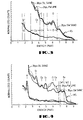
- an inelastic gamma ray energy spectrum which comprises gamma ray pulses detected during the gates labelled IG (inelastic gamma rays) in Figure 2a and supplied to the pulse height analyzer 26 during this time when the neutron bursts are on is shown schematically. It will be observed that in the inelastic gamma ray spectrum that inelastic scattering peaks attributable to carbon, oxygen, silicon and calcium appear in the inelastic gamma ray spectrum.
- the inelastic spectrum of course is caused by a fast neutron scattering from the nucleus of an element in the vicinity of the borehole and exciting these nuclei to higher energy levels thereby losing some of fine energy of the scattered neutrons (ie. scattering with energy loss).
- the excited nuclei returning to the ground state emit gamma rays characteristic of each of the nuclear species.
- Energy windows labelled C, O, Ca, Si are shown in the spectrum of Figure 3 for the carbon, oxygen, silicon and calcium inelastic scattering energy peaks.
- a capture gamma ray spectrum is shown schematically.
- the capture gamma ray spectrum is taken in gates labelled CG 1 and CG2 in Figure 2a. This spectrum is attributable to the emission of gamma rays by the decay to the ground state of nuclei which have been excited by the capture of thermalized neutrons.
- the waiting period of 5 microseconds between the end of the neutron burst to the beginning of the capture gamma ray gates illustrated in Figure 2a allows for thermalization of the fast 14 MeV neutrons emitted by the source 28 to achieve a thermal neutron population.
- the iron peak (labelled Fe in Figure 4) occurs at an energy of 7.65 MeV.
- Energy windows labelled W1 and W2 are positioned to straddle the Fe peak and are used for system gain control purposes.
- the iron peak will of course always be present in a cased well borehole in which the pulsed spectral gamma ray tool according to the concepts of the present invention is deployed.
- the iron edge is always a prominent feature in cased well borehole spectrum, because the casing and the tool housing both contain iron.
- the iron peak is located at 7.65 MeV and is discernable, but not very prominent, in the capture gamma ray spectrum of Figure 4. This peak becomes less prominent if chlorine infested or salt water is present in the earth formations surrounding the borehole.
- all of the capture gamma ray spectra show a precipitous drop at energies just above the iron 7.65 MeV line.
- two equal width adjacent windows labelled W1 and W2 spanning this edge are indicated in Figure 4. Equality of width of these energy windows is not a critical requirement but is only made for convenience.
- a spectral procedure for gain stabilization is based upon the count rates in the energy windows labelled W1 and W2.
- This procedure which is implemented in a microprocessor program in gain stabilizer 25 adjusts the photomultiplier high voltage (contained in detector 27) to maintain the ratio of counts in the energy window labelled W1 to that in energy window labelled W2 equal to the integer two. Again, this value of 2.0 is not particularly necessary as any value in the range from two to three would probably work just as well. It is merely convenient to use.
- the gain of the photomultiplier portion of detector 27 is increased whenever the ratio becomes greater than 2.0 and the gain of the photomultiplier is decreased whenever the ratio becomes less than 2.0. This places the juncture of the two windows near the upper count rate portion of the iron (Fe) edge.
- a start up procedure is required to assume selection of the correct gain value. This is accomplished by raising the photomultiplier gain until the count rate in the upper window W2 exceeds a predetermined minimum value prior to beginning the gain stabilization process as previously described.
Landscapes
- Physics & Mathematics (AREA)
- High Energy & Nuclear Physics (AREA)
- Life Sciences & Earth Sciences (AREA)
- General Life Sciences & Earth Sciences (AREA)
- General Physics & Mathematics (AREA)
- Geophysics (AREA)
- Geophysics And Detection Of Objects (AREA)
- Measurement Of Radiation (AREA)
Claims (10)
- Gerät zum Messen von Gammaspektren in verrohrtem Bohrloch, bestehend aus:a) einer elektronischen Quelle (28) monogenetischer schneller Neutronen zur Ausstrahlung in Pulsform, die Bohrlochflüssigkeit (11), die Verrohrung (30) und deren zementösen Mantel durchdringen und in die Erdformationen im Bohrlochbereich eindringen, wo sie durch thermische Energie modifiziert und durch die Atomkerne der in und um das Bohrloch befindlichen Elemente aufgefangen werden;b) einem hochdichten Scintillationszähler (27), der optisch mit einem Photomultiplikator verbunden ist und der zum Erkennen von Gammastrahlung ausgeführt ist, die durch die erwähnten Neutronen induziert wird und Stromausgangssignale erzeugt, deren Höhe die Gammaenergie darstellt, die auf den hochdichten Scintillator auftrifft;c) einer Auswertungsvorrichtung für Pulshöhen (26), die mit dem Ausgang des erwähnten Scintillationszählers und dem Photomultiplikator verbunden ist und dem Trennen des Gammaenergiespektrums der auftreffenden Gammastrahlen in Energiekomponenten und dem Zählen der erwähnten Energiekomponenten als Funktion der Energie dient;d) einer Zeitgebervorrichtung (23) zum Erzeugen von Zeitgattern, mit denen schnelle durch Neutronen induzierte Gammastrahlen, thermische Neutronen-Einfang-Gammastrahlen und Hintergrund-Gammastrahlen vor ihrer Präsentation am erwähnten Impulshöhenanalysator separiert werden; unde) einer Verstärkungssteuerung (25), die den Eisenrand des thermischen Neutronen-Einfang-Gammaspektrums zur Verstärkungsstabilisierung des erwähnten Photomultiplikatorausgangs benutzt, um auf diese Weise den Verstärkungswert zu etablieren, der auf alle gemessenen unelastischen Einfang- und Hintergrundspektren angesetzt wird.
- Ein Gerät nach Anspruch 1, inklusive einer Vorrichtung zum Erzeugen von Gammastrahlungs-Energiespektren der durch unelastische Streuung induzierten Gammastrahlung während des Pulsierens schneller Neutronen.
- Ein Gerät nach Anspruch 2, bei dem die erwähnte Erzeugungsvorrichtung so ausgeführt ist, daß die unelastischen Gammaspektren in Energiekomponenten aufgeteilt werden und die unelastische Gammastrahlung dargestellt wird, die durch Kohle, Sauerstoff, Silikon und Kalzium erzeugt wird.
- Ein Gerät nach Anspruch 3, bei dem die thermischen Neutronen-Einfang-Gammaspektren der durch den Einfang erwärmter schneller Neutronen induzierten Gammastrahlung durch das stille Intervall zwischen den erwähnten Neutronenimpulsen festgestellt werden.
- Ein Gerät nach Anspruch 4, bei dem die erwähnten thermischen Neutronen-Einfang-Gammaspektren in Energiekomponenten unterteilt werden, die Einfang-Gammastrahlen aus Wasserstoff, Silikon, Kalzium, Chlor, Potassium, Schwefel, Titan und Eisen darstellen.
- Ein Gerät nach Anspruch 5, bei dem die erwähnte Verstärkungssteuerung (25) aus folgendem besteht: einem zum Regeln der Verstärkung des erwähnten Photomultiplikators programmierten Mikroprozessor, wobei die Verstärkung auf einem Verhältnis der Zählraten in zwei Energiefenstern beruht, die die 7,65 MEV Eisen (Fe)-Spitze überspannen.
- Ein Gerät nach Anspruch 6, bei dem der erwähnte Mikroprozessor zum Beibehalten des erwähnten Zählratenverhältnisses in den zwei Energiefenstern programmiert ist, die als festgelegte Konstante die 7,65 MEV Eisenspitze überspannen.
- Ein Gerät nach einem der Ansprüche 1 bis 7, weiter bestehend aus:f) einer Vorrichtung zum Erzeugen von Zeitgattern in der stillen Zeit zwischen den Neutronenstößen in einer Reihenfolge von mindestens vier solcher Gatter, um eine Folge von Zählungsraten zu erzeugen, die das Absterben der Besetzung der thermischen Neutronen, die von den schnellen Neutronenimpulsen erzeugt wurden, darstellen, wobei das erwähnte Gerät vorzugsweise folgendes beinhaltet;g) eine Vorrichtung zum Erzeugen von Zeitgattern in der stillen Zeit zwischen Neutronenstößen und Trennen aus der erwähnten Folge von wenigstens vier solcher Gatter, um eine Zählrate zu erzeugen, die die Hintergrund-Gammastrahlungszählrate im Bohrloch darstellt.
- Ein Gerät nach Anspruch 8, bei dem die unelastischen Gammaspektren, die Einfang-Gammaspektren und die Gatterzählrate der thermischen Neutronenabsterbezeit durch die in Schritt (g) gemessenen Zählraten bezüglich des Hintergrunds korrigiert werden.
- Ein Gerät nach einem der Ansprüche 1 bis 9, bei dem der Scintillationszähler einen Wismut-Germanatdetektor oder einen anderen Detektor enthält, der nicht aus hochdichtem Scintillationsstoff besteht.
Priority Applications (2)
| Application Number | Priority Date | Filing Date | Title |
|---|---|---|---|
| EP19930306819 EP0640848B1 (de) | 1993-08-27 | 1993-08-27 | Geraet zum Messen von Gammaspektren in verrohrtem Bohrloch |
| DE1993619242 DE69319242T2 (de) | 1993-08-27 | 1993-08-27 | Geraet zum Messen von Gammaspektren in verrohrtem Bohrloch |
Applications Claiming Priority (1)
| Application Number | Priority Date | Filing Date | Title |
|---|---|---|---|
| EP19930306819 EP0640848B1 (de) | 1993-08-27 | 1993-08-27 | Geraet zum Messen von Gammaspektren in verrohrtem Bohrloch |
Publications (2)
| Publication Number | Publication Date |
|---|---|
| EP0640848A1 EP0640848A1 (de) | 1995-03-01 |
| EP0640848B1 true EP0640848B1 (de) | 1998-06-17 |
Family
ID=8214522
Family Applications (1)
| Application Number | Title | Priority Date | Filing Date |
|---|---|---|---|
| EP19930306819 Expired - Lifetime EP0640848B1 (de) | 1993-08-27 | 1993-08-27 | Geraet zum Messen von Gammaspektren in verrohrtem Bohrloch |
Country Status (2)
| Country | Link |
|---|---|
| EP (1) | EP0640848B1 (de) |
| DE (1) | DE69319242T2 (de) |
Cited By (5)
| Publication number | Priority date | Publication date | Assignee | Title |
|---|---|---|---|---|
| US6247803B1 (en) | 1983-10-13 | 2001-06-19 | Seiko Epson Corporation | Ink jet recording apparatus and method for replenishing ink in the tank cartridge |
| WO2009120817A3 (en) * | 2008-03-26 | 2010-01-14 | Baker Hughes Incorporated | Inelastic background correction for a pulsed-neutron instrument |
| WO2013078263A1 (en) * | 2011-11-24 | 2013-05-30 | Schlumberger Canada Limited | Method and apparatus for gain regulation in a gamma detector |
| US8536517B2 (en) | 2008-11-10 | 2013-09-17 | Schlumberger Technology Corporation | Scintillator based radiation detection |
| US8546749B2 (en) | 2008-11-10 | 2013-10-01 | Schlumberger Technology Corporation | Intrinsic radioactivity in a scintillator as count rate reference |
Families Citing this family (7)
| Publication number | Priority date | Publication date | Assignee | Title |
|---|---|---|---|---|
| EP1579202B1 (de) | 2002-12-10 | 2007-04-18 | Commonwealth Scientific And Industrial Research Organisation | Radiographisches gerät |
| US7081616B2 (en) * | 2003-12-12 | 2006-07-25 | Schlumberger Technology Corporation | Downhole gamma-ray detection |
| WO2011006038A2 (en) * | 2009-07-10 | 2011-01-13 | Services Petroliers Schlumberger | Scintillator based radiation detection |
| MX339479B (es) * | 2012-04-19 | 2016-05-27 | Halliburton Energy Services Inc | Sistema y metodo para determinar un valor indicativo de indice de hidrogeno. |
| WO2013158428A1 (en) | 2012-04-19 | 2013-10-24 | Halliburton Energy Services, Inc. | System and method of determining a value indicative of hydrogen index |
| CN104704391B (zh) | 2012-10-24 | 2018-05-25 | 哈利伯顿能源服务公司 | 使用两点来稳定频谱 |
| WO2016053350A1 (en) * | 2014-10-03 | 2016-04-07 | Halliburton Energy Services, Inc. | Gain stabilization of a natural gamma ray tool |
Family Cites Families (8)
| Publication number | Priority date | Publication date | Assignee | Title |
|---|---|---|---|---|
| US3213279A (en) * | 1961-06-07 | 1965-10-19 | Socony Mobil Oil Co Inc | Calibration of radioactive well logging system |
| US3752984A (en) * | 1971-12-02 | 1973-08-14 | Texaco Inc | Methods and system for detecting subsurface minerals |
| US3767921A (en) * | 1972-03-31 | 1973-10-23 | Texaco Inc | Well logging system with linearity control |
| US4020342A (en) * | 1975-12-22 | 1977-04-26 | Texaco Inc. | Earth formation salinity by comparison of inelastic and capture gamma ray spectra |
| US4424444A (en) * | 1980-08-28 | 1984-01-03 | Halliburton Company | Method for simultaneous measurement of borehole and formation neutron lifetimes |
| US4596927A (en) * | 1983-02-24 | 1986-06-24 | Dresser Industries, Inc. | Method and apparatus for induced gamma ray logging |
| US4766543A (en) * | 1985-04-22 | 1988-08-23 | Western Atlas International, Inc. | Well logging direct memory access system and method |
| US5023449A (en) * | 1989-08-30 | 1991-06-11 | Schlumberger Technology Corporation | Nuclear spectroscopy signal stabilization and calibration method and apparatus |
-
1993
- 1993-08-27 EP EP19930306819 patent/EP0640848B1/de not_active Expired - Lifetime
- 1993-08-27 DE DE1993619242 patent/DE69319242T2/de not_active Expired - Lifetime
Cited By (8)
| Publication number | Priority date | Publication date | Assignee | Title |
|---|---|---|---|---|
| US6247803B1 (en) | 1983-10-13 | 2001-06-19 | Seiko Epson Corporation | Ink jet recording apparatus and method for replenishing ink in the tank cartridge |
| WO2009120817A3 (en) * | 2008-03-26 | 2010-01-14 | Baker Hughes Incorporated | Inelastic background correction for a pulsed-neutron instrument |
| GB2471043A (en) * | 2008-03-26 | 2010-12-15 | Baker Hughes Inc | Inelastic background correction for a pulsed-neutron instrument |
| GB2471043B (en) * | 2008-03-26 | 2012-05-23 | Baker Hughes Inc | Inelastic background correction for a pulsed-neutron instrument |
| US8536517B2 (en) | 2008-11-10 | 2013-09-17 | Schlumberger Technology Corporation | Scintillator based radiation detection |
| US8546749B2 (en) | 2008-11-10 | 2013-10-01 | Schlumberger Technology Corporation | Intrinsic radioactivity in a scintillator as count rate reference |
| US8907270B2 (en) | 2010-06-30 | 2014-12-09 | Schlumberger Technology Corporation | Method and apparatus for gain regulation in a gamma detector |
| WO2013078263A1 (en) * | 2011-11-24 | 2013-05-30 | Schlumberger Canada Limited | Method and apparatus for gain regulation in a gamma detector |
Also Published As
| Publication number | Publication date |
|---|---|
| DE69319242T2 (de) | 1998-11-05 |
| DE69319242D1 (de) | 1998-07-23 |
| EP0640848A1 (de) | 1995-03-01 |
Similar Documents
| Publication | Publication Date | Title |
|---|---|---|
| US5434408A (en) | Induced gamma ray spectroscopy well logging system | |
| US5600135A (en) | Spectral gain stabilization using gross shape features of largely invariant spectra | |
| US7615741B2 (en) | Determining organic carbon downhole from nuclear spectroscopy | |
| US7538319B2 (en) | Use of thorium-uranium ratio as an indicator of hydrocarbon source rock | |
| US7081616B2 (en) | Downhole gamma-ray detection | |
| US6703606B2 (en) | Neutron burst timing method and system for multiple measurement pulsed neutron formation evaluation | |
| EP1877837B1 (de) | Verfahren und vorrichtung für einen dichteindikator mit verwendung gepulster neutroneninstrumente | |
| US4020342A (en) | Earth formation salinity by comparison of inelastic and capture gamma ray spectra | |
| US3780303A (en) | Pulsed neutron logging with background compensation | |
| US4507554A (en) | Method and apparatus for determining borehole and formation constituents | |
| US4152590A (en) | Simultaneous thermal neutron decay time and porosity logging system | |
| US7439494B2 (en) | Method and apparatus for determining the thermal neutron capture cross-section of a subsurface formation from a borehole | |
| US4387302A (en) | Measuring of gamma-ray energy due to inelastic neutron scattering | |
| US7446308B2 (en) | Method of calibrating multi-channel nuclear energy spectra | |
| US3739171A (en) | Gamma ray spectroscopy with quantitative analysis | |
| US3943362A (en) | Simultaneous oxygen and silicon neutron activation well log using pulsed neutron source | |
| EP0640848A1 (de) | Gamma Strahlungsspektroskopie in verrohrten Bohrlöchern | |
| US4191884A (en) | Determination of water saturation in subsurface earth formations adjacent well boreholes | |
| US3838279A (en) | Determination of borehole washout by use of inelastic neutron scattering gamma ray measurements | |
| US4638161A (en) | Epithermal neutron porosity measurement | |
| US4625110A (en) | Epithermal neutron porosity measurement | |
| US3928762A (en) | Pulsed neutron combination well logging system | |
| US3988581A (en) | Radioactive well logging system with shale (boron) compensation by gamma ray build-up | |
| CA1162328A (en) | Measurement of gamma-ray energy due to thermal neutron capture of copper and nickel | |
| CA1168379A (en) | Spectroscopic analysis with background compensation |
Legal Events
| Date | Code | Title | Description |
|---|---|---|---|
| PUAI | Public reference made under article 153(3) epc to a published international application that has entered the european phase |
Free format text: ORIGINAL CODE: 0009012 |
|
| AK | Designated contracting states |
Kind code of ref document: A1 Designated state(s): DE FR GB |
|
| 17P | Request for examination filed |
Effective date: 19950406 |
|
| 17Q | First examination report despatched |
Effective date: 19960417 |
|
| GRAG | Despatch of communication of intention to grant |
Free format text: ORIGINAL CODE: EPIDOS AGRA |
|
| GRAG | Despatch of communication of intention to grant |
Free format text: ORIGINAL CODE: EPIDOS AGRA |
|
| GRAH | Despatch of communication of intention to grant a patent |
Free format text: ORIGINAL CODE: EPIDOS IGRA |
|
| RAP1 | Party data changed (applicant data changed or rights of an application transferred) |
Owner name: HALLIBURTON ENERGY SERVICES, INC. |
|
| GRAH | Despatch of communication of intention to grant a patent |
Free format text: ORIGINAL CODE: EPIDOS IGRA |
|
| GRAA | (expected) grant |
Free format text: ORIGINAL CODE: 0009210 |
|
| AK | Designated contracting states |
Kind code of ref document: B1 Designated state(s): DE FR GB |
|
| REF | Corresponds to: |
Ref document number: 69319242 Country of ref document: DE Date of ref document: 19980723 |
|
| ET | Fr: translation filed | ||
| PLBE | No opposition filed within time limit |
Free format text: ORIGINAL CODE: 0009261 |
|
| STAA | Information on the status of an ep patent application or granted ep patent |
Free format text: STATUS: NO OPPOSITION FILED WITHIN TIME LIMIT |
|
| 26N | No opposition filed | ||
| REG | Reference to a national code |
Ref country code: GB Ref legal event code: IF02 |
|
| PGFP | Annual fee paid to national office [announced via postgrant information from national office to epo] |
Ref country code: GB Payment date: 20120726 Year of fee payment: 20 |
|
| PGFP | Annual fee paid to national office [announced via postgrant information from national office to epo] |
Ref country code: FR Payment date: 20120809 Year of fee payment: 20 Ref country code: DE Payment date: 20120831 Year of fee payment: 20 |
|
| REG | Reference to a national code |
Ref country code: DE Ref legal event code: R082 Ref document number: 69319242 Country of ref document: DE Representative=s name: WEISSE, RENATE, DIPL.-PHYS. DR.-ING., DE |
|
| REG | Reference to a national code |
Ref country code: DE Ref legal event code: R071 Ref document number: 69319242 Country of ref document: DE |
|
| REG | Reference to a national code |
Ref country code: GB Ref legal event code: PE20 Expiry date: 20130826 |
|
| PG25 | Lapsed in a contracting state [announced via postgrant information from national office to epo] |
Ref country code: DE Free format text: LAPSE BECAUSE OF EXPIRATION OF PROTECTION Effective date: 20130828 |
|
| PG25 | Lapsed in a contracting state [announced via postgrant information from national office to epo] |
Ref country code: GB Free format text: LAPSE BECAUSE OF EXPIRATION OF PROTECTION Effective date: 20130826 |