EP0640892A1 - Pièce d'horlogerie - Google Patents
Pièce d'horlogerie Download PDFInfo
- Publication number
- EP0640892A1 EP0640892A1 EP94113410A EP94113410A EP0640892A1 EP 0640892 A1 EP0640892 A1 EP 0640892A1 EP 94113410 A EP94113410 A EP 94113410A EP 94113410 A EP94113410 A EP 94113410A EP 0640892 A1 EP0640892 A1 EP 0640892A1
- Authority
- EP
- European Patent Office
- Prior art keywords
- pinion
- correcting
- sliding
- control rod
- sliding pinion
- Prior art date
- Legal status (The legal status is an assumption and is not a legal conclusion. Google has not performed a legal analysis and makes no representation as to the accuracy of the status listed.)
- Granted
Links
- 238000004519 manufacturing process Methods 0.000 description 4
- 238000010276 construction Methods 0.000 description 2
- 239000000463 material Substances 0.000 description 2
- 239000002184 metal Substances 0.000 description 2
- 238000003801 milling Methods 0.000 description 2
- 230000007935 neutral effect Effects 0.000 description 2
- 238000003754 machining Methods 0.000 description 1
- 210000000056 organ Anatomy 0.000 description 1
Images


Classifications
-
- G—PHYSICS
- G04—HOROLOGY
- G04B—MECHANICALLY-DRIVEN CLOCKS OR WATCHES; MECHANICAL PARTS OF CLOCKS OR WATCHES IN GENERAL; TIME PIECES USING THE POSITION OF THE SUN, MOON OR STARS
- G04B19/00—Indicating the time by visual means
- G04B19/24—Clocks or watches with date or week-day indicators, i.e. calendar clocks or watches; Clockwork calendars
- G04B19/243—Clocks or watches with date or week-day indicators, i.e. calendar clocks or watches; Clockwork calendars characterised by the shape of the date indicator
- G04B19/247—Clocks or watches with date or week-day indicators, i.e. calendar clocks or watches; Clockwork calendars characterised by the shape of the date indicator disc-shaped
- G04B19/25—Devices for setting the date indicators manually
-
- G—PHYSICS
- G04—HOROLOGY
- G04B—MECHANICALLY-DRIVEN CLOCKS OR WATCHES; MECHANICAL PARTS OF CLOCKS OR WATCHES IN GENERAL; TIME PIECES USING THE POSITION OF THE SUN, MOON OR STARS
- G04B27/00—Mechanical devices for setting the time indicating means
- G04B27/02—Mechanical devices for setting the time indicating means by making use of the winding means
- G04B27/04—Mechanical devices for setting the time indicating means by making use of the winding means with clutch wheel
Definitions
- the present invention relates to a timepiece comprising at least one indicator member, in particular calendars, and a correction mechanism for this indicator member, said correction mechanism comprising at least, on the one hand, a movable control rod between the at least two axial positions and, on the other hand, a sliding pinion and a correcting pinion mounted on said rod, said correcting pinion being free to rotate and one of its faces being shaped to be able to cooperate with one of the faces of the sliding pinion and to allow the driving said correcting pinion by the sliding pinion when said control rod is in a first of said axial positions.
- Such timepieces are known per se.
- the sliding pinion and the correcting pinion most often each have edge teeth and the driving of the correcting pinion is ensured by the cooperation of these two teeth.
- this type of construction has drawbacks. Indeed, the production of edge teeth on a pinion involves relatively complex machining operations and therefore also relatively expensive.
- the subject of the present invention is a timepiece comprising at least one indicator member, in particular calendars, and a correction mechanism for this indicator member, said correction mechanism comprising at least, on the one hand, a movable control rod between at least two axial positions and, on the other hand, a sliding pinion and a correcting pinion mounted on said rod, said correcting pinion being free in rotation and one of its faces being shaped to be able to cooperate with one of the faces of the sliding pinion and to allow the drive of said correcting pinion by the sliding pinion when said control rod is in a first of said axial positrons, characterized in that said face of the sliding pinion has at least one lug disposed at a distance from the axis of rotation of said sliding pinion and in that said lug is designed to engage in an opening formed in said face of said correcting pinion,
- edge teeth on the correcting pinion it is no longer necessary to produce edge teeth on the correcting pinion, and said opening formed in the face thereof and which replaces edge teeth, can be produced simply by stamping.
- said lug formed on the face of the sliding pinion is easier to produce than a complete edge toothing.
- the correcting pinion is in the form of a simple serrated disc pierced in its center with a generally circular hole in which the control rod is engaged, the periphery of said hole further comprising at least a notch provided to receive said pin of the sliding pinion.
- the periphery of said generally circular hole made in the correcting pinion has two notches arranged diametrically opposite one another, while the sliding pinion comprises two lugs arranged symmetrically on the side and other of said control rod and provided for engaging respectively in the two notches.
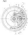
- the watch movement 1 represented in FIG. 1 comprises a date indicator member 3 in the form of a crown having an internal toothing, and a day indicator member in the form of a disc which has not been shown for reasons of clarity.
- the day disc is conventionally provided to be driven by the intermediary of a 5 day star to which it is integral. In a conventional manner, the movement is provided for driving both the date ring and the day disc by one step per twenty-four hours.
- Movement 1 further includes a date correction mechanism controlled by a control rod 7 movable between three axial positions.
- the rod 7 carries a sliding pinion 9 conventionally actuated by a rocker 10.
- This rocker is articulated on the frame of the movement 1 at a point 11 and comprises an arm 10b acting as a return spring.
- the lever 10 is controlled, still in a conventional manner, by a pull rod 13 articulated on the frame at a point 14, and which comprises an end portion 13a engaged in a groove 15 of the rod 7.
- the rod 7 further carries, mounted idly on it, a correcting pinion 17 of the date and date indicating members 3.
- the correcting pinion 17 is mounted so as to permanently mesh with a first reference referenced 19 in FIG. 1 and, in accordance with what will be explained in more detail below, it is intended to be driven in rotation by the sliding pinion 9 when the rod 7 is in a first pulled position (FIG. 2b).
- the first gear 19 in turn meshes with a wandering gear 21 which, conventionally, depending on the direction of rotation imposed on it, will be placed either in a first position where it meshes with the internal toothing of the ring of date 3, or in a second position where it drives, through a gear train 23, the day star 5.
- the sliding pinion 9 cooperates with the corrector pinion 17 to drive the latter in rotation.
- the faces of the sliding pinion 9 and the correcting pinion 17 which are opposite one another, are shaped to be able to cooperate by engagement with each other.
- the corrector pinion 17 is shown seen from the front. We see that it has the general shape of a flat disc.
- the periphery of the pinion has a toothing 22 of conventional type, while its center is pierced with a hole 24 comprising a circular central portion and two notches 25a and 25b arranged diametrically opposite one another.
- This gable has the advantage of being able to be cut, in a single stamping operation, from a simple sheet metal plate.
- the circular central portion of the hole 24 is provided to receive the control rod 7 whose diameter is substantially equal to that of this circular part. A minimal play allows the rod 7 to rotate freely in the circular part while allowing the centered positioning of the correcting pinion on the rod.
- the two notches 25a and 25b form two openings located on either side of the axis of the rod 7. As will be seen below, these two openings are provided for cooperate in accordance with the invention with pins 28a and 28b provided for this purpose on the sliding pinion 9.
- Figures 4 and 5 show the sliding pinion 9 respectively from the front and in longitudinal section. It can be seen that, apart from the two pins 28a and 28b, the sliding pinion has a classic shape. This shape is externally that of a part of revolution which can be obtained from a block of metal by conventional turning operations.
- the sliding pinion is therefore preferably first produced, by turning, a fully symmetrical part in rotation.
- This part does not yet contain the two lugs 28a and 28b, but it does, however, have a crown 30 whose outline is marked by a broken line in Figures 4 and 5.
- the two pins 28a and 28b are formed by milling the material constituting the crown 30. Two millings are sufficient to remove the material forming the two crown portions respectively (referenced 30a and 30b in FIG. 4) and to release the two pins 28a and 28b. Thanks to this way of proceeding, the production of the sliding pinion of the timepiece according to the present invention is particularly simple and inexpensive.
- FIGS. 2a and 2b show how the lever 32 controls the longitudinal positioning of the sliding pinion 9 along the control rod 7.
- the control rod 7 is brought from the neutral position (pushed position shown in FIG. 2a) to the date correction position (first drawn position shown in FIG. 2b)
- the two pins 28a and 28b of the sliding pinion 9 bear against the face of the correcting pinion 17.
- This correcting pinion comprises, as we have already said, two notches 25a and 25b which are respectively designed to receive the two pins of the sliding pinion.
- the two pins 28a and 28b are generally not located just opposite the notches 25a and 25b when the control rod is pulled. In the most common case, the two pins therefore press against the face of the correcting pinion 17 without engaging in the two notches thereof. In this position, when the rod 7 is rotated, the sliding pinion 9 which is integral with it in rotation, will be able to rotate without rotating the correcting pinion. Under these conditions, the two pins of the sliding pinion will slide against the surface of the correcting pinion until they meet the two notches 25a and 25b and they engage in it. Under these conditions, a rotation of a fraction of a turn effected by the rod 7 will suffice to cause the sliding pinion 9 to lock in rotation with the corrector pinion 17.
Landscapes
- Physics & Mathematics (AREA)
- General Physics & Mathematics (AREA)
- Electromechanical Clocks (AREA)
- Gears, Cams (AREA)
- Transmission Devices (AREA)
Abstract
Description
- La présente invention concerne une pièce d'horlogerie comportant au moins un organe indicateur, notamment des quantièmes, et un mécanisme de correction de cet organe indicateur, ledit mécanisme de correction comprenant au moins, d'une part, une tige de commande mobile entre au moins deux positions axiales et, d'autre part, un pignon coulant et un pignon correcteur montés sur ladite tige, ledit pignon correcteur étant libre en rotation et une de ses faces étant conformée pour pouvoir coopérer avec une des faces du pignon coulant et permettre l'entraînement dudit pignon correcteur par le pignon coulant lorsque ladite tige de commande se trouve dans une première desdites positions axiales.
- De telles pièces d'horlogerie sont connues en soi. Dans ces pièces d'horlogerie, le pignon coulant et le pignon correcteur présentent, le plus souvent, chacun une denture de chant et l'entraînement du pignon correcteur est assuré par la coopération de ces deux dentures. Ce type de construction présente toutefois des inconvénients. En effet, la réalisation d'une denture de chant sur un pignon implique des opérations d'usinage relativement complexes et donc relativement coûteuses également.
- Un but de la présente invention est donc de remédier à l'inconvénient qui vient d'être décrit en fournissant un mouvement d'horlogerie dans lequel la fabrication du mécanisme de correction et rendue plus simple et plus économique. A cette effet, la présente invention a pour objet une pièce d'horlogerie comportant au moins un organe indicateur, notamment des quantièmes, et un mécanisme de correction de cet organe indicateur, ledit mécanisme de correction comprenant au moins, d'une part, une tige de commande mobile entre au moins deux positions axiales et, d'autre part, un pignon coulant et un pignon correcteur montés sur ladite tige, ledit pignon correcteur étant libre en rotation et une de ses faces étant conformée pour pouvoir coopérer avec une des faces du pignon coulant et permettre l'entraînement dudit pignon correcteur par le pignon coulant lorsque ladite tige de commande se trouve dans une première desdites positons axiales, caractérisée en ce que ladite face du pignon coulant présente au moins un ergot disposé à distance de l'axe de rotation dudit pignon coulant et en ce que ledit ergot est prévu pour venir s'engager dans une ouverture formée dans ladite face dudit pignon correcteur, pour coopérer avec un bord de celle-ci de manière à entraîner ledit pignon correcteur en rotation.
- Grâce à ces caractéristiques, il n'est plus nécessaire de réaliser une denture de chant sur le pignon correcteur, et ladite ouverture formée dans la face de celui-ci et qui remplace la denture de chant, peut être réalisée simplement par étampage. De plus, ledit ergot formé sur la face du pignon coulant est plus facile à réaliser qu'une denture de chant complète.
- Selon une caractéristique avantageuse de l'invention, le pignon correcteur se présente sous la forme d'un simple disque dentelé percé en son centre d'un trou généralement circulaire dans lequel est engagée la tige de commande, la périphérie dudit trou comportant encore au moins une encoche prévue pour recevoir ledit ergot du pignon coulant.
- Selon une autre caractéristique avantageuse de l'invention, la périphérie dudit trou généralement circulaire pratiqué dans le pignon correcteur présente deux encoches disposées diamétralement à l'opposé l'une de l'autre, alors que le pignon coulant comporte deux ergots disposés symétriquement de part et d'autre de ladite tige de commande et prévus pour s'engager respectivement dans les deux encoches.
- D'autres caractéristiques et avantages de la présente invention apparaîtront au cours de la description qui va suivre, donnée uniquement à titre d'exemple et faite en se référant aux dessins annexés dans lesquels:
- la figure 1 est une vue en plan d'un mouvement de montre calendrier selon l'invention dans laquelle on a représenté seulement les organes de correction de la date;
- les figures 2a et 2b sont des vues de l'organe de commande du mouvement de la figure 1, montrant respectivement celui-ci en position neutre (position poussée) et en position de correction de la date (première position tirée);
- la figure 3 est une vue en plan du pignon correcteur du mouvement de la figure 1;
- les figures 4 et 5 sont deux vues respectivement de face et en coupe du pignon coulant du mouvement de la figure 1.
- Le mouvement de montre 1 représenté sur la figure 1 comprend un organe indicateur du quantième 3 en forme d'une couronne présentant une denture intérieure, et un organe indicateur du jour en forme de disque qui n'a pas été représenté pour des raisons de clarté. Le disque des jours est, de façon classique, prévu pour être entraîné par l'intermédiaire d'une étoile des jours 5 dont il est solidaire. De façon classique le mouvement est prévu pour entraîner aussi bien l'anneau des quantièmes que le disque des jours d'un pas par vingt-quatre heures.
- Le mouvement 1 comporte en outre un mécanisme de correction de la date commandé par une tige de commande 7 mobile entre trois positions axiales. La tige 7 porte un pignon coulant 9 actionné de façon classique par une bascule 10. Cette bascule est articulée sur le bâti du mouvement 1 en un point 11 et comporte un bras 10b faisant office de ressort de rappel. La bascule 10 est commandée, toujours de façon classique, par une tirette 13 articulée sur le bâti en un point 14, et qui comporte une partie terminale 13a engagée dans une gorge 15 de la tige 7.
- La tige 7 porte en outre, monté fou sur elle, un pignon correcteur 17 des organes indicateurs du jour et du quantième 3. Le pignon correcteur 17 est monté de façon à engréner en permanence avec un premier renvoi référencé 19 sur la figure 1 et, conformément à ce qui sera expliqué plus en détails ci-après, il est prévu pour être entraîné en rotation par le pignon coulant 9 lorsque la tige 7 se trouve dans une première position tirée (figure 2b). Le premier renvoi 19 engrène à son tour avec un renvoi baladeur 21 qui, de façon classique, selon le sens de rotation qu'on lui impose, va se placer soit dans une première position où il engrène avec la denture intérieure de l'anneau des quantièmes 3, soit dans une deuxième position où il entraîne, par l'intermédiaire d'un rouage 23, l'étoile des jours 5.
- On comprendra que, grâce à cette construction, lorsque la tige de commande 7 est placée dans la première position tirée, on corrige l'indication du quantième en faisant tourner la tige dans un premier sens, et on corrige l'indication du jour en la faisant tourner dans l'autre sens.
- Comme nous l'avons déjà dit, lorsque la tige de commande 7 se trouve dans la première position tirée (fig. 2b), le pignon coulant 9 coopère avec le pignon correcteur 17 pour entraîner celui-ci en rotation. A cet effet, les faces du pignon coulant 9 et du pignon correcteur 17 qui sont en regard l'une de l'autre, sont conformées pour pouvoir coopérer par engagement l'une avec l'autre.
- Sur la figure 3, le pignon correcteur 17 est représenté vu de face. On voit qu'il a la forme générale d'un disque plat. La périphérie du pignon présente une denture 22 de type classique, alors que son centre est percé d'un trou 24 comportant une portion centrale circulaire et deux encoches 25a et 25b disposées diamétralement à l'opposé l'une de l'autre. Ce pignon présente l'avantage de pouvoir être découpé, en une seule opération d'étampage, dans une simple plaque de tôle.
- La portion centrale circulaire du trou 24 est prévue pour recevoir la tige de commande 7 dont le diamètre est sensiblement égal à celui de cette partie circulaire. Un jeu minime permet à la tige 7 de tourner librement dans la partie circulaire tout en permettant le positionnement centré du pignon correcteur sur la tige. Lorsque le pignon 17 est monté sur la tige 7, les deux encoches 25a et 25b forment deux ouvertures situées de part et d'autre de l'axe de la tige 7. Comme on va le voir plus loin, ces deux ouvertures sont prévues pour coopérer conformément à l'invention avec des ergots 28a et 28b ménagés à cet effet sur le pignon coulant 9.
- Les figures 4 et 5 représentent le pignon coulant 9 respectivement de face et en coupe longitudinale. On voit que, abstraction faite des deux ergots 28a et 28b, le pignon coulant présente une forme classique. Cette forme est extérieurement celle d'une pièce de révolution qui peut être obtenue à partir d'un bloc de métal par des opérations conventionnelles de tournage.
- Pour fabriquer le pignon coulant selon l'invention, on réalise donc de préférence d'abord, par tournage, une pièce entièrement symétrique en rotation. Cette pièce ne contient pas encore les deux ergots 28a et 28b, mais elle comporte en revanche une couronne 30 dont le contour est repéré par un trait interrompu sur les figures 4 et 5. C'est, lors d'une étape ultérieure que l'on forme, par fraisage de la matière constituant la couronne 30, les deux ergots 28a et 28b. Il suffit de deux fraisages pour enlever respectivement la matière formant les deux portions de couronne (référencées 30a et 30b sur la figure 4) et pour dégager les deux ergots 28a et 28b. Grâce à cette façon de procéder, la réalisation du pignon coulant de la pièce d'horlogerie selon la présente invention est particulièrement simple et bon marché.
- Comme cela est visible en particulier sur les figures 2a et 2b, lorsque le pignon coulant 9 est monté dans le mouvement 1, la face de celui-ci, qui porte les deux ergots 28a et 28b, se trouve en regard du pignon correcteur 17. Les figures 2a et 2b montrent comment la bascule 32 commande le positionnement longitudinal du pignon coulant 9 le long de la tige de commande 7. Lorsqu'on amène la tige de commande 7 de la position neutre (position poussée représentée à la figure 2a) à la position de correction de la date (première position tirée représentée à la figure 2b), les deux ergots 28a et 28b du pignon coulant 9 viennent s'appuyer contre la face du pignon correcteur 17. Ce pignon correcteur comporte, comme nous l'avons déjà dit, deux encoches 25a et 25b qui sont respectivement prévues pour recevoir les deux ergots du pignon coulant. Toutefois, les deux ergots 28a et 28b ne se trouvent généralement pas juste en face des encoches 25a et 25b au moment où l'on tire sur la tige de commande. Dans le cas le plus courant, les deux ergots viennent donc appuyer contre la face du pignon correcteur 17 sans s'engager dans les deux encoches de celui-ci. Dans cette position, lorsqu'on tourne la tige 7, le pignon coulant 9 qui lui est solidaire en rotation, va pouvoir tourner sans entraîner en rotation le pignon correcteur. Dans ces conditions, les deux ergots du pignon coulant vont glisser contre la surface du pignon correcteur jusqu'à ce qu'ils rencontrent les deux encoches 25a et 25b et qu'ils s'engagent dans celle-ci. Dans ces conditions, une rotation d'une fraction de tour effectuée par la tige 7, suffira pour provoquer le verrouillage en rotation du pignon coulant 9 avec le pignon correcteur 17.
Claims (3)
- Pièce d'horlogerie comportant au moins un organe indicateur (3), notamment des quantièmes, et un mécanisme de correction de cet organe indicateur, ledit mécanisme de correction comprenant au moins, d'une part, une tige de commande (7) mobile entre au moins deux positions axiales et, d'autre part, un pignon coulant (9) et un pignon correcteur (17) montés sur ladite tige, ledit pignon correcteur étant libre en rotation et une de ses faces étant conformée pour pouvoir coopérer avec une des faces du pignon coulant (9) et permettre l'entraînement dudit pignon correcteur par le pignon coulant lorsque ladite tige de commande (7) se trouve dans une première desdites positons axiales, caractérisée en ce que ladite face du pignon coulant présente au moins un ergot disposé à distance de l'axe de rotation dudit pignon coulant et en ce que ledit ergot (28) est prévu pour venir s'engager dans une ouverture formée (25) dans ladite face dudit pignon correcteur, pour coopérer avec un bord de celle-ci de manière à entraîner ledit pignon correcteur en rotation.
- Pièce d'horlogerie selon la revendication 1, caractérisée en ce que ledit pignon correcteur (17) se présente sous la forme d'un disque dentelé percé en son centre d'un trou généralement circulaire (24) dans lequel est engagé ladite tige de commande (7), et en ce que la périphérie dudit trou généralement circulaire (24) comporte au moins une encoche (25) prévue pour recevoir ledit ergot (28) du pignon coulant.
- Pièce d'horlogerie selon la revendication 2, caractérisée en ce que la périphérie dudit trou généralement circulaire (24) comporte deux encoches (25a, 25b) disposées diamétralement à l'opposé l'une de l'autre, et en ce que le pignon coulant comporte deux ergots (28a, 28b) disposés symétriquement de part et d'autre de ladite tige (7) de commande et prévu pour s'engager respectivement dans lesdites deux encoches.
Applications Claiming Priority (2)
| Application Number | Priority Date | Filing Date | Title |
|---|---|---|---|
| CH2585/93 | 1993-08-31 | ||
| CH2585/93A CH684920B5 (fr) | 1993-08-31 | 1993-08-31 | Pièce d'horlogerie. |
Publications (2)
| Publication Number | Publication Date |
|---|---|
| EP0640892A1 true EP0640892A1 (fr) | 1995-03-01 |
| EP0640892B1 EP0640892B1 (fr) | 1997-11-12 |
Family
ID=4237104
Family Applications (1)
| Application Number | Title | Priority Date | Filing Date |
|---|---|---|---|
| EP94113410A Expired - Lifetime EP0640892B1 (fr) | 1993-08-31 | 1994-08-26 | Pièce d'horlogerie |
Country Status (7)
| Country | Link |
|---|---|
| US (1) | US5392260A (fr) |
| EP (1) | EP0640892B1 (fr) |
| JP (1) | JPH07151867A (fr) |
| CN (1) | CN1047004C (fr) |
| CH (1) | CH684920B5 (fr) |
| DE (1) | DE69406738T2 (fr) |
| SG (1) | SG87732A1 (fr) |
Cited By (1)
| Publication number | Priority date | Publication date | Assignee | Title |
|---|---|---|---|---|
| EP1862871A1 (fr) * | 2006-05-31 | 2007-12-05 | Montres Breguet S.A. | Pièce d'horlogerie comportant un dispositif de mise à l'heure amélioré |
Families Citing this family (8)
| Publication number | Priority date | Publication date | Assignee | Title |
|---|---|---|---|---|
| EP1152303B1 (fr) * | 2000-05-05 | 2006-07-19 | Rolex Sa | Montre à mécanisme de remontage et de correction d'au moins deux organes indicateurs |
| JP4462606B2 (ja) * | 2004-01-27 | 2010-05-12 | セイコーインスツル株式会社 | 表示修正機構付き時計 |
| DE602006013838D1 (de) * | 2006-11-06 | 2010-06-02 | Longines Montres Comp D | Uhr, die einen Korrekturmechanismus für eine Vorrichtung zur Anzeige einer Zeitgröße umfasst |
| EP1939699B1 (fr) * | 2006-12-29 | 2012-05-30 | Montres Breguet S.A. | Dispositif correcteur coaxial multifonction |
| EP2096504B1 (fr) * | 2008-02-29 | 2011-11-16 | Manufacture La Joux-Perret SA | Mécanisme d'affichage des secondes mortes |
| EP3193217A1 (fr) * | 2016-01-18 | 2017-07-19 | ETA SA Manufacture Horlogère Suisse | Mouvement horloger comprenant un affichage analogique |
| CH714795A9 (fr) * | 2018-03-16 | 2020-01-15 | Lvmh Swiss Mft Sa | Pièce d'horlogerie comprenant un mécanisme de correction des indications fournies par un premier et deuxième organe d'affichage. |
| EP3629102B1 (fr) * | 2018-09-26 | 2022-12-14 | Patek Philippe SA Genève | Mécanisme d'affichage à guichet unique |
Citations (3)
| Publication number | Priority date | Publication date | Assignee | Title |
|---|---|---|---|---|
| US567409A (en) * | 1896-09-08 | Wilson e | ||
| US3609955A (en) * | 1969-02-20 | 1971-10-05 | Citizen Watch Co Ltd | Quick calender correction mechanism of timepiece |
| EP0212564A1 (fr) * | 1985-08-20 | 1987-03-04 | Eta SA Fabriques d'Ebauches | Mécanisme de mise à l'heure pour pièce d'horlogerie |
Family Cites Families (3)
| Publication number | Priority date | Publication date | Assignee | Title |
|---|---|---|---|---|
| CH524846A (de) * | 1968-10-11 | 1972-03-15 | Centre Electron Horloger | Kalenderuhr |
| CH1913970A4 (fr) * | 1970-12-23 | 1973-04-13 | ||
| JPS594302Y2 (ja) * | 1978-04-19 | 1984-02-07 | セイコーエプソン株式会社 | 時計の切換機構 |
-
1993
- 1993-08-31 CH CH2585/93A patent/CH684920B5/fr not_active IP Right Cessation
-
1994
- 1994-07-21 US US08/278,330 patent/US5392260A/en not_active Expired - Fee Related
- 1994-08-26 SG SG9602565A patent/SG87732A1/en unknown
- 1994-08-26 EP EP94113410A patent/EP0640892B1/fr not_active Expired - Lifetime
- 1994-08-26 DE DE69406738T patent/DE69406738T2/de not_active Expired - Fee Related
- 1994-08-30 JP JP6205343A patent/JPH07151867A/ja active Pending
- 1994-08-30 CN CN94115608A patent/CN1047004C/zh not_active Expired - Fee Related
Patent Citations (3)
| Publication number | Priority date | Publication date | Assignee | Title |
|---|---|---|---|---|
| US567409A (en) * | 1896-09-08 | Wilson e | ||
| US3609955A (en) * | 1969-02-20 | 1971-10-05 | Citizen Watch Co Ltd | Quick calender correction mechanism of timepiece |
| EP0212564A1 (fr) * | 1985-08-20 | 1987-03-04 | Eta SA Fabriques d'Ebauches | Mécanisme de mise à l'heure pour pièce d'horlogerie |
Cited By (2)
| Publication number | Priority date | Publication date | Assignee | Title |
|---|---|---|---|---|
| EP1862871A1 (fr) * | 2006-05-31 | 2007-12-05 | Montres Breguet S.A. | Pièce d'horlogerie comportant un dispositif de mise à l'heure amélioré |
| US7654731B2 (en) | 2006-05-31 | 2010-02-02 | Montres Breguet S.A. | Timepiece comprising an improved time-setting device |
Also Published As
| Publication number | Publication date |
|---|---|
| CN1047004C (zh) | 1999-12-01 |
| CN1103966A (zh) | 1995-06-21 |
| JPH07151867A (ja) | 1995-06-16 |
| US5392260A (en) | 1995-02-21 |
| EP0640892B1 (fr) | 1997-11-12 |
| CH684920B5 (fr) | 1995-08-15 |
| DE69406738T2 (de) | 1998-06-04 |
| DE69406738D1 (de) | 1997-12-18 |
| SG87732A1 (en) | 2002-04-16 |
| CH684920GA3 (fr) | 1995-02-15 |
Similar Documents
| Publication | Publication Date | Title |
|---|---|---|
| EP0548659B1 (fr) | Pièce d'horlogerie du type mécanique ou électromécanique comportant une roue d'entraînement pilotant au moins un système d'affichage, tel qu'un affichage des quantièmes | |
| EP0549941B1 (fr) | Pièce d'horlogerie du type mécanique et/ou électromécanique, pourvue de moyens d'affichage à déplacement retrograde automatique | |
| EP2012199B2 (fr) | Pièce d'horlogerie munie d'un dispositif de commande de fonctions et/ou d'indications horaires | |
| EP3144743B1 (fr) | Mouvement horloger comprenant un mécanisme de correction de la date | |
| EP2701014A1 (fr) | Bascule d'embrayage et dispositif d'embrayage pour mécanisme horloger | |
| EP1978420B1 (fr) | Roue d'horlogerie et dispositif de correction d'un mécanisme d'affichage pour pièce d'horlogerie incorporant une telle roue | |
| EP0640892B1 (fr) | Pièce d'horlogerie | |
| EP0987609B1 (fr) | Mécanisme de quantième annuel pour mouvement d'horlogerie | |
| EP0075535A1 (fr) | Dispositif de commande des fonctions d'une montre permettant l'affichage de l'état d'au moins une des fonctions commandées | |
| CH688495B5 (fr) | Pièce d'horlogerie comportant un mécanisme de commande à tige et à tirette. | |
| EP2707778B1 (fr) | Piece d'horlogerie | |
| EP0212564B1 (fr) | Mécanisme de mise à l'heure pour pièce d'horlogerie | |
| EP0479147B1 (fr) | Pièce d'horlogerie du type mécanique et/ou électromécanique | |
| EP0563745B1 (fr) | Mouvement d'horlogerie comportant des moyens de quidage d'un organe de commande, tel qu'une tige | |
| EP4375763B1 (fr) | Mouvement horloger comprenant un mecanisme de correction d'un affichage | |
| EP4012505B1 (fr) | Dispositif horloger à mobile antiblocage | |
| CH720264A2 (fr) | Mouvement horloger comprenant un mécanisme de correction d'un affichage | |
| EP1538494A1 (fr) | Mécanisme de commande d'une montre mécanique | |
| EP0063543A1 (fr) | Pièce d'horlogerie à mécanisme de commande | |
| EP1925996A1 (fr) | Dispositif de correction d'un mécanisme d'affichage pour pièce d'horlogerie | |
| EP0065016B1 (fr) | Montre dont le fond de la boîte constitue une platine | |
| EP4592766A1 (fr) | Dispositif horloger de commande | |
| CH684980B5 (fr) | Mouvement de montre comprenant une plaque de maintien d'un organe indicateur. | |
| CH720894A2 (fr) | Mécanisme horloger comprenant une came | |
| CH648449GA3 (en) | Watch movement including a calendar driven in synchronism with the hour hand, a time-correction mechanism and a time-setting mechanism |
Legal Events
| Date | Code | Title | Description |
|---|---|---|---|
| PUAI | Public reference made under article 153(3) epc to a published international application that has entered the european phase |
Free format text: ORIGINAL CODE: 0009012 |
|
| AK | Designated contracting states |
Kind code of ref document: A1 Designated state(s): DE FR GB |
|
| 17P | Request for examination filed |
Effective date: 19950314 |
|
| 17Q | First examination report despatched |
Effective date: 19960429 |
|
| GRAG | Despatch of communication of intention to grant |
Free format text: ORIGINAL CODE: EPIDOS AGRA |
|
| GRAH | Despatch of communication of intention to grant a patent |
Free format text: ORIGINAL CODE: EPIDOS IGRA |
|
| GRAH | Despatch of communication of intention to grant a patent |
Free format text: ORIGINAL CODE: EPIDOS IGRA |
|
| GRAA | (expected) grant |
Free format text: ORIGINAL CODE: 0009210 |
|
| AK | Designated contracting states |
Kind code of ref document: B1 Designated state(s): DE FR GB |
|
| REF | Corresponds to: |
Ref document number: 69406738 Country of ref document: DE Date of ref document: 19971218 |
|
| GBT | Gb: translation of ep patent filed (gb section 77(6)(a)/1977) |
Effective date: 19980122 |
|
| PLBE | No opposition filed within time limit |
Free format text: ORIGINAL CODE: 0009261 |
|
| STAA | Information on the status of an ep patent application or granted ep patent |
Free format text: STATUS: NO OPPOSITION FILED WITHIN TIME LIMIT |
|
| 26N | No opposition filed | ||
| REG | Reference to a national code |
Ref country code: GB Ref legal event code: IF02 |
|
| PGFP | Annual fee paid to national office [announced via postgrant information from national office to epo] |
Ref country code: GB Payment date: 20020730 Year of fee payment: 9 |
|
| PGFP | Annual fee paid to national office [announced via postgrant information from national office to epo] |
Ref country code: FR Payment date: 20020828 Year of fee payment: 9 |
|
| PGFP | Annual fee paid to national office [announced via postgrant information from national office to epo] |
Ref country code: DE Payment date: 20030808 Year of fee payment: 10 |
|
| PG25 | Lapsed in a contracting state [announced via postgrant information from national office to epo] |
Ref country code: GB Free format text: LAPSE BECAUSE OF NON-PAYMENT OF DUE FEES Effective date: 20030826 |
|
| GBPC | Gb: european patent ceased through non-payment of renewal fee | ||
| PG25 | Lapsed in a contracting state [announced via postgrant information from national office to epo] |
Ref country code: FR Free format text: LAPSE BECAUSE OF NON-PAYMENT OF DUE FEES Effective date: 20040430 |
|
| REG | Reference to a national code |
Ref country code: FR Ref legal event code: ST |
|
| PG25 | Lapsed in a contracting state [announced via postgrant information from national office to epo] |
Ref country code: DE Free format text: LAPSE BECAUSE OF NON-PAYMENT OF DUE FEES Effective date: 20050301 |