EP0640924A2 - Vorrichtung zur Wiedergabe von Daten - Google Patents
Vorrichtung zur Wiedergabe von Daten Download PDFInfo
- Publication number
- EP0640924A2 EP0640924A2 EP94112775A EP94112775A EP0640924A2 EP 0640924 A2 EP0640924 A2 EP 0640924A2 EP 94112775 A EP94112775 A EP 94112775A EP 94112775 A EP94112775 A EP 94112775A EP 0640924 A2 EP0640924 A2 EP 0640924A2
- Authority
- EP
- European Patent Office
- Prior art keywords
- data
- recording medium
- reproducing
- recorded
- vendor unique
- Prior art date
- Legal status (The legal status is an assumption and is not a legal conclusion. Google has not performed a legal analysis and makes no representation as to the accuracy of the status listed.)
- Withdrawn
Links
Images


Classifications
-
- G—PHYSICS
- G11—INFORMATION STORAGE
- G11B—INFORMATION STORAGE BASED ON RELATIVE MOVEMENT BETWEEN RECORD CARRIER AND TRANSDUCER
- G11B20/00—Signal processing not specific to the method of recording or reproducing; Circuits therefor
- G11B20/00086—Circuits for prevention of unauthorised reproduction or copying, e.g. piracy
- G11B20/00166—Circuits for prevention of unauthorised reproduction or copying, e.g. piracy involving measures which result in a restriction to authorised contents recorded on or reproduced from a record carrier, e.g. music or software
-
- G—PHYSICS
- G11—INFORMATION STORAGE
- G11B—INFORMATION STORAGE BASED ON RELATIVE MOVEMENT BETWEEN RECORD CARRIER AND TRANSDUCER
- G11B11/00—Recording on or reproducing from the same record carrier wherein for these two operations the methods are covered by different main groups of groups G11B3/00 - G11B7/00 or by different subgroups of group G11B9/00; Record carriers therefor
- G11B11/03—Recording on or reproducing from the same record carrier wherein for these two operations the methods are covered by different main groups of groups G11B3/00 - G11B7/00 or by different subgroups of group G11B9/00; Record carriers therefor using recording by deforming with non-mechanical means, e.g. laser, beam of particles
-
- G—PHYSICS
- G11—INFORMATION STORAGE
- G11B—INFORMATION STORAGE BASED ON RELATIVE MOVEMENT BETWEEN RECORD CARRIER AND TRANSDUCER
- G11B19/00—Driving, starting, stopping record carriers not specifically of filamentary or web form, or of supports therefor; Control thereof; Control of operating function ; Driving both disc and head
- G11B19/02—Control of operating function, e.g. switching from recording to reproducing
-
- G—PHYSICS
- G11—INFORMATION STORAGE
- G11B—INFORMATION STORAGE BASED ON RELATIVE MOVEMENT BETWEEN RECORD CARRIER AND TRANSDUCER
- G11B20/00—Signal processing not specific to the method of recording or reproducing; Circuits therefor
- G11B20/00086—Circuits for prevention of unauthorised reproduction or copying, e.g. piracy
- G11B20/00188—Circuits for prevention of unauthorised reproduction or copying, e.g. piracy involving measures which result in a restriction to authorised devices recording or reproducing contents to/from a record carrier
-
- G—PHYSICS
- G11—INFORMATION STORAGE
- G11B—INFORMATION STORAGE BASED ON RELATIVE MOVEMENT BETWEEN RECORD CARRIER AND TRANSDUCER
- G11B20/00—Signal processing not specific to the method of recording or reproducing; Circuits therefor
- G11B20/10—Digital recording or reproducing
- G11B20/18—Error detection or correction; Testing, e.g. of drop-outs
- G11B20/1833—Error detection or correction; Testing, e.g. of drop-outs by adding special lists or symbols to the coded information
-
- G—PHYSICS
- G11—INFORMATION STORAGE
- G11B—INFORMATION STORAGE BASED ON RELATIVE MOVEMENT BETWEEN RECORD CARRIER AND TRANSDUCER
- G11B20/00—Signal processing not specific to the method of recording or reproducing; Circuits therefor
- G11B20/10—Digital recording or reproducing
- G11B20/18—Error detection or correction; Testing, e.g. of drop-outs
- G11B20/1883—Methods for assignment of alternate areas for defective areas
-
- G—PHYSICS
- G06—COMPUTING OR CALCULATING; COUNTING
- G06F—ELECTRIC DIGITAL DATA PROCESSING
- G06F11/00—Error detection; Error correction; Monitoring
- G06F11/07—Responding to the occurrence of a fault, e.g. fault tolerance
- G06F11/08—Error detection or correction by redundancy in data representation, e.g. by using checking codes
- G06F11/10—Adding special bits or symbols to the coded information, e.g. parity check, casting out 9's or 11's
- G06F11/1008—Adding special bits or symbols to the coded information, e.g. parity check, casting out 9's or 11's in individual solid state devices
-
- G—PHYSICS
- G06—COMPUTING OR CALCULATING; COUNTING
- G06F—ELECTRIC DIGITAL DATA PROCESSING
- G06F2211/00—Indexing scheme relating to details of data-processing equipment not covered by groups G06F3/00 - G06F13/00
- G06F2211/007—Encryption, En-/decode, En-/decipher, En-/decypher, Scramble, (De-)compress
-
- G—PHYSICS
- G11—INFORMATION STORAGE
- G11B—INFORMATION STORAGE BASED ON RELATIVE MOVEMENT BETWEEN RECORD CARRIER AND TRANSDUCER
- G11B2220/00—Record carriers by type
- G11B2220/20—Disc-shaped record carriers
Definitions
- This invention relates to a data reproducing apparatus, and more particularly to an improvement of optical disc device which is utilized as an auxiliary memory unit for a computer.
- optical disc device which is used as an auxiliary memory unit for a computer, etc..
- optical disc device there are optical disc devices for reproducing only which uses unwritable optical disc, an optical disc device which uses writable optical disc, for example, magnetic optical disc, and the like.
- DDS Disc Definition Structure
- information of sector interchange-processed, etc. is recorded in the DDS.
- the DDS is so important data as to be recorded twice each in the innermost and the outermost of an optical disc. If one data becomes impossible to correct error, the data structure can be obtained from another DDS recorded in another area.
- an object of this invention is to provide a data reproducing apparatus for solving the above problems.
- this invention provides a disc driving apparatus for driving a disc type recording medium on which a vendor unique data which can not be output to outside the disc driving apparatus and an user data are recorded, comprising: reproducing means for reproducing the vendor unique data and the user data recorded on the disc type recording medium; buffer memory means for temporary storing the user data reproduced by the reproducing means; interface means for outputting the user data to outside the disc driving apparatus, identification data storing means for storing an identification data which is peculiar to the disc driving apparatus; detection means for detecting whether or not the vendor unique data reproduced by the reproducing means is coincident with the identification data; and control means for preventing outputting of the user data from the interface means when the detection means detects that the vender unique data is not coincident with the identification data.
- this invention provides a disc driving apparatus for driving a disc type recording medium on which a vendor unique data which can not be output to outside the disc driving apparatus, a structure data which indicates a data structure of the disc type recording medium and an user data are recorded, comprising: reproducing means for reproducing the vendor unique data, the structure data, and the user data recorded on the disc type recording medium; interface means for outputting the user data to outside the disc driving apparatus; identification data storing means for storing an identification data which is peculiar to the disc driving apparatus; detection means for detecting whether or not the vendor unique data reproduced from each logical address of the disc type recording medium is coincident with the identification data; and means for rearranging the logical address of the disc type recording medium on the basis of an output signal of the detection means.
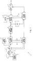
- Fig. 1, 1 denotes an optical disc device, which records and/or reproduces the desired data by utilizing an optical disc 2 capable of recording and/or reproducing, and also reproduces the desired data from a reproduction only optical disc 2.
- an optical-magnetic disc which is able to record and/or reproduce the desired data by applying the thermomagnetic recording scheme and a ROM (read only memory) disc for reproduction which has been produced by applying the same scheme as the compact disc, are applicable.
- a spindle motor S is driven by a spindle motor control circuit 3, so that an optical disc 2 is rotated with a predetermined rotating speed.
- a laser control circuit 4 is caused to project a light beam from an optical pick-up 5 to the optical disc 2, by driving a laser diode which is included in the optical pick-up 5.
- the optical pick-up 5 receives a reflected light of this light beam on the light-receiving element, and then outputs the result of the light-receiving to an RF signal processing circuit 6.
- the RF signal processing circuit 6 performs a current-voltage transforming process of this result of the light-receiving and then performs an add-subtract processing at the stated matrix circuit, in order to generate a tracking error signal TE and a focus error signal FE, and then outputs the tracking error signal TE and the focus error signal FE to a servo control circuit 7.
- the servo control circuit 7 moves the optical pick-up 5 and an object lens which is included in the optical pick-up 5, based on the tracking error signal TE and the focus error signal FE, so as to perform a tracking controlling and a focus controlling.
- the servo control circuit 7 cause the optical pick-up 5 to seek in radial direction of the optical disc, in response to a control command which is outputted from a system control circuit 9, so as to access the optical disc 2.
- the RF signal processing circuit 6 generates a reproducing signal (composed of a so-called “sum signal”) of which signal level changes in accordance with a quantity of light of the reflected light, and a reproducing signal (composed of a so-called “difference signal”) of which signal level changes in accordance with a change of a polarization surface of the reflected light, respectively.
- the optical disc device 1 reproduces the desired data, and also detects a logical address of the reproducing position (that is composed of a physical address).
- the optical disc device 1 reproduces the desired data, in addition, by taking the sum signal at the specified period and processing it, the optical disc device 1 detects the logical address of the recording and/or reproducing position.
- the system control circuit 9 makes the optical pick-up 5 to seek, by issuing a control code to the servo control circuit 7 on the basis of thus detected logical address.
- the data modulating and decoding circuit 8 obtains the reproducing data by performing a binarization of the reproducing signal outputted from the RF signal processing circuit 6 and then performing a 7-2 demodulation, and outputs this reproducing data to a buffer control circuit 10.
- an error detecting and correcting circuit (ECC) 11 performs an error correcting process on this reproducing data, utilizing an error detecting and correcting code which is reproduced along with the reproducing data.
- the error detecting and correcting circuit 11 outputs the result of the error correction to the system control circuit 9.
- the system control circuit 9 judges whether the desired data has been correctly reproduced or not, and issues a control code, if necessary, so as to repeat the reproducing operation.
- the system control circuit 9 issues an error code, which represents that an error has occurred, to a host computer by an interruption through a SCSI (small computer system interface) interface circuit (I/F) 12.
- SCSI small computer system interface
- the buffer control circuit 10 sequentially inputs and stores the reproducing data into a buffer memory 13, and then outputs the reproducing data which has been stored in the buffer memory 13 to the host computer, at a predetermined timing, through the SCSI interface circuit 12.
- the system control circuit 9 executes these sequential reproducing process by controlling the entire system operation in response to the control command which is issued from the host computer via the SCSI interface circuit 12.
- the optical disc device 1 is able to output a mass data to the host computer as an auxiliary storage unit for a computer.
- the system control circuit 9 switches the operation mode to a recording mode.
- the buffer control circuit 10 stores the input data which is inputted via the SCSI interface circuit 12 into the buffer memory 13 and outputs it to the data modulating and decoding circuit 8 at a predetermined timing.
- the error detecting and correcting circuit 11 generates an error detecting and correcting code for this input data and then outputs it to the data modulating and decoding circuit 8, and the data modulating and decoding circuit 8 performs the 2-7 modulation of both of this input data and the error detecting and correcting code, in order to transform it into the recording data.
- the RF signal processing circuit 6 forms a reference clock for recording, based on the reproduced result composed of the sum signal, and outputs this reference clock to the laser control circuit 4.
- the laser control circuit 4 drives the optical pick-up 5 in synchronization with this reference clock, hereby switches the light beam to the laser power at recording, and projects the light beam intermittently.
- a modulating magnetic field is impressed to the projected position of this light beam.
- the desired data is recorded, by switching the polarity of the modulating magnetic field corresponding to the recording data and applying the thermomagnetic recording scheme.
- the system control circuit 9 refers the vendor unique data which is recorded in the optical disc 2 and reproduces the user data in each sector, hereby an illegal copying of the user data allocated to each sector can be effectively avoided.
- the recording region is divided into sectors, and the data is recorded in each sector according to the format which is shown in Fig. 2.
- This format has been established by ISO (international standards organization) with respect to the optical disc 2 of which diameter is 3.5 inches, and one sector is formed by 525 bytes data.
- Each sector is formed in such a manner that the 512 bytes region of the D0 to D511 are allocated to the user data, and the succeeding 4 bytes of VU1 to VU4 are allocated to the vendor unique data.
- each sector is formed in such a manner that the 5 bytes of CRC1 to CRC4 are allocated to the parity code, and the residual 5 x 16 bytes of E1, 1 to E5, 16 are allocated to the error detecting and correcting code.
- the data is reproduced sector by sector.
- the 512 bytes data, which has been allocated to the user data, of the 525 bytes data of one sector goes through the error detecting and correcting process and then is outputted.
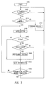
- step SP1 the system control circuit 9 proceeds from step SP1 to step SP2, and judges whether or not a command has been inputted from the host computer.
- step SP2 If a negative result is obtained here, the system control circuit 9 repeats this step SP2. If an affirmative result is obtained, it proceeds to step SP3 to judge whether or not that command is a command for setting the vendor ID.
- an unique ID code is set at an application program for reproducing the data which is stored in the optical disc 2. Moreover, the optical disc 2 sets this unique ID code to vendor ID and records this vendor ID in the vendor unique area of each sector.
- the application program which retrieves the data stored in this optical disc 2 issues the ID setting commands to set the ID data which is corresponding to this vendor ID.
- this ID data is stored in a memory (not shown) in the system control circuit 9.
- the system control circuit 9 judges whether or not the code issued from the host computer is ID setting commands. If a negative result is obtained at step SP3, it proceeds to step SP4 to judge whether or not the command is the read command.
- step SP4 If a negative result is obtained at step SP4, it proceeds to step SP5 to perform the command processing which is corresponding to the control command, and then returns to step SP2.
- the command processing represents the processing other than the ID setting command and the read command at special mode, which is, for example, the processing for write command, request sense command to examine an error status, and so on.
- step SP3 if an affirmative result is obtained at step SP3, it proceeds to step SP6 to set the operation mode to the special mode, and then analyzes the ID code which has been added to the ID setting command, to set the comparing ID.
- the comparing ID is set based on the ID code which is set at the application program supplied from the host computer.
- step SP4 the affirmative result is obtained at step SP4, and it proceeds to step SP7.
- the system control circuit 9 judges whether or not the current operation mode is the special mode. If the negative result is obtained, it proceeds to step SP5 to reproduce the user data which is assigned by the read command, and then returns to step SP2.
- step SP8 reproduce the sector which is assigned by the read command.
- step SP9 the error correction process of thus reproduced vendor unique area data is performed to detect the vendor ID, and then, by performing the specified logical operation process between the vendor ID and the comparing ID, it judges whether or not the vendor ID coincides with the comparing ID.
- step SP10 when the reproduced vendor ID coincides with the comparing ID, this means the case where the read command of this optical disc has been issued by the application program corresponding to the optical disc 2. Therefore, it proceeds to step SP10 to output the reproduced user data to the host computer.
- step SP9 If the negative result is obtained at step SP9, it proceeds to step SP11 to generate the data representing that an error has occurred, and then proceeds to step SP2. Therefore, the process which is corresponding to the read command is terminated, without outputting of the reproduced user data to the host computer.
- the optical disc device 1 only when the read command has been issued from the corresponding application program to the optical disc 2, the user data can be outputted. Thereby, the illegal copy can be inhibited. Besides, as to the optical disc 2 which is illegally copied, an illegal copying of it can be effectively avoided because the reproduced data is not outputted to the outside of the optical disc device 1.
- the data recorded in the vendor unique is controlled only in the optical disc device 1, and is not accessible from the outside of the optical disc device 1. Therefore, even if the user data is copied by some methods, the data of the vendor unique is not copied. The copy seems to be completed normally. However, if the copied user data is tried to be reproduced from the optical disc, the reproduced user data is not outputted to the outside of the optical disc device 1, that is the host computer, since the vendor unique are not coincident. Therefore, an illegal copy can be avoided.
- a logical sector of the optical disc 2 is regenerated based on the vendor ID which is allocated to the vendor unique, so that the illegal copy is effectively avoided.
- the head sector, the directory data, the file allocation table (FAT), etc. are recorded in the optical disc 2, and the file of the application loader is sequentially recorded in the optical disc 2.
- the directory data, the file allocation table (FAT), and the subsequent file of the application program are recorded in the optical disc 2.
- the operating system (OS) of the host computer issues the command of the reproduction from the logical sector "0" to the drive, so that the directory data and the file allocation table which have been place on the head sector are accessed, and the succeeding application loader is loaded to the host computer.
- OS operating system
- the position of the logical sector "0" is detected by accessing the management data (DDS: Disc Definition Structure) recorded in the innermost periphery of the optical disc 2, etc..
- DDS Disc Definition Structure
- the processing of the application program starts, based on the application loader which has been loaded into the host computer.
- the procedure shown in Fig. 6 is performed in response to the command which is issued by this application loader.
- step SP21 it proceeds from step SP21 to step SP22 to judge whether or not the command has been inputted from the host computer.
- step SP22 If a negative result is obtained, it repeats this step SP22. If an affirmative result is obtained, it proceeds to step SP23 to judge whether or not it is a logical sector search command.
- step SP24 the system control circuit 9 proceeds to step SP24 to perform the processing which is corresponding to the control command, and then returns to step SP22.
- the system control circuit 9 proceeds to the following step SP25 to set the target sector (TS) to the logical sector "0" written in DDS, and then proceeds to step SP26 to reproduce the sector of this logical sector "0".
- the system control circuit 9 take the data of the vendor unique out of the reproduced result.
- the data of the vendor unique is processed only in the drive, and the content of this data can not be accessed externally.
- the data of the predetermined value X is recorded into the vendor unique area of sector which is reset to the logical sector "0" on the optical disc 2, and the vendor ID of the value other than X is recorded for the residual sectors.
- the system control circuit 9 takes the data of the vendor unique from the sector of the logical sector "0", and then proceeds to step SP27 to judge that whether or not the vendor ID obtained from the data of the taken vendor unique is the predetermined value X. If the negative result is obtained, it proceeds to step SP28.
- step SP28 the system control circuit 9 increments the value of the target sector TS by one, and then proceeds to step SP29 to judge whether or not the target sector TS is the last sector.
- step SP26 If the negative result is obtained, it returns to step SP26 to reproduce the following sector.
- the system control circuit 9 thus repeats the procedure of steps SP26 - SP27 - SP28 - SP29 - SP26 sequentially, and if the vendor ID of the value X is detected, it proceeds to step SP30.
- the system control circuit 9 resets the sector where the vendor ID of the value X is detected to the sector of the logical sector "0", and returns to step SP22.
- the system control circuit 9 reproduces and outputs the directory data and the file allocation table based on the logical sector which has been reset, and further reproduces and outputs the following application program.
- an operation system of the host computer side is able to operate, independently of this resetting of the logical sector, in the same manner as the case where an application program is executed with respect to an usual optical disc.
- step SP31 the system control circuit 9 proceeds to step SP31.
- system control circuit 9 generates the data representing that an error has occurred, and then returns to step SP22.
- the vendor ID of the value X can not be detected for the reason that the copying of the vendor unique is impossible. Therefore, it is difficult to start-up this application program normally.
- the logical operation is performed and the judgment upon whether or not the vendor ID coincides with the comparing ID is formed.
- this invention is not only limited to this but the various logical operations may be performed between the vendor ID and the comparing ID, and the judgment upon whether or not the predetermined results of the operations are obtained is formed.
- the data of the vendor unique is referred to determine the type of user data, and the important data is processed to change if necessary.
- step SP41 it proceeds from step SP41 to step SP42 to judge that whether or not the command is inputted from the host computer.
- step SP42 If a negative result is obtained, it repeats step SP42. On the contrary, if an affirmative result is obtained, it proceeds to step SP43 judge that whether or not the inputted command is the read command.
- step SP44 the processing corresponding to the control command is performed, and then it returns to step SP42.
- step SP45 to reproduce the sector specified by the host computer.
- step SP46 the system control circuit 9 proceeds to step SP46 to detect the data of the vendor unique of the reproduced sector, and the specific logical calculation processing is performed between the data of this vendor unique and the predetermined value A to judge that whether or not the data of this vendor unique is the predetermined value A.
- the important data such like DDS is recorded more than two places on an optical disc.
- the predetermined value A is recorded in the data of the vendor unique of the important data such like DDS.
- the important data can be also recorded more than two places the same as the conventional device.
- step SP46 when the data of the vendor unique is the predetermined value A, it proceeds to step SP47.
- the error detecting and correcting circuit 11 obtains the information representing that how many errors are there at error correcting processing, and then supplies this information to the system control circuit 9.
- the system control circuit 9 judges that whether or not the error number per sector is over the reference value N, and if an affirmative result is obtained, it proceeds to step SP8 to perform the replacement processing.
- the replacement processing is to record the error corrected data from the vendor unique in the change sector formed at the other position on the optical disc.
- this reference value N is set lower than the reference value that the replacement processing is performed on the normal data such as the user data. Therefore, the important data such as DDS is surely change processed.
- bit error under 40 bytes per sector can be corrected regarding the burst type bit error, and further the bit error under 8 bytes can be corrected regarding the bit error of one column data (in Fig. 2, which is composed of sequential column data in vertical direction, D0, D5, ... D511).
- the host computer can surely access this type of important data so as to access a mass of file recorded on the optical disc 2.
- the system control circuit 9 performs the replacement processing, and proceeds to step SP49 to output the data of the reproduction sector stored in the buffer memory 13 to the host computer.
- step SP46 if a negative result is obtained at step SP46, it proceeds to step SP49 to output the data of the reproduction sector stored in the buffer memory 13 to the host computer, and then it proceeds to step SP50.
- the reproduced data is stored in the buffer memory 13 to output to the host computer
- the data in the directory which is frequently accessed on the basis of the data of the vendor unique is stored and held in the predetermined area of the different buffer memory 13 from the general user data. If the command to access this data is issued from the host computer, the data stored in the buffer memory 13 is outputted to the host computer without accessing the optical disc 2.
- the data in the directory which is frequently accessed on the basis of the data of the vendor unique uses the buffer 13 as the cash memory.
- the transmission time can be shorten to shorten the access time.
- step SP50 the data is transmitted to the host computer, and it proceeds to step SP50 to judge that whether or not the user data is transmitted for the sector number specified by the host computer.
- step SP50 if a negative result is obtained, it returns to step SP45 to reproduce the next sector. If an affirmative result is obtained, it returns to step SP42 to wait the input of next command.
- the important user data is change processed at the time when the error number is fewer than the general user data on the basis of the data of the vendor unique, so that the important data can be held to be reproducible at all times. Also, the cashing is performed on the user data which is accessed frequently on the basis of the data of the vendor unique, so as to shorten the access time.
- the above DDS is recorded at the innermost and outermost sector of the optical disc 2.
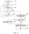
- the procedure shown in Fig. 8 is performed when the power turns on, resetting, or loading the optical disc 2, so that the DDS is retrieved on the basis of the data of the vendor unique.
- step SP51 when the power turns on, resetting is operated, or the optical disc 2 is loaded, the system control circuit 9 proceeds from step SP51 to step SP52 to set the logical sector of the target sector representing the object to be reproduced to the value "0".
- step SP53 the system control circuit 9 proceeds to step SP53 to reproduce the target sector of this logical sector "0", thereafter, the predetermined calculation processing is performed on the data VID of the vendor unique of the reproduced sector, and then it is judged that whether or not this data VID is the predetermined value C.
- the optical disc 2 set the data VID of the vendor unique to the predetermined value C, regarding the sector in which the construction data is recorded, so as to easily identify as the other user data.
- step SP54 If a negative result is obtained at step SP54, the system control circuit 9 proceeds to step SP55 to increment the logical sector of the target sector by value "1", and then returns to step SP53.
- the system control circuit 9 repeats the procedure of steps SP53 - SP54 - SP55 - SP53, so as to reproduce the sector of the optical disc 2 sequentially from the logical sector "0" and retrieve the sector in which the construction data is recorded.
- step SP54 After the sector in which the construction data is recorded is reproduced, if the affirmative result is obtained at step SP54, it proceeds to step SP56 to set the parameter for detecting the change sector, etc., based on the construction data (that is, the information of DDS) recorded in this sector.
- the optical disc 2 is accessed based on the set parameter, so that the desired user data can be recorded in the optical disc 2 and the data recorded in the optical disc 2 can be also reproduced.
- step SP57 the system control circuit 9 proceeds to step SP57 to judge that whether or not the number of errors at the reproduction of the construction data is over the predetermined value N, on the basis of the processing result of the error detecting and correcting circuit 11.
- step SP57 the system control circuit 9 proceeds to step SP58 to perform the replacement processing on the sector in which the construction data is recorded, and then it proceeds to step SP59. If a negative result is obtained, it proceeds to step SP59 directly.
- the system control circuit 9 outputs the control code to the buffer control circuit 10, etc., and re-records the construction data stored in the buffer memory 13 just after reproduction to the replacement sector of the optical disc 2.
- the replacement processing is performed and the construction data is held to the state that is surely reproducible.
- step SP59 to change the state to the state that the command to be inputted from the host computer is waited, thereafter, it proceeds to step SP60 to terminate this procedure.
- the construction data can be identified on the basis of the data of the vendor unique, and the replacement processing is performed, if necessary, to hold this construction data to be reproducible surely. Therefore, the reliability of the optical disc device can be improved.
Landscapes
- Engineering & Computer Science (AREA)
- Signal Processing (AREA)
- Computer Security & Cryptography (AREA)
- Multimedia (AREA)
- Physics & Mathematics (AREA)
- Optics & Photonics (AREA)
- Signal Processing For Digital Recording And Reproducing (AREA)
- Optical Recording Or Reproduction (AREA)
- Storage Device Security (AREA)
Applications Claiming Priority (4)
| Application Number | Priority Date | Filing Date | Title |
|---|---|---|---|
| JP22524693A JP3436393B2 (ja) | 1993-08-17 | 1993-08-17 | 光デイスク再生方法及び光デイスク |
| JP225246/93 | 1993-08-17 | ||
| JP238940/93 | 1993-08-31 | ||
| JP23894093A JPH0773606A (ja) | 1993-08-31 | 1993-08-31 | 光デイスク装置 |
Publications (2)
| Publication Number | Publication Date |
|---|---|
| EP0640924A2 true EP0640924A2 (de) | 1995-03-01 |
| EP0640924A3 EP0640924A3 (de) | 1997-04-23 |
Family
ID=26526524
Family Applications (1)
| Application Number | Title | Priority Date | Filing Date |
|---|---|---|---|
| EP94112775A Withdrawn EP0640924A3 (de) | 1993-08-17 | 1994-08-16 | Vorrichtung zur Wiedergabe von Daten. |
Country Status (3)
| Country | Link |
|---|---|
| US (3) | US5592454A (de) |
| EP (1) | EP0640924A3 (de) |
| KR (1) | KR100345970B1 (de) |
Cited By (2)
| Publication number | Priority date | Publication date | Assignee | Title |
|---|---|---|---|---|
| EP1024417A1 (de) * | 1995-07-28 | 2000-08-02 | Sony Corporation | Steuerung einer elektronischen Anlage |
| NL1014830C2 (nl) * | 1999-04-29 | 2001-01-24 | Hewlett Packard Co | Werkwijze voor het volgen van inrichtingen gebruikt voor het laden, lezen en beschrijven van verwijderbare opslagmedia. |
Families Citing this family (40)
| Publication number | Priority date | Publication date | Assignee | Title |
|---|---|---|---|---|
| US6121048A (en) * | 1994-10-18 | 2000-09-19 | Zaffaroni; Alejandro C. | Method of conducting a plurality of reactions |
| US6215758B1 (en) | 1996-10-04 | 2001-04-10 | Sony Corporation | Recording medium |
| US6011772A (en) * | 1996-09-16 | 2000-01-04 | Spectradisc Corporation | Machine-readable optical disc with reading-inhibit agent |
| US6747930B1 (en) | 1996-12-24 | 2004-06-08 | Hide & Seek Technologies, Inc. | Data protection on an optical disk |
| US6385257B1 (en) * | 1997-01-21 | 2002-05-07 | Sony Corporation | Frequency demodulating circuit, optical disk apparatus thereof and preformating device |
| US6310851B1 (en) | 1997-01-21 | 2001-10-30 | Sony Corporation | Frequency demodulating circuit, optical disk apparatus thereof and preformating device |
| TW388867B (en) * | 1997-05-21 | 2000-05-01 | Sony Corp | Transmission cable, jack to which transmission cable is inserted, and recording device |
| US6646967B1 (en) * | 1997-08-12 | 2003-11-11 | Denon Digital Llc | Method for making copy protected optical discs |
| EP0901122B1 (de) * | 1997-09-05 | 2006-06-14 | Pioneer Electronic Corporation | Informationserzeugungs- und -wiedergabeverfahren und -gerät sowie Informationsaufzeichnungsmedium |
| US6792538B1 (en) | 1997-09-05 | 2004-09-14 | Pioneer Electronic Corporation | Information generating method and apparatus, information reproducing method and apparatus, and information record medium |
| JP3488603B2 (ja) * | 1997-09-16 | 2004-01-19 | 株式会社東芝 | 電子透かしを利用したコピープロテクトシステム |
| KR100515719B1 (ko) * | 1998-02-20 | 2005-11-25 | 삼성전자주식회사 | 서보트랙라이터를 이용한 공정 관리 방법 |
| US6338933B1 (en) | 1998-06-25 | 2002-01-15 | Spectradisc Corporation | Methods and apparatus for rendering an optically encoded medium unreadable |
| US6531262B1 (en) | 1998-06-25 | 2003-03-11 | Spectradisc Corporation | Methods and apparatus for rendering an optically encoded medium unreadable and tamper-resistant |
| JP2000251419A (ja) * | 1999-02-26 | 2000-09-14 | Sony Corp | 読み出し制御装置、再生装置、記録装置およびその方法 |
| AU777945B2 (en) * | 1999-07-12 | 2004-11-04 | Flexplay Technologies, Inc. | Disposable optical storage media and manufacturing method |
| BR0006922A (pt) * | 1999-07-13 | 2001-07-31 | Koninkl Philips Electronics Nv | Dispositivo para varrer um portador de informação, processo de fabricação de um portador de informação, e, portador de informação portando informação de identificação |
| KR100337179B1 (ko) * | 2000-03-10 | 2002-05-18 | 이중학 | 광디스크 복사 사용 방지 장치 및 방법 |
| US7486790B1 (en) | 2000-06-30 | 2009-02-03 | Verification Technologies, Inc. | Method and apparatus for controlling access to storage media |
| US20050063256A1 (en) * | 2000-06-30 | 2005-03-24 | Selinfreund Richard H. | Data storage in optical discs |
| US6638593B2 (en) | 2000-06-30 | 2003-10-28 | Verification Technologies, Inc. | Copy-protected optical media and method of manufacture thereof |
| US7124944B2 (en) * | 2000-06-30 | 2006-10-24 | Verification Technologies, Inc. | Product packaging including digital data |
| WO2002002301A1 (en) | 2000-06-30 | 2002-01-10 | Verification Technologies Inc. | Copy-protected optical media and method of manufacture thereof |
| US7660415B2 (en) * | 2000-08-03 | 2010-02-09 | Selinfreund Richard H | Method and apparatus for controlling access to storage media |
| US6477124B2 (en) * | 2000-11-15 | 2002-11-05 | Doug Carson & Associates, Inc. | Varying the rate at which data appear on an optical disc rotated at a constant linear velocity to prevent unauthorized duplication of the disc |
| US7568081B2 (en) * | 2000-11-15 | 2009-07-28 | Doug Carson & Associates, Inc. | Authenticating a data storage medium using predetermined inter-sector relationships |
| US6982109B2 (en) * | 2000-12-11 | 2006-01-03 | Flexplay Technologies, Inc. | Method for rendering surface layer of limited play disk lightfast |
| WO2002099470A2 (en) * | 2001-06-05 | 2002-12-12 | Flexplay Technologies, Inc. | Limited play optical devices with interstitial reactive layer and methods of making same |
| US20050084645A1 (en) * | 2002-02-07 | 2005-04-21 | Selinfreund Richard H. | Method and system for optical disc copy-protection |
| US7102973B1 (en) | 2002-04-12 | 2006-09-05 | Dc Ip, Llc | Media authentication using altered sector sizes |
| KR100505640B1 (ko) * | 2002-09-09 | 2005-08-03 | 삼성전자주식회사 | 디스크 구동기에 있어서 최적의 기록 파워 결정 장치 및방법 |
| MXPA05003218A (es) * | 2002-09-26 | 2005-09-12 | Verification Technologies Inc | Autentificacion de items que utilizan materiales de cambio transitorio de estado optico. |
| US20060203700A1 (en) * | 2003-02-06 | 2006-09-14 | Verification Technologies, Inc. | Method and system for optical disk copy-protection |
| DE102004046618A1 (de) * | 2004-09-25 | 2006-03-30 | Robert Bosch Gmbh | Schaltungsanordnung zum Analog/Digital-Wandeln |
| US7577809B2 (en) * | 2005-11-02 | 2009-08-18 | Promethean Storage Llc | Content control systems and methods |
| KR100696845B1 (ko) * | 2005-12-19 | 2007-03-19 | 주식회사 대우일렉트로닉스 | 광디스크 녹화 시스템의 광디스크 튜닝값 검출 방법 |
| US7571368B1 (en) * | 2006-01-26 | 2009-08-04 | Promethean Storage Llc | Digital content protection systems and methods |
| US7509441B1 (en) * | 2006-06-30 | 2009-03-24 | Siliconsystems, Inc. | Systems and methods for segmenting and protecting a storage subsystem |
| US8549236B2 (en) * | 2006-12-15 | 2013-10-01 | Siliconsystems, Inc. | Storage subsystem with multiple non-volatile memory arrays to protect against data losses |
| US7774560B2 (en) * | 2007-11-30 | 2010-08-10 | Aten International Co., Ltd. | Storage emulator and method thereof |
Family Cites Families (14)
| Publication number | Priority date | Publication date | Assignee | Title |
|---|---|---|---|---|
| FR2528196B1 (fr) * | 1982-06-07 | 1988-05-27 | Fortune Systems Corp | Appareil de protection de programmes d'ordinateur |
| JPS62102482A (ja) * | 1985-10-28 | 1987-05-12 | Matsushita Electric Ind Co Ltd | 情報記録再生装置 |
| JPS636628A (ja) * | 1986-06-27 | 1988-01-12 | Hitachi Ltd | 情報記録制御方式 |
| JPH0754613B2 (ja) * | 1986-07-21 | 1995-06-07 | 松下電器産業株式会社 | 光デイスクのコピ−防止方法 |
| US4814903A (en) * | 1987-06-29 | 1989-03-21 | International Business Machines Corporation | Alternate storage areas in magnetooptical media |
| US4866769A (en) * | 1987-08-05 | 1989-09-12 | Ibm Corporation | Hardware assist for protecting PC software |
| US4939598A (en) * | 1988-02-08 | 1990-07-03 | International Business Machines Corporation | Managing data storage space on large capacity record media |
| JPH02293930A (ja) * | 1989-05-08 | 1990-12-05 | Victor Co Of Japan Ltd | 記録媒体の記録内容の盗用防止方式 |
| JP3273781B2 (ja) * | 1989-09-21 | 2002-04-15 | コーニンクレッカ フィリップス エレクトロニクス エヌ ヴイ | 記録担体及び記録担体を得る方法及び装置及び複写防止手段を持つ情報記録装置 |
| DE4021535A1 (de) * | 1990-07-06 | 1992-01-16 | Gigatape Systeme Fuer Datensic | Verfahren zum erzeugen eines individuellen datentraegerschutzes gegen eine unautorisierte benutzung |
| JPH04274058A (ja) * | 1991-02-28 | 1992-09-30 | Olympus Optical Co Ltd | 情報記録再生装置 |
| US5418852A (en) * | 1992-03-18 | 1995-05-23 | Fujitsu Limited | Unauthorized use prevention method for optical disks, optical disk having unauthorized use prevention function, and optical disk apparatus |
| JP2751733B2 (ja) * | 1992-05-27 | 1998-05-18 | 日本電気株式会社 | フロッピィ・ディスク装置用データフォーマット制御コントローラ |
| JPH064884A (ja) * | 1992-06-17 | 1994-01-14 | Canon Inc | 情報記録再生装置 |
-
1994
- 1994-08-16 EP EP94112775A patent/EP0640924A3/de not_active Withdrawn
- 1994-08-17 KR KR1019940020199A patent/KR100345970B1/ko not_active Expired - Fee Related
-
1995
- 1995-10-06 US US08/540,313 patent/US5592454A/en not_active Expired - Lifetime
- 1995-10-06 US US08/540,222 patent/US5721873A/en not_active Expired - Fee Related
-
1996
- 1996-06-13 US US08/661,304 patent/US5812512A/en not_active Expired - Fee Related
Cited By (5)
| Publication number | Priority date | Publication date | Assignee | Title |
|---|---|---|---|---|
| EP1024417A1 (de) * | 1995-07-28 | 2000-08-02 | Sony Corporation | Steuerung einer elektronischen Anlage |
| US6247132B1 (en) | 1995-07-28 | 2001-06-12 | Sony Corporation | Electronic equipment, method of controlling operation thereof and controlling method |
| US6381697B1 (en) | 1995-07-28 | 2002-04-30 | Sony Corporation | Electronic equipment, method of controlling operation thereof and controlling method |
| NL1014830C2 (nl) * | 1999-04-29 | 2001-01-24 | Hewlett Packard Co | Werkwijze voor het volgen van inrichtingen gebruikt voor het laden, lezen en beschrijven van verwijderbare opslagmedia. |
| US6625732B1 (en) | 1999-04-29 | 2003-09-23 | Charles R Weirauch | Method for tracking the devices used to load, read, and write removable storage media |
Also Published As
| Publication number | Publication date |
|---|---|
| US5721873A (en) | 1998-02-24 |
| US5592454A (en) | 1997-01-07 |
| KR950006750A (ko) | 1995-03-21 |
| KR100345970B1 (ko) | 2002-12-06 |
| US5812512A (en) | 1998-09-22 |
| EP0640924A3 (de) | 1997-04-23 |
Similar Documents
| Publication | Publication Date | Title |
|---|---|---|
| US5592454A (en) | Data reproducing apparatus which replaces vendor unique identification data in response to a reference error correction rate which is lower than that used for replacement of other data | |
| RU2204175C2 (ru) | Носитель записи для запоминания информации о типе связывания и способ обработки поврежденной области с использованием этой информации | |
| US5978336A (en) | Optical disk finalization method and optical disk finalization apparatus | |
| JP2776006B2 (ja) | 情報記録再生装置 | |
| US5265230A (en) | Method and apparatus for determining sector status in a data storage device by writing a status of read-only, writable, or obliterated in an error recovery area of each sector | |
| CN100452228C (zh) | 用于信息记录介质的信息记录与再现方法和装置 | |
| JP2002015507A (ja) | データ記録方法およびディスク装置 | |
| EP1550123A1 (de) | Dichtes, einmal beschreibbares aufzeichnungsmedium, dass defektverwaltung erlaubt; und verfahren und vorrichtung zur verwaltung von defekten | |
| JPH02216672A (ja) | 光ディスクドライブ装置 | |
| US20060039246A1 (en) | Adaptive system to allow multiple update and correction sessions on an optical data storage card | |
| RU2343567C2 (ru) | Носитель записи информации, устройство записи/воспроизведения и способ записи/воспроизведения | |
| EP0490400B1 (de) | Gerät zum Speichern von Information | |
| TW200531024A (en) | Device and method for recording information | |
| US7583575B2 (en) | Method of managing defects for a write-once recording medium, reproducing and/or recording apparatus implementing the same, a corresponding write-once recording medium therefor, and medium including computer readable code controlling the implementation of the same | |
| US5522035A (en) | Buffer memory self-diagnosis method for information signal processing apparatus | |
| JP2007511033A (ja) | 情報記録媒体、記録/再生方法及び記録/再生装置 | |
| US6983292B1 (en) | Method and apparatus for formatting and initialization of re-writable optical media | |
| JPH04245072A (ja) | 媒体上にデ−タ管理情報領域を備えたディスク装置 | |
| JP2000040306A (ja) | 書換可能な記録膜を用いた追記型光ディスク、および光ディスク初期化方法および光ディスク再生方法および光ディスク追記方法、および光ディスク初期化装置および光ディスク再生装置および光ディスク追記装置 | |
| US6782493B2 (en) | Method of verifying defect management area information of optical disc upon initialization without certification and test apparatus for performing the same | |
| JP3264528B2 (ja) | ライトプロテクトされた情報記録媒体の情報交替処理方法 | |
| JPH0757375A (ja) | 光デイスク装置 | |
| JP4015544B2 (ja) | 情報処理装置 | |
| JP3892729B2 (ja) | プログラム及び記録媒体 | |
| US20070070857A1 (en) | Method and apparatus for accessing an optical storage medium |
Legal Events
| Date | Code | Title | Description |
|---|---|---|---|
| PUAI | Public reference made under article 153(3) epc to a published international application that has entered the european phase |
Free format text: ORIGINAL CODE: 0009012 |
|
| AK | Designated contracting states |
Kind code of ref document: A2 Designated state(s): DE FR GB |
|
| PUAL | Search report despatched |
Free format text: ORIGINAL CODE: 0009013 |
|
| AK | Designated contracting states |
Kind code of ref document: A3 Designated state(s): DE FR GB |
|
| 17P | Request for examination filed |
Effective date: 19970924 |
|
| 17Q | First examination report despatched |
Effective date: 19980806 |
|
| STAA | Information on the status of an ep patent application or granted ep patent |
Free format text: STATUS: THE APPLICATION IS DEEMED TO BE WITHDRAWN |
|
| 18D | Application deemed to be withdrawn |
Effective date: 20070301 |