EP0641003B1 - Elektromagnetisches Relais mit bistabilem Kontakt - Google Patents
Elektromagnetisches Relais mit bistabilem Kontakt Download PDFInfo
- Publication number
- EP0641003B1 EP0641003B1 EP19940410057 EP94410057A EP0641003B1 EP 0641003 B1 EP0641003 B1 EP 0641003B1 EP 19940410057 EP19940410057 EP 19940410057 EP 94410057 A EP94410057 A EP 94410057A EP 0641003 B1 EP0641003 B1 EP 0641003B1
- Authority
- EP
- European Patent Office
- Prior art keywords
- blade
- electromagnetic relay
- rocker
- relay according
- spring
- Prior art date
- Legal status (The legal status is an assumption and is not a legal conclusion. Google has not performed a legal analysis and makes no representation as to the accuracy of the status listed.)
- Expired - Lifetime
Links
Images

Classifications
-
- H—ELECTRICITY
- H01—ELECTRIC ELEMENTS
- H01H—ELECTRIC SWITCHES; RELAYS; SELECTORS; EMERGENCY PROTECTIVE DEVICES
- H01H50/00—Details of electromagnetic relays
- H01H50/64—Driving arrangements between movable part of magnetic circuit and contact
-
- H—ELECTRICITY
- H01—ELECTRIC ELEMENTS
- H01H—ELECTRIC SWITCHES; RELAYS; SELECTORS; EMERGENCY PROTECTIVE DEVICES
- H01H50/00—Details of electromagnetic relays
- H01H50/08—Indicators; Distinguishing marks
Definitions
- the object of the invention is to provide a device operated by a contact tiltable bistable, and easily configurable as an electromagnetic relay from of a standard structure of a remote control switch.
- control member comprises an articulated connecting rod on the pallet and the pendulum to form a permanent direct link, the point of articulation of the rod on the balance being offset relative to the axis of tilting.
- the elastic return device comprises a pair of compression springs acting on the underside of the pallet, and extending parallel to each other and to the rod in a direction substantially perpendicular to the pallet, the two springs having characteristics of different length and stiffness, one of the springs acting before the other.
- a contact position indicator is integrated inside the manually operated test button.
- the indicator is composed of an optical prism cooperating with a probe integral with the pallet, the probe having two signaling marks arranged alternately opposite the inclined face of the prism according to the position drawn or moved away from the pallet.
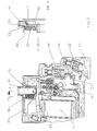
- FIG. 1 is an elevation view of the electromagnetic relay according to the invention, shown in the OFF position when the electromagnet is not supplied.
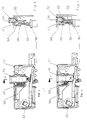
- Figure 2 is an identical view to Figure 1, the relay being equipped with a device additional with test button and contact position indicator.
- Figure 3 is a sectional view along line 3-3 of Figure 2.
- Figure 4 shows a partial view of Figure 2, showing the indicator in ON position of the relay following energization of the electromagnet.
- Figure 5 is a sectional view along line 5-5 of Figure 4.
- Figure 6 shows a partial view of Figure 2, after pressing the button test.
- Figure 7 is a sectional view along line 7-7 of Figure 6.
- the changeover relay 10 is housed in a housing 12 in molded insulating material containing an electromagnet 14, a control mechanism 16, and an electrical power circuit 18 having a movable contact 20 tilting cooperating with two fixed contacts 22, 24.
- the fixed contact 22 is connected to a first terminal 26, and the other fixed contact 24 of the change-over relay 10 is connected to a second terminal 28, the two terminals 26, 28 being located on the same side of the case 12.
- the movable contact 20 is equipped with a contact arm 30 pivotally mounted on a articulation 32 with knife, arranged at the end of a rigid conductor 34, of which the other end is connected to a third terminal 36.
- the contact arm 30 is associated with a spring 38 in the form of an elastic blade making the movable contact 20 bistable.
- the third terminal 36 is located opposite the other two terminals 26, 28.
- the electromagnet 14 comprises a ferromagnetic pallet 38 pivotally mounted on the left side of the cylinder head 40, and a biasing spring 42 cooperates with the pallet 38 in the vicinity of the articulation zone 43 to ensure minimum clearance during the pivoting movement.
- the control mechanism 16 comprises a balance 44 pivotally mounted on an axis 46 fixed between two extreme angular positions, and a connecting rod 48 articulated at one of its ends on the pallet 38, and at its other end on the balance 44.
- the articulation point 50 of the link 48 on the balance 44 is offset from the tilting axis 46.
- the pendulum 44 has a U-shape having a central recess 52 in which is engaged the end of the contact arm 30.
- the pallet 38 moves the pendulum 44 from one position to the other at each operation cycle of the pallet 38 depending on whether the electromagnet 14 goes from the excitation state to the rest state, or vice versa.
- the pallet 38 In the idle state of the electromagnet 14 corresponding to the absence of excitation of its coil, the pallet 38 is kept apart from the pole surface 54 of the cylinder head 40 thanks to an elastic return device 56 arranged between the housing 12 and a portion of the palette.
- the return device 56 comprises a pair of springs 58.60 compression bearing on protrusions 62 of the housing 12, and acting directly on the underside of the pallet 38 in the spacing direction.
- the movable contact 20, is in abutment against the upper fixed contact 24 in the position shown in Figure 1.
- the two springs 58, 60 extend parallel to each other in a direction perpendicular to the pallet 38.
- the pallet 38 When the electromagnet 14 is energized, the pallet 38 is attracted against the surface pole 54, and the link 48 causes the rocker 44 to tilt so as to drive the movable contact 20 to the fixed contact 22 lower.
- the modulation of the return force by the two springs 58, 60 allows an optimal accumulation of the excess energy supplied by the electromagnet 14 during the attraction of the pallet 38.
- the spring 58 on the left located between the articulation zone 43 of the pallet 38 and the other spring 60 on the right, is used to detach the contacts 20, 22 when the arm of contact 30 pivots anti-clockwise.
- Spring 58 le shorter has a higher hardness than the longer spring 60.
- the relaxation of first spring 58 on the left is used to break the micro-welds, while the other spring 60 on the right ensures the complete spacing of the pallet 38, and the tilting of the movable contact 20 towards the other stable state pressing against the contact fixed 24 upper.
- Figures 2 to 5 show the change-over relay 10 of Figure 1 additionally equipped a test button 70 in front of which an indicator 72 for the position of the contacts 20, 22; 20, 24.
- the manually operated test button 70 passes through an orifice 74 passage formed in the front face 76 of the housing 12, and is used to actuate mechanically the pallet 38 in the direction of approximation with the pole surface 54, so as to transmit a rocking movement to the balance 44, and from this changes the state of the moving contact 20 following each depression of the test button 70.
- an optical prism 78 cooperating with a position probe 80 integral with the pallet 38.
- the probe 80 carries a first colored marker 82 which moves in translation along the prism 78 while occupying two extreme positions depending on the location of the pallet 38.
- test button 70, the prism 78, the probe 80 and a return spring 86 are mounted in a support 88 secured to the housing 12.
- the support 88 carries a second color marker 84 different in color from the first marker 82.
- the contacts 20, 22 of the first series of contacts are open, and the other contacts 20, 24 of the second series are closed.
- the first benchmark 82 of the probe 80 is arranged opposite the inclined face of the prism 78, which reflects the coloring of the first marker 82 towards the head of the prism 78.
- test button 70 is not pressed, and permanently protrudes by the action of the return spring of the type compression 86.
- the manual depressing of the test button 70 in the orifice 74 causes the forced tilting of the rocker 44, and the change of state contacts.
- the signaling given by the indicator 72 is not correct, but remains invisible since the operator hides the prism head 78 as long as his finger pushes on the test button 70.
- indicator 72 and the test button 70 could be arranged differently without departing from the scope of the invention.
- a variant consists in particular of use an elongated prism and a probe with two different color markers. When the electromagnet is activated the indicator moves and shows its second color 92.
Landscapes
- Physics & Mathematics (AREA)
- Electromagnetism (AREA)
- Apparatuses For Generation Of Mechanical Vibrations (AREA)
- Length Measuring Devices With Unspecified Measuring Means (AREA)
- Testing Electric Properties And Detecting Electric Faults (AREA)
- Optical Couplings Of Light Guides (AREA)
- Measuring Leads Or Probes (AREA)
- Electromagnets (AREA)
Claims (7)
- Elektromagnetisches Relais in einem Isolierstoffgehäuse (12), dasdadurch gekennzeichnet, daßeinen Elektromagneten (14) mit ferromagnetischem Kippanker (38),einen Betätigungsmechanismus (16) mit einer, auf einer Achse (46) gelagerten, zwischen zwei Winkelendlagen verschwenkbaren Wippe (44),ein fest mit dem Anker (38) verbundenes und mit der Wippe (44) zusammenwirkendes Betätigungsorgan zur Überführung der Wippe von einer Stellung in die andere bei jedem Schaltspiel des Ankers (38),einen Leistungskreis (18) mit einem, durch die Wippe (44) betätigten und mit mindestens einem feststehenden Kontakt (22, 24) zusammenwirkenden bistabilen Kippkontakt (20)sowie eine Feder-Rückstellvorrichtung (56) zur Beaufschlagung des Ankers (38) in Richtung der Abzugstellung im Ruhezustand des Elektromagneten (14) enthält,
das Betätigungsorgan eine zur Bildung einer direkten, dauerhaften Verbindung an den Anker (38) und die Wippe (44) angelenkte Verbindungsstange (48) umfaßt, wobei der Gelenkpunkt (50) der Stange (48) auf der Wippe (44) leicht versetzt zur Schwenkachse (46) angeordnet ist. - Elektromagnetisches Relais nach Anspruch 1, dadurch gekennzeichnet, daß die Feder-Rückstellvorrichtung (56) zwei nacheinander auf die Unterseite des Ankers (38) wirkende, parallel zueinander und zur Stange (48) sowie annähernd senkrecht zum Anker (38) angeordnete Druckfedern (58, 60) umfaßt.
- Elektromagnetisches Relais nach Anspruch 1 oder 2, dadurch gekennzeichnet, daß an der Vorderseite des Gehäuses (12) eine Durchführungsöffnung (74) für eine Prüftaste (70) zur manuellen Betätigung der Wippe (44) ausgebildet und eine Kontaktstellungsanzeige (72) in die Prüftaste (70) integriert ist.
- Elektromagnetisches Relais nach Anspruch 3, dadurch gekennzeichnet, daß die Anzeige (72) aus einem optischen Prisma (78) besteht, das mit einem, am Anker (38) befestigten Positionsgeber (80) zusammenwirkt, wobei der Positionsgeber mindestens ein Schauzeichen (82, 92) aufweist, das in Abhängigkeit von der Anzugs- oder Abzugsstellung des Ankers (38) mit der schrägen Fläche des Prismas (78) zusammenwirken kann.
- Elektromagnetisches Relais nach Anspruch 3 oder 4, dadurch gekennzeichnet, daß die Anzeige (72) zwei Schauzeichen (82, 84) unterschiedlicher Farbgebung aufweist und das Prisma (78) so ausgebildet ist, daß es den Farbstrahl jedes Schauzeichens (82, 84) zur Vorderseite hin reflektiert.
- Elektromagnetisches Relais nach Anspruch 4 oder 5, dadurch gekennzeichnet, daß zwischen dem Anker (38) und der Vorderseite des Gehäuses (12) eine Feder (86) angeordnet ist, um die Prüftaste (70) in Richtung einer Vorsprung-Stellung zu beaufschlagen, die eine zuverlässige Funktionsweise der Anzeige (72) ermöglicht.
- Elektromagnetisches Relais nach Anspruch 2, dadurch gekennzeichnet, daß die zwischen der Stange (48) und der zweiten Feder (60) angeordnete erste, kürzere Feder (58) härter ist als die genannte zweite Feder.
Applications Claiming Priority (2)
| Application Number | Priority Date | Filing Date | Title |
|---|---|---|---|
| FR9310341A FR2709370B1 (fr) | 1993-08-26 | 1993-08-26 | Relais électromagnétique à contact bistable. |
| FR9310341 | 1993-08-26 |
Publications (2)
| Publication Number | Publication Date |
|---|---|
| EP0641003A1 EP0641003A1 (de) | 1995-03-01 |
| EP0641003B1 true EP0641003B1 (de) | 1998-12-23 |
Family
ID=9450438
Family Applications (1)
| Application Number | Title | Priority Date | Filing Date |
|---|---|---|---|
| EP19940410057 Expired - Lifetime EP0641003B1 (de) | 1993-08-26 | 1994-07-27 | Elektromagnetisches Relais mit bistabilem Kontakt |
Country Status (6)
| Country | Link |
|---|---|
| EP (1) | EP0641003B1 (de) |
| CN (1) | CN1037555C (de) |
| BR (1) | BR9403330A (de) |
| DE (1) | DE69415440T2 (de) |
| ES (1) | ES2126728T3 (de) |
| FR (1) | FR2709370B1 (de) |
Cited By (1)
| Publication number | Priority date | Publication date | Assignee | Title |
|---|---|---|---|---|
| WO2010139113A1 (zh) | 2009-06-03 | 2010-12-09 | Abb瑞士有限公司 | 模块化低压开关器 |
Families Citing this family (7)
| Publication number | Priority date | Publication date | Assignee | Title |
|---|---|---|---|---|
| DE29615689U1 (de) * | 1996-09-09 | 1996-10-31 | Siemens AG, 80333 München | Elektrisches Schaltgerät |
| DE19903751A1 (de) * | 1999-01-30 | 2000-08-24 | Eltako Gmbh Schaltgeraete | Elektromechanisches Schaltgerät |
| JP4168820B2 (ja) * | 2003-04-24 | 2008-10-22 | オムロン株式会社 | 電磁継電器 |
| SI23747A (sl) | 2011-05-12 | 2012-11-30 | ISKRA@MIS@@d@d | Bistabilno stikalo z bistabilnim mehanizmom |
| WO2014196934A1 (en) | 2013-06-06 | 2014-12-11 | NELA razvojni center d.o.o. | Bistable mechanism for switching electrical loads |
| DE102015110382A1 (de) * | 2015-06-29 | 2016-12-29 | Eaton Industries (Austria) Gmbh | Schaltgerät |
| US12061007B2 (en) * | 2020-02-07 | 2024-08-13 | Carrier Corporation | A2L compliant contactor |
Family Cites Families (4)
| Publication number | Priority date | Publication date | Assignee | Title |
|---|---|---|---|---|
| DE1085443B (de) * | 1959-04-25 | 1960-07-14 | Licentia Gmbh | Melderelais |
| FR2482773A1 (fr) * | 1980-05-16 | 1981-11-20 | Merlin Gerin | Telerupteur a boitier miniature |
| DE3736617A1 (de) * | 1987-10-29 | 1989-05-11 | Asea Brown Boveri | Einrichtung zur anzeige einer bestimmten stellung eines innerhalb eines gebaeudes beweglichen bauelementes |
| FR2676590B1 (fr) * | 1991-05-16 | 1994-06-17 | Merlin Gerin | Telerupteur a contact basculant. |
-
1993
- 1993-08-26 FR FR9310341A patent/FR2709370B1/fr not_active Expired - Fee Related
-
1994
- 1994-07-27 DE DE1994615440 patent/DE69415440T2/de not_active Expired - Fee Related
- 1994-07-27 ES ES94410057T patent/ES2126728T3/es not_active Expired - Lifetime
- 1994-07-27 EP EP19940410057 patent/EP0641003B1/de not_active Expired - Lifetime
- 1994-08-25 BR BR9403330A patent/BR9403330A/pt not_active IP Right Cessation
- 1994-08-25 CN CN 94115707 patent/CN1037555C/zh not_active Expired - Fee Related
Cited By (1)
| Publication number | Priority date | Publication date | Assignee | Title |
|---|---|---|---|---|
| WO2010139113A1 (zh) | 2009-06-03 | 2010-12-09 | Abb瑞士有限公司 | 模块化低压开关器 |
Also Published As
| Publication number | Publication date |
|---|---|
| ES2126728T3 (es) | 1999-04-01 |
| FR2709370B1 (fr) | 1995-10-20 |
| DE69415440T2 (de) | 1999-06-10 |
| EP0641003A1 (de) | 1995-03-01 |
| BR9403330A (pt) | 1995-04-11 |
| CN1104368A (zh) | 1995-06-28 |
| FR2709370A1 (fr) | 1995-03-03 |
| CN1037555C (zh) | 1998-02-25 |
| DE69415440D1 (de) | 1999-02-04 |
Similar Documents
| Publication | Publication Date | Title |
|---|---|---|
| CA1112271A (fr) | Contacteur electro-magnetique equipe d'un electro-aimant sensible aux surintensites pour provoquer la limitation et la coupure des courants excessifs | |
| EP0452230B1 (de) | Antriebsmechanismus für Schutzschalter | |
| EP0641003B1 (de) | Elektromagnetisches Relais mit bistabilem Kontakt | |
| EP0342133A1 (de) | Betätigungsmechanismus für Kleinschalter mit Anzeige einer Kontaktschweissung | |
| FR2697670A1 (fr) | Relais constituant un actionneur mécanique pour déclencher un disjoncteur ou un interrupteur différentiel. | |
| FR2777079A1 (fr) | Dispositif pour la detection de l'ouverture d'un compteur | |
| FR2516298A1 (fr) | Appareil contacteur comportant des moyens d'ouverture automatique et un organe de commande locale | |
| CA1203825A (fr) | Dispositif amovible de verrouillage d'un contacteur dans sa position de travail | |
| CH635911A5 (fr) | Valve pour fluide a commande manuelle. | |
| EP0271366B1 (de) | Ferngesteuerter Schalter mit einem Hilfsumschalter in dessen Ansteuerschaltung | |
| CA1304111C (fr) | Electro-aimant, notamment pour l'actionnement des interrupteurs d'un appareil contacteur | |
| EP0514296B1 (de) | Ferngesteuerter Schalter mit schwenkbarem Kontakt | |
| FR2645340A1 (fr) | Mecanisme de commande pour commutateur a la fermeture-ouverture | |
| EP0256901B1 (de) | Schaltvorrichtung mit symmetrischer Perkussion unter Verwendung eines Sprungwerkes mit Überschreitung eines Totpunktes | |
| EP0866483A1 (de) | Bistabiler Batterieschalter mit mechanischer Verrieglung | |
| EP0693764A1 (de) | Elektrischer Lastschalter mit elektromagnetischem Betätiger für Hochstrom | |
| BE1005375A0 (fr) | Dispositif d'enclenchement brusque d'un levier de contact monte de facon mobile, en particulier pour un commutateur de protection contre des courants de defaut. | |
| EP0246131B1 (de) | Elektrische, bistabile Schaltvorrichtung | |
| EP0905735B1 (de) | Schutzschalter mit elektromagnetischen Auslöser mit Antrieb für einen beweglichen und gabelförmigen Kontakt | |
| FR2722608A1 (fr) | Propulseur electromagnetique de disjoncteur basse tension | |
| EP0373018B1 (de) | Handbetätigter Mechanismus für schnelle Unterbrechung für elektrische Schalter | |
| FR2505194A1 (fr) | Dispositif destine a un appareil de jeu comprenant une bille et un champ de jeu en pente, notamment un billard electrique | |
| FR2632770A1 (fr) | Contacteur a quatre positions a effet tactile | |
| EP0926693A1 (de) | Selektiver Auslöser für Leistungsschalter | |
| EP0624892B1 (de) | Mit einem zeitverzögerten Abschaltsystem versehener ferngesteuerter Schalter |
Legal Events
| Date | Code | Title | Description |
|---|---|---|---|
| PUAI | Public reference made under article 153(3) epc to a published international application that has entered the european phase |
Free format text: ORIGINAL CODE: 0009012 |
|
| AK | Designated contracting states |
Kind code of ref document: A1 Designated state(s): BE DE ES GB IT |
|
| 17P | Request for examination filed |
Effective date: 19950710 |
|
| GRAG | Despatch of communication of intention to grant |
Free format text: ORIGINAL CODE: EPIDOS AGRA |
|
| 17Q | First examination report despatched |
Effective date: 19980313 |
|
| GRAG | Despatch of communication of intention to grant |
Free format text: ORIGINAL CODE: EPIDOS AGRA |
|
| GRAH | Despatch of communication of intention to grant a patent |
Free format text: ORIGINAL CODE: EPIDOS IGRA |
|
| GRAH | Despatch of communication of intention to grant a patent |
Free format text: ORIGINAL CODE: EPIDOS IGRA |
|
| GRAA | (expected) grant |
Free format text: ORIGINAL CODE: 0009210 |
|
| AK | Designated contracting states |
Kind code of ref document: B1 Designated state(s): BE DE ES GB IT |
|
| REF | Corresponds to: |
Ref document number: 69415440 Country of ref document: DE Date of ref document: 19990204 |
|
| GBT | Gb: translation of ep patent filed (gb section 77(6)(a)/1977) |
Effective date: 19990119 |
|
| ITF | It: translation for a ep patent filed | ||
| REG | Reference to a national code |
Ref country code: ES Ref legal event code: FG2A Ref document number: 2126728 Country of ref document: ES Kind code of ref document: T3 |
|
| PGFP | Annual fee paid to national office [announced via postgrant information from national office to epo] |
Ref country code: DE Payment date: 19990708 Year of fee payment: 6 |
|
| PGFP | Annual fee paid to national office [announced via postgrant information from national office to epo] |
Ref country code: ES Payment date: 19990719 Year of fee payment: 6 |
|
| PGFP | Annual fee paid to national office [announced via postgrant information from national office to epo] |
Ref country code: GB Payment date: 19990721 Year of fee payment: 6 |
|
| PGFP | Annual fee paid to national office [announced via postgrant information from national office to epo] |
Ref country code: BE Payment date: 19990915 Year of fee payment: 6 |
|
| PLBE | No opposition filed within time limit |
Free format text: ORIGINAL CODE: 0009261 |
|
| STAA | Information on the status of an ep patent application or granted ep patent |
Free format text: STATUS: NO OPPOSITION FILED WITHIN TIME LIMIT |
|
| 26N | No opposition filed | ||
| PG25 | Lapsed in a contracting state [announced via postgrant information from national office to epo] |
Ref country code: GB Free format text: LAPSE BECAUSE OF NON-PAYMENT OF DUE FEES Effective date: 20000727 |
|
| PG25 | Lapsed in a contracting state [announced via postgrant information from national office to epo] |
Ref country code: ES Free format text: LAPSE BECAUSE OF NON-PAYMENT OF DUE FEES Effective date: 20000728 |
|
| PG25 | Lapsed in a contracting state [announced via postgrant information from national office to epo] |
Ref country code: BE Free format text: LAPSE BECAUSE OF NON-PAYMENT OF DUE FEES Effective date: 20000731 |
|
| BERE | Be: lapsed |
Owner name: S.A. SCHNEIDER ELECTRIC Effective date: 20000731 |
|
| GBPC | Gb: european patent ceased through non-payment of renewal fee |
Effective date: 20000727 |
|
| PG25 | Lapsed in a contracting state [announced via postgrant information from national office to epo] |
Ref country code: DE Free format text: LAPSE BECAUSE OF NON-PAYMENT OF DUE FEES Effective date: 20010501 |
|
| REG | Reference to a national code |
Ref country code: ES Ref legal event code: FD2A Effective date: 20020603 |
|
| PG25 | Lapsed in a contracting state [announced via postgrant information from national office to epo] |
Ref country code: IT Free format text: LAPSE BECAUSE OF NON-PAYMENT OF DUE FEES;WARNING: LAPSES OF ITALIAN PATENTS WITH EFFECTIVE DATE BEFORE 2007 MAY HAVE OCCURRED AT ANY TIME BEFORE 2007. THE CORRECT EFFECTIVE DATE MAY BE DIFFERENT FROM THE ONE RECORDED. Effective date: 20050727 |