EP0641043A2 - Abgeschirmter kompakter Datenverbinder - Google Patents
Abgeschirmter kompakter Datenverbinder Download PDFInfo
- Publication number
- EP0641043A2 EP0641043A2 EP94306303A EP94306303A EP0641043A2 EP 0641043 A2 EP0641043 A2 EP 0641043A2 EP 94306303 A EP94306303 A EP 94306303A EP 94306303 A EP94306303 A EP 94306303A EP 0641043 A2 EP0641043 A2 EP 0641043A2
- Authority
- EP
- European Patent Office
- Prior art keywords
- contacts
- housing
- contact
- shunt member
- connector
- Prior art date
- Legal status (The legal status is an assumption and is not a legal conclusion. Google has not performed a legal analysis and makes no representation as to the accuracy of the status listed.)
- Granted
Links
Images


Classifications
-
- G—PHYSICS
- G02—OPTICS
- G02B—OPTICAL ELEMENTS, SYSTEMS OR APPARATUS
- G02B6/00—Light guides; Structural details of arrangements comprising light guides and other optical elements, e.g. couplings
- G02B6/24—Coupling light guides
- G02B6/36—Mechanical coupling means
- G02B6/38—Mechanical coupling means having fibre to fibre mating means
- G02B6/3807—Dismountable connectors, i.e. comprising plugs
- G02B6/381—Dismountable connectors, i.e. comprising plugs of the ferrule type, e.g. fibre ends embedded in ferrules, connecting a pair of fibres
- G02B6/3826—Dismountable connectors, i.e. comprising plugs of the ferrule type, e.g. fibre ends embedded in ferrules, connecting a pair of fibres characterised by form or shape
- G02B6/383—Hermaphroditic connectors, i.e. two identical plugs mating with one another, each plug having both male and female diametrically opposed engaging parts
-
- H—ELECTRICITY
- H01—ELECTRIC ELEMENTS
- H01R—ELECTRICALLY-CONDUCTIVE CONNECTIONS; STRUCTURAL ASSOCIATIONS OF A PLURALITY OF MUTUALLY-INSULATED ELECTRICAL CONNECTING ELEMENTS; COUPLING DEVICES; CURRENT COLLECTORS
- H01R13/00—Details of coupling devices of the kinds covered by groups H01R12/70 or H01R24/00 - H01R33/00
- H01R13/02—Contact members
- H01R13/28—Contacts for sliding cooperation with identically-shaped contact, e.g. for hermaphroditic coupling devices
-
- H—ELECTRICITY
- H01—ELECTRIC ELEMENTS
- H01R—ELECTRICALLY-CONDUCTIVE CONNECTIONS; STRUCTURAL ASSOCIATIONS OF A PLURALITY OF MUTUALLY-INSULATED ELECTRICAL CONNECTING ELEMENTS; COUPLING DEVICES; CURRENT COLLECTORS
- H01R13/00—Details of coupling devices of the kinds covered by groups H01R12/70 or H01R24/00 - H01R33/00
- H01R13/648—Protective earth or shield arrangements on coupling devices, e.g. anti-static shielding
- H01R13/658—High frequency shielding arrangements, e.g. against EMI [Electro-Magnetic Interference] or EMP [Electro-Magnetic Pulse]
- H01R13/6581—Shield structure
-
- H—ELECTRICITY
- H01—ELECTRIC ELEMENTS
- H01R—ELECTRICALLY-CONDUCTIVE CONNECTIONS; STRUCTURAL ASSOCIATIONS OF A PLURALITY OF MUTUALLY-INSULATED ELECTRICAL CONNECTING ELEMENTS; COUPLING DEVICES; CURRENT COLLECTORS
- H01R13/00—Details of coupling devices of the kinds covered by groups H01R12/70 or H01R24/00 - H01R33/00
- H01R13/66—Structural association with built-in electrical component
- H01R13/70—Structural association with built-in electrical component with built-in switch
- H01R13/703—Structural association with built-in electrical component with built-in switch operated by engagement or disengagement of coupling parts, e.g. dual-continuity coupling part
- H01R13/7031—Shorting, shunting or bussing of different terminals interrupted or effected on engagement of coupling part, e.g. for ESD protection, line continuity
- H01R13/7033—Shorting, shunting or bussing of different terminals interrupted or effected on engagement of coupling part, e.g. for ESD protection, line continuity making use of elastic extensions of the terminals
-
- H—ELECTRICITY
- H01—ELECTRIC ELEMENTS
- H01R—ELECTRICALLY-CONDUCTIVE CONNECTIONS; STRUCTURAL ASSOCIATIONS OF A PLURALITY OF MUTUALLY-INSULATED ELECTRICAL CONNECTING ELEMENTS; COUPLING DEVICES; CURRENT COLLECTORS
- H01R13/00—Details of coupling devices of the kinds covered by groups H01R12/70 or H01R24/00 - H01R33/00
- H01R13/646—Details of coupling devices of the kinds covered by groups H01R12/70 or H01R24/00 - H01R33/00 specially adapted for high-frequency, e.g. structures providing an impedance match or phase match
- H01R13/6461—Means for preventing cross-talk
- H01R13/6471—Means for preventing cross-talk by special arrangement of ground and signal conductors, e.g. GSGS [Ground-Signal-Ground-Signal]
Definitions
- the present invention relates generally to improvements in shielded electrical data connectors. More particularly, the present invention relates to a compact design for a shielded electrical data connector wherein electrical contacts of the connector are electrically shielded from other components of the connector.
- the connector may be a hermaphroditic connector including an insulative connector housing configured for mating engagement with a like housing.
- the housing has a front end, a contact support member and a rear end.
- a pair of vertically stacked electrical contacts includes an interconnection end adjacent the front end of the housing and a terminal end adjacent the rear end of the housing.
- the depending deflectable shunt member of the upper contact is deflectable away from the shunt member engagement element of the lower contact upon mating engagement of the connector housing with the like housing.
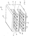
- Figure 1 is a front perspective showing of the compact shielded data connector assembly of the present invention.
- Figure 2 is a side-plan view of the connector assembly of Figure 1.
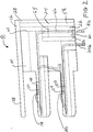
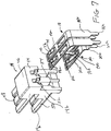
- Figure 3 shows, in exploded perspective view, components of the connector assembly of Figures 1 and 2.
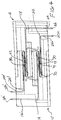
- Figure 4 shows an electrical connector of Figure 1 interconnected with a like connector in hermaphroditic fashion.
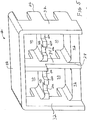
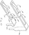
- Figure 5 is a rear-perspective view of the outer housing of the connector assembly of Figure 1.
- Figures 6 and 7 are, respectively, exploded front and rear perspective views of the insulative support member and electrical contacts of the connector assembly of Figure 1.
- Figure 8 is a perspective showing of alternative constructions of the electrical contacts of the connector assembly of Figure 1.
- Figure 9 is a side-plan view of the alternative contacts of Figure 8 supported within the terminal support member.
- Figure 10 is a perspective showing of an additional electrical contact design useful in the connector of the present invention.
- Figure 11 is a side-plan view of the contacts of Figure 10 supported within an insulative housing.
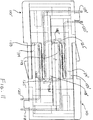
- Figure 12 shows in exploded perspective view the contacts of Figure 6 supported in a vertically stacked pair of insulative support members.
- Data connector assembly 10 is of the type used to transmit data signals between components of a closed-loop data system.
- Connector assembly 10 may function in hermaphroditic fashion, that is, it is interconnectable to a similarly formed electrical connector assembly, or it may function in a panel mount environment where plural such connector assemblies are supported on a wiring panel for connection with similarly formed electrical connectors.
- the connector assembly 10 of the present invention may be of the type shown and described in our application EP-A-0610087 entitled VERTICALLY ALIGNED ELECTRICAL CONNECTOR COMPONENTS; which is incorporated by reference herein for all purposes.
- Connector assembly 10 comprises an electrically conductive outer housing 12, a pair of side by side electrically insulative support members 14 and 16, upper and lower electrical contacts 18 and 20, respectively, an insulative rear-contact support 22 and a rear-conductive shield 24.
- Conductive outer housing 12 and conductive rear shield 24 are formed in the preferred embodiment of die-cast metal. However, other conductive elements such as conductive plastic or metalized plastic may be employed. Support members 14 and 16, as well as contact support 22, are formed of a suitably electrically insulative plastic. Electrical contacts 18 and 20 are formed of a suitably conductive metallic material such as beryllium copper.
- Outer housing 12 is generally an elongate rectangular member having a front interconnection end 26 and a rear contact accommodating end 28. Outer housing 12 is divided into four discrete compartments 30 arranged in side by side and upper and lower quadrants. Outer housing 12 includes a pair of opposed spaced-apart vertical side walls 32 and a central vertical dividing wall 34. A horizontal upper wall 38 extends across the upper extents of side walls 32 and dividing wall 34.
- Outer housing 12 further includes intermediate horizontal bridge portions 40 extending between side walls 32 and dividing wall 34, as well as lower horizontal bridge portions 42, which also extend between side walls 32 and dividing wall 34.
- the construction of outer housing 12 provides for the complete perimetrical bounding of compartments 30. It is contemplated that in the preferred embodiment, the outer housing 12 will be integrally formed. However, individual components may be used to make up outer housing 12.
- Support members 14 and 16 are preferably of identical construction.
- Support member 14 is generally an elongate molded plastic member having a rear contact accommodating end 44, a central main body portion 46 and upper and lower support platforms 48 and 50 extending oppositely from rear contact accommodating end 44.
- Support member 14 includes a pair of side by side upper channels 52 extending from rear contact accommodating end 44 through central main body portion 46 and along upper support platform 48.
- side by side lower channels 54 extend from the rear contact accommodating end 44 through central main body portion 46 and along lower support platform 50.
- Each support member 14 is divided into individual upper and lower stacked support elements 14a and 14b which include upper and lower support platforms 48 and 50, respectively. While support member 14 is shown to be integral, it is contemplated that the support member may comprise separate upper and lower support elements.
- Support members 14 and 16 are shown to be side by side, each having upper and lower support platforms 48 and 50. However, other constructions of the terminal support members are contemplated. Referring to Figure 12, the terminal support members may be formed to be vertically stacked upper and lower support members 70 and 72. Each of the support members 70 and 72 is formed of insulative plastic and respectively support contacts 18 and 20. Upper support member 70 includes a terminal support platform 74 while lower support member 72 includes a terminal support platform 76. Terminal support members 70 and 72 are configured to be received within conductive outer housing 12 (Fig. 5) which shields the individual contacts 18 and 20 supported therein as will be described in further detail hereinbelow.
- Lower contacts 20 include a generally elongate base portion 20a, a pin-type solder tail 20b and a reversely directed cantilevered spring portion 20c which extends back over base portion 20a.
- Solder tail 20b is of conventional construction and may be inserted into a through hole of a printed circuit board (not shown) and soldered thereto establishing electrical connection therebetween. In the present illustrative embodiment, solder tail 20b is shown extending downwardly at a right angle from base portion 20a, however, straight-solder tails may also be employed.
- Cantilevered spring portion 20c is constructed so as to be deflectable for movement toward and away from base portion 20a upon interconnection of a further connection device.
- Cantilevered spring portion 20c has an extended beam length which extends toward solder tail 20b.
- Upper contacts 18 are of construction similar to that of contacts 20.
- Contacts 18 include an elongate base portion 18a, a solder tail 18b and a reversely directed cantilevered spring portion 18c of length shorter than cantilevered spring portion 20c of contact 20.
- solder tail 18b of contacts 18 are longer than the solder tails 20b of contacts 20 so that the distal extents 18h and 20h of the solder tails extend approximately the same distance, facilitating connection of the solder tails to a printed circuit board.
- upper contacts 18 include a depending shunt member 18d which is struck from a central extent of planar base portion 18a.
- the distal extent 18e of shunt member 18d is engagable with the extended beam of cantilevered spring portion 20c of contacts 20 to provide for shunted engagement as between contacts 18 and 20.
- Shunt member 18d of contact 18 extends downwardly from base portion 18a at an angle just less than 90°.
- the distal extent 18e has a reversely curved portion.
- contacts 18 and 20 are supported within support member 14.
- Base portions 18a and 20a are supported respectively on platforms 48 and 50 through upper and lower channels 52 and 54.
- Solder tails 18b and 20b extend along rear contact accommodating end 44 of support member 14.
- Support members 14 and 16 supporting upper and lower contacts 18 and 20 are inserted into outer housing 12 in side by side fashion.
- Each upper and lower support platform 48 and 50 of support members 14 and 16 are individually accommodated in one of the bounded compartments 30 of outer housing 12 (Fig. 5).
- Upper wall 38, side walls 32 and lower bridge portions 42 serve to shield collectively the contact 18 and 20.
- Dividing wall 34 serves to shield each of the side by side pairs of contacts 18 and 20.
- Intermediate bridge portions 40 serve to shield the upper contacts 18 from the lower contacts 20.
- intermediate bridge portion 40 includes spaced recesses 40a separated by a central protrusion 40b.
- Shunt member 18d of each contact 18 extends through recess 40a.
- the central protrusion 40b provides shielding as between adjacent shunt member 18d.
- Shield 24 formed of conductive metal, includes a short forward wall 56 and a taller rear wall 58 separated by a centrally located transverse web 60. Shield 24 provides conductive shielding as between solder tails 18b of upper contacts 18 and solder tails 20b of lower contacts 20. This is achieved by positioning solder tail 20b on one side of forward wall 56 while solder tails 18b are positioned on the other side of forward wall 56. Solder tails 18b reside between walls 56 and 58.
- connector assembly 10 includes insulative contact support 22.
- Contact support 22 is a plastic member having a front wall 62, a taller rear wall 64 and individual chambers 66, which individually accommodate solder tails 18b of contacts 18.
- Contact support 22 includes a recess 68 extending from a lower edge thereof which accommodates web 60 of shield 24 when contact support 22 is inserted within shield 24.
- shield 24 having contact support 22 inserted therein, may be inserted over the solder tails 18b of contacts 18 to reside adjacent contact accommodating end 28 of outer housing 12.
- connector assembly 10 is shown interconnected to an identical connector 10' in hermaphroditic fashion. This is accomplished by rotating connector assembly 10' 180° and interconnecting the two parts so that upper contacts 18 of connector assembly 10 engage lower contacts 20' of connector assembly 10', while lower contacts 20 of connector assembly 10 engage upper contacts 18' of connector assembly 10'. It is noted that as the lower contacts of one connector engage the upper contacts of the other connector when connected in hermaphroditic fashion, the electrical path between each pair of the mated contacts will be the same for all contact pairs.
- Cantilevered spring portions 18c and 20c of upper and lower contacts 18 and 20 further provide a first upwardly inclined contact surface 70 extending from the front end of the contacts to a centrally located apex 72.
- the contact further includes a depending rearwardly facing engagement surface 74 extending from apex 72 down to the distal end of the contacts.
- FIGs 8 an 9 Further embodiments of the present invention may be shown in Figures 8 an 9. Contacts of the present invention include solder type tails 18b and 20b such as shown in contacts 18 and 20 for attachment to through holes of a printed circuit board. However, the present invention also contemplates employing other contact types 76 and 78, which include IDC portions 76a and 78a for making insulation displacing connection to electrical conductors (not shown) in a manner described in the above-incorporated patent application. IDC portions 76a and 78a may extend at oppositely directed 90° angles from the central base portions 76b and 78b of contacts 76 and 78. Figure 9 shows such insulation displacement contacts 76 and 78 supported in a support member 14.
- connector assembly 10 of the present invention may accommodate different transmission styles within the same connector assembly. While the present embodiment shows transmission terminal devices of the electrical signal type, other terminals, such as fiber optic terminations and power contacts, may be inserted into connector assembly 10. It is further contemplated that the transmission terminal device may be the stamped end of a co-axial cable where the center conductor serves as an electrical contact. Support members 14 and 16 can be adapted to accommodate such co-axial cable. Thus, connector assembly 10 may house mixed transmission components.
- Lower contact 120 includes a generally elongate base portion 120a, a pin-type solder tail 120b and a reversely directed cantilevered spring portion 120c, which extends back towards base portion 120a.
- Tail 120b and reversely bent cantilevered spring portion 120c function in a manner similar to that described above with respect to contact 20.
- Cantilevered spring portion 120c has a shorter extent than cantilevered spring portion 20c of contact 20.
- Upper contact 118 includes an elongate base 118a, a solder tail 118b and a reversely directed cantilevered spring portion 118c.
- upper contact 118 includes a depending shunt member 118d, which is struck from a central extent of planar base portion 118a.
- shunt member 118d is formed to be a deflectable cantilevered beam which deflects from the position shown in Figure 10 to a position upwardly toward base portion 118a.
- shunt member 118d is deflectable upon hermaphroditic mating connection of the connectors housing contacts 118.
- contact 120 includes an upwardly extending protrusion 120d, forming an engagement surface for shunt member 118d.
- Protrusion 120d is struck from a central extent of planar base portion 120a.
- Protrusion 120d has a distal extent 120e, which is engagable with a distal extent 118e of shunt member 118d. This engagement establishes electrical connection between contact 118 and contact 120.
- Shunt member 118d is deflectably movable away from protrusion 120d to break the connection between contacts 118 and 120.
- connector assemblies 110 and 110' include the contacts 118 and 120 shown in Figure 10.
- connection may be accomplished by rotating connector assembly 110' 180° and interconnecting the two components so that the upper contacts 118 of connector assembly 110 engage lower contacts 120' of connector assembly 110', while lower contacts 120 of connector assembly 110 engage upper contacts 118' of connector assembly 110'. The connection is achieved in a manner shown and described above with respect to Figure 4.
- the insulative housing 114 supporting contacts 118 and 120 includes upper and lower platforms 148 and 150 respectively.
- a forward end of upper platform 148 includes a shunt member deflection portion 125.
- Shunt member deflection portion 125 extends beyond the forward end of upper platform 148 so as to engage shunt member 118d' of corresponding connector 110'.
- shunt member deflection portion 125 contacts and engages shunt member 118d' of contact 118' deflecting it back away from protrusion 120d' to break the shunted electrical engagement between the components.
- shunt member deflection portion 125' of connector assembly 110' engages shunt member 118d, breaking its shunted connection with protrusion 120d.
Landscapes
- Physics & Mathematics (AREA)
- General Physics & Mathematics (AREA)
- Optics & Photonics (AREA)
- Details Of Connecting Devices For Male And Female Coupling (AREA)
- Coupling Device And Connection With Printed Circuit (AREA)
Applications Claiming Priority (2)
| Application Number | Priority Date | Filing Date | Title |
|---|---|---|---|
| US11455493A | 1993-08-30 | 1993-08-30 | |
| US114554 | 1993-08-30 |
Publications (3)
| Publication Number | Publication Date |
|---|---|
| EP0641043A2 true EP0641043A2 (de) | 1995-03-01 |
| EP0641043A3 EP0641043A3 (de) | 1995-11-15 |
| EP0641043B1 EP0641043B1 (de) | 2002-05-02 |
Family
ID=22355973
Family Applications (1)
| Application Number | Title | Priority Date | Filing Date |
|---|---|---|---|
| EP94306303A Expired - Lifetime EP0641043B1 (de) | 1993-08-30 | 1994-08-26 | Abgeschirmter kompakter Datenverbinder |
Country Status (7)
| Country | Link |
|---|---|
| EP (1) | EP0641043B1 (de) |
| JP (1) | JP2647349B2 (de) |
| CA (1) | CA2130216C (de) |
| DE (1) | DE69430505T2 (de) |
| ES (1) | ES2179062T3 (de) |
| IL (1) | IL110814A (de) |
| SG (1) | SG49262A1 (de) |
Cited By (4)
| Publication number | Priority date | Publication date | Assignee | Title |
|---|---|---|---|---|
| EP0827239A3 (de) * | 1996-08-30 | 1999-10-27 | Berg Electronics Manufacturing B.V. | Buchse mit integriertem Detektor |
| EP0968545A4 (de) * | 1998-01-19 | 2003-06-25 | Siemon Co | Verkabelungsverbindung mit hoher leistung |
| EP2169775A1 (de) * | 2008-09-24 | 2010-03-31 | Harting Electronics GmbH & Co. KG | Symmetrischer elektrischer Kontakt |
| WO2012039761A1 (en) * | 2010-09-20 | 2012-03-29 | Tyco Electronics Corporation | Connectors for e-textiles |
Families Citing this family (3)
| Publication number | Priority date | Publication date | Assignee | Title |
|---|---|---|---|---|
| JP2017073214A (ja) * | 2015-10-05 | 2017-04-13 | 日本圧着端子製造株式会社 | コネクタ |
| CN111009773B (zh) * | 2019-12-10 | 2020-11-13 | 中国矿业大学(北京) | 电缆连接器及电缆装置 |
| DE102020133324A1 (de) | 2020-12-14 | 2022-06-15 | Harting Electric Gmbh & Co. Kg | Leiterkartensteckverbinder mit hermaphroditischen Kontaktelementen |
Family Cites Families (7)
| Publication number | Priority date | Publication date | Assignee | Title |
|---|---|---|---|---|
| US4449778A (en) * | 1982-12-22 | 1984-05-22 | Amp Incorporated | Shielded electrical connector |
| IE55318B1 (en) * | 1982-12-22 | 1990-08-01 | Amp Inc | Shunt-protected electrical connector |
| US4582376A (en) * | 1984-04-09 | 1986-04-15 | Amp Incorporated | Shorting bar having wiping action |
| US4602833A (en) * | 1984-12-20 | 1986-07-29 | Amp Incorporated | Closed loop connector |
| US4744769A (en) * | 1984-12-20 | 1988-05-17 | Amp Incorporated | Closed loop connector |
| US5052940A (en) * | 1990-05-11 | 1991-10-01 | Rit-Rad Interconnection Technologies Ltd. | Hermaphroditic self-shorting electrical connector |
| JPH0425175U (de) * | 1990-06-25 | 1992-02-28 |
-
1994
- 1994-08-09 CA CA002130216A patent/CA2130216C/en not_active Expired - Lifetime
- 1994-08-26 SG SG1996008509A patent/SG49262A1/en unknown
- 1994-08-26 DE DE69430505T patent/DE69430505T2/de not_active Expired - Lifetime
- 1994-08-26 EP EP94306303A patent/EP0641043B1/de not_active Expired - Lifetime
- 1994-08-26 ES ES94306303T patent/ES2179062T3/es not_active Expired - Lifetime
- 1994-08-29 IL IL11081494A patent/IL110814A/en not_active IP Right Cessation
- 1994-08-30 JP JP6205200A patent/JP2647349B2/ja not_active Expired - Lifetime
Cited By (7)
| Publication number | Priority date | Publication date | Assignee | Title |
|---|---|---|---|---|
| EP0827239A3 (de) * | 1996-08-30 | 1999-10-27 | Berg Electronics Manufacturing B.V. | Buchse mit integriertem Detektor |
| US6095837A (en) * | 1996-08-30 | 2000-08-01 | Berg Technology, Inc. | Electrical connector with integral sensor device |
| EP0968545A4 (de) * | 1998-01-19 | 2003-06-25 | Siemon Co | Verkabelungsverbindung mit hoher leistung |
| EP2169775A1 (de) * | 2008-09-24 | 2010-03-31 | Harting Electronics GmbH & Co. KG | Symmetrischer elektrischer Kontakt |
| US7938696B2 (en) | 2008-09-24 | 2011-05-10 | Harting Electronics Gmbh & Co. Kg | Symmetrical electric contact |
| WO2012039761A1 (en) * | 2010-09-20 | 2012-03-29 | Tyco Electronics Corporation | Connectors for e-textiles |
| US8376759B2 (en) | 2010-09-20 | 2013-02-19 | Tyco Electronics Corporation | Connectors for E-textiles |
Also Published As
| Publication number | Publication date |
|---|---|
| ES2179062T3 (es) | 2003-01-16 |
| IL110814A (en) | 1998-10-30 |
| DE69430505T2 (de) | 2002-10-31 |
| CA2130216A1 (en) | 1995-03-01 |
| EP0641043A3 (de) | 1995-11-15 |
| JPH07192818A (ja) | 1995-07-28 |
| EP0641043B1 (de) | 2002-05-02 |
| IL110814A0 (en) | 1994-11-11 |
| SG49262A1 (en) | 1998-05-18 |
| CA2130216C (en) | 2004-10-26 |
| DE69430505D1 (de) | 2002-06-06 |
| JP2647349B2 (ja) | 1997-08-27 |
Similar Documents
| Publication | Publication Date | Title |
|---|---|---|
| EP0634817B1 (de) | Abgeschirmter kompakter Verbinder zur Datenübertragung | |
| EP0735612B1 (de) | Elektrischer Verbinder mit verbesserter Leiterhalterung und Schirmung | |
| US5564949A (en) | Shielded compact data connector | |
| CA2262727C (en) | Low crosstalk connector configuration | |
| US5344327A (en) | Electrical connectors | |
| US7104843B2 (en) | Receptacle | |
| US5865646A (en) | Connector shield with integral latching and ground structure | |
| US5380223A (en) | High density electrical connector | |
| KR910002264B1 (ko) | 다수의 전기 도체를 위한 종단기(terminator)와 그 중단기용 하우징 | |
| US5971812A (en) | Modular plug having a circuit board | |
| EP0624928B1 (de) | Abgeschirmte elektrische Verbinderanordnung | |
| US4537459A (en) | Jack for EMI/RFI shield terminating modular plug connector | |
| US5030121A (en) | Electrical connector with contact wiping action | |
| US4874333A (en) | Shunted modular electrical connector | |
| EP0641043B1 (de) | Abgeschirmter kompakter Datenverbinder | |
| US5531606A (en) | Shielded vertically aligned electrical connector components | |
| CA2114905C (en) | Vertically aligned electrical connector components | |
| US5556307A (en) | Modular telecommunication jack assembly | |
| US4506940A (en) | Input/output intercard connector | |
| US20260121352A1 (en) | Cable assembly and cable bypass assembly having the same |
Legal Events
| Date | Code | Title | Description |
|---|---|---|---|
| PUAI | Public reference made under article 153(3) epc to a published international application that has entered the european phase |
Free format text: ORIGINAL CODE: 0009012 |
|
| AK | Designated contracting states |
Kind code of ref document: A2 Designated state(s): BE CH DE ES FR GB IT LI LU NL SE |
|
| PUAL | Search report despatched |
Free format text: ORIGINAL CODE: 0009013 |
|
| AK | Designated contracting states |
Kind code of ref document: A3 Designated state(s): BE CH DE ES FR GB IT LI LU NL SE |
|
| 17P | Request for examination filed |
Effective date: 19960506 |
|
| 17Q | First examination report despatched |
Effective date: 19971105 |
|
| GRAG | Despatch of communication of intention to grant |
Free format text: ORIGINAL CODE: EPIDOS AGRA |
|
| GRAG | Despatch of communication of intention to grant |
Free format text: ORIGINAL CODE: EPIDOS AGRA |
|
| GRAH | Despatch of communication of intention to grant a patent |
Free format text: ORIGINAL CODE: EPIDOS IGRA |
|
| GRAH | Despatch of communication of intention to grant a patent |
Free format text: ORIGINAL CODE: EPIDOS IGRA |
|
| REG | Reference to a national code |
Ref country code: GB Ref legal event code: IF02 |
|
| RAP1 | Party data changed (applicant data changed or rights of an application transferred) |
Owner name: THOMAS & BETTS CORPORATION (A TENNESSEE CORPORATIO |
|
| RAP1 | Party data changed (applicant data changed or rights of an application transferred) |
Owner name: THOMAS & BETTS CORPORATION (A TENNESSEE CORPORATIO |
|
| GRAA | (expected) grant |
Free format text: ORIGINAL CODE: 0009210 |
|
| AK | Designated contracting states |
Kind code of ref document: B1 Designated state(s): BE CH DE ES FR GB IT LI LU NL SE |
|
| PG25 | Lapsed in a contracting state [announced via postgrant information from national office to epo] |
Ref country code: NL Free format text: LAPSE BECAUSE OF FAILURE TO SUBMIT A TRANSLATION OF THE DESCRIPTION OR TO PAY THE FEE WITHIN THE PRESCRIBED TIME-LIMIT Effective date: 20020502 Ref country code: LI Free format text: LAPSE BECAUSE OF FAILURE TO SUBMIT A TRANSLATION OF THE DESCRIPTION OR TO PAY THE FEE WITHIN THE PRESCRIBED TIME-LIMIT Effective date: 20020502 Ref country code: CH Free format text: LAPSE BECAUSE OF FAILURE TO SUBMIT A TRANSLATION OF THE DESCRIPTION OR TO PAY THE FEE WITHIN THE PRESCRIBED TIME-LIMIT Effective date: 20020502 Ref country code: BE Free format text: LAPSE BECAUSE OF FAILURE TO SUBMIT A TRANSLATION OF THE DESCRIPTION OR TO PAY THE FEE WITHIN THE PRESCRIBED TIME-LIMIT Effective date: 20020502 |
|
| REG | Reference to a national code |
Ref country code: GB Ref legal event code: FG4D |
|
| REG | Reference to a national code |
Ref country code: CH Ref legal event code: EP |
|
| REF | Corresponds to: |
Ref document number: 69430505 Country of ref document: DE Date of ref document: 20020606 |
|
| PGFP | Annual fee paid to national office [announced via postgrant information from national office to epo] |
Ref country code: SE Payment date: 20020801 Year of fee payment: 9 |
|
| PG25 | Lapsed in a contracting state [announced via postgrant information from national office to epo] |
Ref country code: SE Free format text: LAPSE BECAUSE OF FAILURE TO SUBMIT A TRANSLATION OF THE DESCRIPTION OR TO PAY THE FEE WITHIN THE PRESCRIBED TIME-LIMIT Effective date: 20020802 |
|
| NLV1 | Nl: lapsed or annulled due to failure to fulfill the requirements of art. 29p and 29m of the patents act | ||
| ET | Fr: translation filed | ||
| REG | Reference to a national code |
Ref country code: CH Ref legal event code: PL |
|
| REG | Reference to a national code |
Ref country code: ES Ref legal event code: FG2A Ref document number: 2179062 Country of ref document: ES Kind code of ref document: T3 |
|
| PLBE | No opposition filed within time limit |
Free format text: ORIGINAL CODE: 0009261 |
|
| STAA | Information on the status of an ep patent application or granted ep patent |
Free format text: STATUS: NO OPPOSITION FILED WITHIN TIME LIMIT |
|
| 26N | No opposition filed |
Effective date: 20030204 |
|
| PGFP | Annual fee paid to national office [announced via postgrant information from national office to epo] |
Ref country code: DE Payment date: 20130828 Year of fee payment: 20 Ref country code: LU Payment date: 20130906 Year of fee payment: 20 Ref country code: ES Payment date: 20130826 Year of fee payment: 20 |
|
| PGFP | Annual fee paid to national office [announced via postgrant information from national office to epo] |
Ref country code: GB Payment date: 20130827 Year of fee payment: 20 Ref country code: FR Payment date: 20130819 Year of fee payment: 20 |
|
| PGFP | Annual fee paid to national office [announced via postgrant information from national office to epo] |
Ref country code: IT Payment date: 20130823 Year of fee payment: 20 |
|
| REG | Reference to a national code |
Ref country code: DE Ref legal event code: R071 Ref document number: 69430505 Country of ref document: DE |
|
| REG | Reference to a national code |
Ref country code: GB Ref legal event code: PE20 Expiry date: 20140825 |
|
| PG25 | Lapsed in a contracting state [announced via postgrant information from national office to epo] |
Ref country code: DE Free format text: LAPSE BECAUSE OF EXPIRATION OF PROTECTION Effective date: 20140827 |
|
| PG25 | Lapsed in a contracting state [announced via postgrant information from national office to epo] |
Ref country code: GB Free format text: LAPSE BECAUSE OF EXPIRATION OF PROTECTION Effective date: 20140825 |
|
| REG | Reference to a national code |
Ref country code: ES Ref legal event code: FD2A Effective date: 20150107 |
|
| PG25 | Lapsed in a contracting state [announced via postgrant information from national office to epo] |
Ref country code: ES Free format text: LAPSE BECAUSE OF EXPIRATION OF PROTECTION Effective date: 20140827 |