EP0641131A2 - Méthode et appareil pour transmission et/ou récéption sériale de signaux multipléxés - Google Patents
Méthode et appareil pour transmission et/ou récéption sériale de signaux multipléxés Download PDFInfo
- Publication number
- EP0641131A2 EP0641131A2 EP94113152A EP94113152A EP0641131A2 EP 0641131 A2 EP0641131 A2 EP 0641131A2 EP 94113152 A EP94113152 A EP 94113152A EP 94113152 A EP94113152 A EP 94113152A EP 0641131 A2 EP0641131 A2 EP 0641131A2
- Authority
- EP
- European Patent Office
- Prior art keywords
- signal
- clock
- word
- circuit
- data
- Prior art date
- Legal status (The legal status is an assumption and is not a legal conclusion. Google has not performed a legal analysis and makes no representation as to the accuracy of the status listed.)
- Granted
Links
Images


Classifications
-
- H—ELECTRICITY
- H04—ELECTRIC COMMUNICATION TECHNIQUE
- H04J—MULTIPLEX COMMUNICATION
- H04J3/00—Time-division multiplex systems
- H04J3/02—Details
- H04J3/06—Synchronising arrangements
- H04J3/0635—Clock or time synchronisation in a network
-
- H—ELECTRICITY
- H04—ELECTRIC COMMUNICATION TECHNIQUE
- H04N—PICTORIAL COMMUNICATION, e.g. TELEVISION
- H04N21/00—Selective content distribution, e.g. interactive television or video on demand [VOD]
- H04N21/20—Servers specifically adapted for the distribution of content, e.g. VOD servers; Operations thereof
- H04N21/23—Processing of content or additional data; Elementary server operations; Server middleware
- H04N21/236—Assembling of a multiplex stream, e.g. transport stream, by combining a video stream with other content or additional data, e.g. inserting a URL [Uniform Resource Locator] into a video stream, multiplexing software data into a video stream; Remultiplexing of multiplex streams; Insertion of stuffing bits into the multiplex stream, e.g. to obtain a constant bit-rate; Assembling of a packetised elementary stream
- H04N21/2368—Multiplexing of audio and video streams
-
- H—ELECTRICITY
- H04—ELECTRIC COMMUNICATION TECHNIQUE
- H04N—PICTORIAL COMMUNICATION, e.g. TELEVISION
- H04N21/00—Selective content distribution, e.g. interactive television or video on demand [VOD]
- H04N21/20—Servers specifically adapted for the distribution of content, e.g. VOD servers; Operations thereof
- H04N21/23—Processing of content or additional data; Elementary server operations; Server middleware
- H04N21/242—Synchronisation processes, e.g. processing of PCR [Programme Clock References]
-
- H—ELECTRICITY
- H04—ELECTRIC COMMUNICATION TECHNIQUE
- H04N—PICTORIAL COMMUNICATION, e.g. TELEVISION
- H04N21/00—Selective content distribution, e.g. interactive television or video on demand [VOD]
- H04N21/40—Client devices specifically adapted for the reception of or interaction with content, e.g. set-top-box [STB]; Operations thereof
- H04N21/43—Processing of content or additional data, e.g. demultiplexing additional data from a digital video stream; Elementary client operations, e.g. monitoring of home network or synchronising decoder's clock; Client middleware
- H04N21/4302—Content synchronisation processes, e.g. decoder synchronisation
- H04N21/4305—Synchronising client clock from received content stream, e.g. locking decoder clock with encoder clock, extraction of the PCR packets
-
- H—ELECTRICITY
- H04—ELECTRIC COMMUNICATION TECHNIQUE
- H04N—PICTORIAL COMMUNICATION, e.g. TELEVISION
- H04N21/00—Selective content distribution, e.g. interactive television or video on demand [VOD]
- H04N21/40—Client devices specifically adapted for the reception of or interaction with content, e.g. set-top-box [STB]; Operations thereof
- H04N21/43—Processing of content or additional data, e.g. demultiplexing additional data from a digital video stream; Elementary client operations, e.g. monitoring of home network or synchronising decoder's clock; Client middleware
- H04N21/434—Disassembling of a multiplex stream, e.g. demultiplexing audio and video streams, extraction of additional data from a video stream; Remultiplexing of multiplex streams; Extraction or processing of SI; Disassembling of packetised elementary stream
- H04N21/4341—Demultiplexing of audio and video streams
-
- H—ELECTRICITY
- H04—ELECTRIC COMMUNICATION TECHNIQUE
- H04N—PICTORIAL COMMUNICATION, e.g. TELEVISION
- H04N7/00—Television systems
- H04N7/24—Systems for the transmission of television signals using pulse code modulation
- H04N7/52—Systems for transmission of a pulse code modulated video signal with one or more other pulse code modulated signals, e.g. an audio signal or a synchronizing signal
- H04N7/54—Systems for transmission of a pulse code modulated video signal with one or more other pulse code modulated signals, e.g. an audio signal or a synchronizing signal the signals being synchronous
- H04N7/56—Synchronising systems therefor
-
- H—ELECTRICITY
- H04—ELECTRIC COMMUNICATION TECHNIQUE
- H04J—MULTIPLEX COMMUNICATION
- H04J2203/00—Aspects of optical multiplex systems other than those covered by H04J14/05 and H04J14/07
- H04J2203/0001—Provisions for broadband connections in integrated services digital network using frames of the Optical Transport Network [OTN] or using synchronous transfer mode [STM], e.g. SONET, SDH
- H04J2203/0073—Services, e.g. multimedia, GOS, QOS
- H04J2203/008—Support of video
-
- H—ELECTRICITY
- H04—ELECTRIC COMMUNICATION TECHNIQUE
- H04J—MULTIPLEX COMMUNICATION
- H04J2203/00—Aspects of optical multiplex systems other than those covered by H04J14/05 and H04J14/07
- H04J2203/0001—Provisions for broadband connections in integrated services digital network using frames of the Optical Transport Network [OTN] or using synchronous transfer mode [STM], e.g. SONET, SDH
- H04J2203/0073—Services, e.g. multimedia, GOS, QOS
- H04J2203/0087—Support of voice
Definitions
- the present invention relates to a method and an apparatus for multiplexing, for example, a digital audio signal with a digital video signal by time division and transmitting and/or receiving such multiplexed signals as serial data, and more particularly, to a method and an apparatus capable of transmitting and/or receiving multiplexed signals even in a state where an audio signal is not synchronized with a video signal.
- serial digital interface For transmission of a digital video signal, there is known an exemplary system employing a serial digital interface. According to this interface, a digital video signal is transmitted as 1-bit serial data. More specifically, there is proposed in the serial digital interface a technique which utilizes that a blanking period of the video signal is rendered vacant due to non-transmission of horizontal and vertical sync signals, and transmits a digital audio signal together during such blanking period through time-base compression and multiplexing.
- serial digital interface mentioned above has a merit that both a digital video signal and a digital audio signal can be transmitted via a single coaxial cable without signal deterioration, whereby signal connection between digital video apparatus can be remarkably simplified.
- sampling clock frequencies for the digital video signal and the digital audio signal are different from each other.
- the sampling rate in the case of NTSC video signal is 14.3 MHz
- the rate for the audio signal is 48 kHz.
- the transmission clock rate for the audio signal is generally set to be equal to that for the digital video signal. Assuming in the above example that each sample is composed of 10 bits, it follows that the transmission rate is 143 Mbps.
- the audio data is compressed in its time base and is multiplexed to form data of the above transmission rate.
- any program employing a VTR there may be selected, depending on the content of a broadcast, a program play mode where the broadcast is so adjusted as to be completed within a changed time shorter or longer than a normal reproduction time. Supposing now that the time is shortened by 5 percent for example, the audio clock frequency is also shifted to be higher by 5 percent to consequently cause a non-locked state.
- a method for transmission of multiplexed signals as serial data obtained by multiplexing a first digital sample signal of a continuous signal with a second another digital sample signal comprises the steps of: generating an address based on a clock of the second another digital sample signal; sampling the generated address by the use of a sampling clock of the continuous signal; and transmitting the multiplexed signals inclusive of the sampled address value inserted therein.
- the above method further comprises the steps of: reproducing, from the received serial data on the reception side, a first clock synchronized with the transmission-side clock of the second another digital sample signal; generating address data on the basis of the reproduced clock; generating a second clock for reproduction of the continuous signal from both the generated address data and the address value separated from the received serial data; and reproducing the continuous signal in accordance with the generated second clock.
- the word clock of the second digital sample signal is equal to the word clock of the multiplexed signal.
- the continuous signal is an audio signal
- the second another digital sample signal is a digital video signal
- the sample signal of the audio signal is multiplexed during the blanking period of the digital video signal.
- an apparatus for transmission of multiplexed signals as serial data obtained by multiplexing a first digital sample signal of a continuous signal with a second another digital sample signal comprises: a circuit for generating an address based on a clock of the second another digital sample signal; a circuit for sampling the generated address by the use of a sampling clock of the continuous signal; a circuit for inserting the sampled address value into the multiplexed signals; and a circuit for converting the multiplexed signals, where the address value is inserted, into serial data for transmitting the same.
- the above apparatus further comprises: a circuit for separating, on a reception side, the received serial data into the first digital sample signal of the continuous signal, the second another digital sample signal and the address value; a circuit for reproducing a first clock synchronized with the clock of the second another digital sample signal; a circuit for generating address data on the basis of the reproduced clock; a comparator circuit for comparing the generated address data with the address value of the received multiplexed signal; a circuit for generating a second clock for reproduction of the continuous signal on the basis of the output of the comparator circuit; and a circuit for reproducing the continuous signal in accordance with the generated second clock.
- the word clock of the second another digital sample signal is equal to the word clock of the multiplexed signal.
- the continuous signal is an audio signal
- the second another digital sample signal is a digital video signal
- the sample signal of the audio signal is multiplexed during the blanking period of the digital video signal.
- an apparatus for transmitting and receiving multiplexed signals as serial data obtained by multiplexing a first digital sample signal of a continuous signal with a second another digital sample signal comprises: a circuit for generating a word address based on a word clock of the second another digital sample signal; a circuit for sampling the generated word address in accordance with the sampling clock of the continuous signal; a circuit for inserting the sampled word address value into the multiplexed signals; a circuit for converting the multiplexed signals, where the word address value is inserted, into serial data for transmitting the same; a circuit for separating the received serial data into the first digital sample signal of the continuous signal, the second another digital sample signal and the word address value; a circuit for reproducing the first word clock synchronized with the word clock of the second another digital sample signal; a circuit for generating address data on the basis of the reproduced word clock; a comparator circuit for comparing the generated word address data with the word address value of the received multiplexe
- the word clock of the second another digital sample signal is equal to the word clock of the multiplexed signal.
- the continuous signal is an audio signal
- the second another digital sample signal is a digital video signal
- the sample audio signal is multiplexed during the blanking period of the digital video signal.
- the word clock for the second another digital sample signal is reproduced in a synchronized state on the transmission and reception sides. And the address of the second another digital sample signal is generated on the basis of such word clock.
- the clock data relative to the multiplex continuous signal is transmitted in a state where the address value obtained by sampling the address of the second another sample signal in accordance with the audio clock is included in the multiplexed signals. Consequently the audio clock, which represents the time point of sampling the address in accordance with the audio clock, is reproduced from both the address data reproduced on the reception side and the data of the transmitted address value. Therefore, even if the multiplex continuous signal is not in synchronism with the second another sample signal, the clock for the continuous signal is properly reproducible on the reception side so that the continuous signal can be exactly reproduced.
- serial digital interface which transmits serial data of a multiplexed signals obtained by multiplexing a digital audio signal with a digital high-definition video signal.
- Fig. 1 is a block diagram showing exemplary constructions of transmission and reception sides in the embodiment.
- a word address ADRS of the digital video signal is generated in a word address generator 1 with reference to a horizontal sync signal of the high-definition video signal shown in Fig. 2A. More specifically, in the word address ADRS of the digital video signal, one horizontal interval is determined as its repetition period and, as shown in Fig. 2B for example, the top address of the horizontal sync signal is 0, and the last address of the effective video data is 4399.
- the digital video signal composed of respective words of the luminance signal Y and the color difference signals Pb, Pr is supplied to a video multiplexer 11 and is multiplexed in the order of Pb, Y, Pr, Y ... during the period of the video effective data shown in Fig. 2B, to be thereby formed into digital video data.
- the luminance signal and the color difference signals are distributed on the basis of the word address data ADRS.
- the horizontal sync signal of the video signal is not included in the transmitted data, and the video signal is the data except the blanking period.
- the blanking period corresponds to 560 words.
- the audio signal is converted into a digital audio signal AU composed of 24-bit words in accordance with an audio clock CKAU of, e.g., 48 kHz.
- the digital audio signal AU is written in an audio memory 12 in accordance with the audio clock CKAU.
- the audio data AU is read out from the audio memory 12 during the blanking period of the high-definition video signal in accordance with the word clock CKV of the video signal, and then the audio data is time-division multiplexed in an audio multiplexer 13 with the video data obtained from the video multiplexer 11. In this stage of the operation, the audio data is compressed by time division on the basis of the frequency difference between the write clock and the read clock.
- This embodiment is equipped with an audio clock data generator 16, to which the word address ADRS of the digital video data is inputted to be sampled in accordance with the audio clock CKAU.
- the word address ADRS of the video data is latched in accordance with the sampling clock CKAU of the audio data AU. And the value of the word address ADRS of the video data at the sampling time point of the latched audio word is supplied to the audio multiplexer 13 and then is inserted as data in the blanking period of the multiplexed data shown in Fig. 2B.
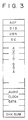
- Fig. 3 shows a format of the data to be multiplexed by time division as ancillary data (auxiliary data) during the blanking period.
- the first word "ADF” denotes an ancillary data flag which is used for identifying the data inserted in the blanking period, thereby indicating a start of the ancillary data.
- a next word “DID” denotes identification data signifying the kind of the ancillary data to make a discrimination as to whether the relevant ancillary data is audio data or some other data.
- a subsequent word “DBN” denotes a data block number which is serial in a packet during succession of audio data. And a jump of the number indicates a joint of the audio signal.
- DC data count
- audio data is inserted posterior to the data DC.
- the audio data is followed by the aforementioned audio clock data, i.e., the address data of the video data at the time point of the sample word of each digital audio signal.
- CHK SUM denotes a check sum covering from the data DID to the audio clock data and is used for error detection.
- the audio signal is multiplexed with the video signal as described, and further the address data of the video word is multiplexed as the clock data for the audio data to form multiplexed data, which is then supplied from the audio multiplexer 13 to a TRS multiplexer 14.
- TRS timing reference signal
- the output of the TRS multiplexer 14 is parallel data where each word is composed of 10 bits.
- the word clock for such parallel data is the one for high-definition video data.
- This parallel data is supplied to a parallel-to-serial converter 15, where the 10-bit parallel data of 148.5 MHz is converted into 1-bit serial data of 1.485 GHz.
- the data thus converted is outputted to a coaxial cable 30 and so forth, through which the multiplexed data is transmitted from the transmission side 10 to the reception side 20.
- a sync reproducer 22 including a data decision circuit 21 and a PLL circuit reproduces the serial data of 1.485 GHz and the bit clock from the received signal.
- a TRS detector/serial-to-parallel converter 23 in the next stage detects the timing reference signal (TRS) to reproduce the word sync signal and then converts the 1-bit serial data of 1.485 GHz into parallel data DT of 148.5 MHz where each word is composed of 10 bits.
- TRS timing reference signal
- the word address ADRS of the video data is reproduced from the word sync clock obtained from the sync reproducer 22.
- the parallel data DT is supplied from the converter 23 to a video reproducer 24, where the luminance signal Y and the color difference signals Pb, Pr are reproduced on the basis of the word address ADRS.
- the parallel data DT is supplied also to an audio memory 25, where the audio data in the blanking period is written and stored. Meanwhile the parallel data DT is further supplied to an audio clock reproducer 26, which then reproduces the word address corresponding to the timing of the audio clock in the blanking period.
- the audio clock reproducer 26 there is supplied the word address ADRS of the video data thus reproduced, so that the word address relative to the reproduced audio clock and the word address ADRS of the reproduced video data are compared with each other, and a clock pulse is obtained at the time of coincidence thereof. Then the clock pulse is supplied to, e.g., the PLL circuit to thereby reproduce the audio clock CKAU equal to the stable transmission-side clock. Subsequently the clock CKAU is supplied to the audio memory 25, from which the audio data is read out. Thus, the audio data can be read out without any excess or deficiency on the reception side to be thereby reproduced properly.
- Fig. 4 is a block diagram of the audio clock data generator 16 employed on the transmission side 10.
- the audio clock CKAU from the transmission side is supplied to a differentiator 161, where a differential pulse is obtained at the sampling time point corresponding to, e.g., the fall or trailing edge.
- the differential pulse thus obtained is then supplied to address latch circuits 162 and 163.
- the address latch circuits 162 and 163 are in cascade connection to serve as a shift register where an address value is transferred to the latter-stage latch circuit in response to each clock pulse.
- the word address ADRS of the digital video data at the timing of the audio clock CKAU are sequentially latched by the address latch circuits 162 and 163, and then are supplied via a selector 164 to the audio multiplexer 13, where the word address ADRS is inserted and multiplexed in the blanking period as mentioned.
- Fig. 5 is a block diagram showing an exemplary construction of the audio clock data reproducer 26 employed on the reception side 20.
- the parallel data DT outputted from the converter 23 is supplied to an audio clock data extractor 261, to which a word clock WCK is also supplied from the converter 23. Consequently the word address data of the video data relative to the audio clock inserted in the blanking period is extracted and then is held by address latch circuits 262 and 263.
- the address value of the video signal at the time point of each audio clock held by the address latch circuits 262 and 263 is supplied to coincidence detectors 264 and 265, which are also supplied with the word address signal ADRS of the reception-side digital video data. And upon coincidence between the word address data obtained from the latch circuits 262, 263 and the input word address data ADRS, coincidence detection pulses are generated from the coincidence detectors 263 and 265. Such pulses are supplied via an OR gate 266 to a PLL circuit 267 so that the audio clock CKAU is reproduced.
- the provision of such PLL circuit 267 is based on the following reason. Since the audio clock data is equal to the data obtained by sampling the original transmission-side audio clock CKAU in accordance with the video clock, the audio clock data includes some jitters of the video clock period (6.734 nsec). Consequently the clock pulse obtained via the OR gate 266 includes such jitter component. Therefore the PLL circuit 267 is employed to acquire a jitterless clock CKAU.
- a jitterless audio clock is generated through the PLL circuit 267 on the reception side so as to eliminate the jitter component caused by sampling the audio clock in accordance with the video clock.
- the jitter is permissible to some extent depending on the purpose of use. In such a case, therefore, the output of the OR gate 266 may be used directly as the audio clock.
- reception-side audio clock is generated by utilizing the address data of the video data relative to the audio clock multiplexed with the transmission data, there occurs neither excess nor deficiency of the data in the reception-side audio memory even if the audio clock on the transmission side is not in synchronism with the video signal, so that the audio signal can be reproduced properly without any disadvantage.
- the audio signal is not limited to one channel alone, and signals of two or more channels may be transmitted within a range of the blanking period during which multiplexing is performed.
- the audio clock frequency is set to 48 kHz as an example
- any other adequate frequency is applicable as well.
- the video signal described as an example is the one based on a 1125/60 high-definition television system.
- the present invention is further applicable to a component video signal of a 525/60 or 625/50 system, or to a video signal of any other television system such as NTSC or PAL.
- the present invention is applicable to any multiplexed signals composed of a continuous signal and another signal.
- the embodiment mentioned above represents an example where the continuous signal is an audio signal while the other sample signal is a digital video signal, and the audio signal is multiplexed by utilizing the blanking period of the video signal. Therefore the word clock used for such multiplexing is equal to the word clock of the video data.
- the other sample signal is a continuous signal, its time base is compressed and a vacant period is prepared for multiplexing the continuous signal.
- the word clock of the other sample signal and the word clock used for multiplexing are different in frequency from each other. But if the word clock of the other sample signal is synchronously locked on both the transmission side and the reception side, the reception-side clock of the continuous signal can be reproduced in the same manner as mentioned by inclusively transmitting, together with the multiplexed signals, the address value obtained by sampling the address data, which is based on the word clock of the other sample signal, in accordance with the clock of the continuous signal. It is a matter of course that, in this case also, the address value obtained by sampling the address data, which is based on the word clock for multiplexing, in accordance with the clock of the continuous signal, may be included in the multiplexed signals so as to be transmitted therewith.
- the word address data of another signal reproducible on the reception side is sampled in accordance with the clock signal of the multiplex continuous signal, and the address data thus sampled is inserted into the multiplexed signals to be thereby transmitted together. Consequently, even if the continuous signal is not in synchronism with another signal on the transmission side, the clock of the continuous signal is accurately reproducible from the transmitted address data, whereby the continuous signal can be properly reproduced on the reception side.
Landscapes
- Engineering & Computer Science (AREA)
- Signal Processing (AREA)
- Multimedia (AREA)
- Computer Networks & Wireless Communication (AREA)
- Television Systems (AREA)
- Time-Division Multiplex Systems (AREA)
Applications Claiming Priority (2)
| Application Number | Priority Date | Filing Date | Title |
|---|---|---|---|
| JP23101993A JP3546889B2 (ja) | 1993-08-24 | 1993-08-24 | 多重化伝送方法および装置 |
| JP231019/93 | 1993-08-24 |
Publications (3)
| Publication Number | Publication Date |
|---|---|
| EP0641131A2 true EP0641131A2 (fr) | 1995-03-01 |
| EP0641131A3 EP0641131A3 (fr) | 1995-04-26 |
| EP0641131B1 EP0641131B1 (fr) | 1999-04-14 |
Family
ID=16916986
Family Applications (1)
| Application Number | Title | Priority Date | Filing Date |
|---|---|---|---|
| EP94113152A Expired - Lifetime EP0641131B1 (fr) | 1993-08-24 | 1994-08-23 | Méthode et appareil pour transmission et/ou récéption sériale de signaux multipléxés |
Country Status (5)
| Country | Link |
|---|---|
| US (1) | US5523795A (fr) |
| EP (1) | EP0641131B1 (fr) |
| JP (1) | JP3546889B2 (fr) |
| KR (1) | KR100322979B1 (fr) |
| DE (1) | DE69417823T2 (fr) |
Cited By (5)
| Publication number | Priority date | Publication date | Assignee | Title |
|---|---|---|---|---|
| WO1997001930A1 (fr) | 1995-06-28 | 1997-01-16 | Nextlevel Systems, Inc. | Transmission, a bonne occupation spectrale, de donnees utilisateur dans un flux de donnees de television numerique |
| EP0732853A3 (fr) * | 1995-03-16 | 1997-07-16 | Sony Corp | Transmission et réception de données |
| EP1011041A3 (fr) * | 1998-12-18 | 2000-10-18 | Matsushita Electric Industrial Co., Ltd. | Appareil de transfert de données, système de transfert de données et support d'enregistrement |
| US6553073B1 (en) | 1996-09-30 | 2003-04-22 | Sony Corporation | Sending device, receiving device, sending-receiving device, transmitter, and transmitting method |
| US7292610B2 (en) | 1996-07-04 | 2007-11-06 | Matsushita Electric Industrial Co., Ltd. | Multiplexed data producing apparatus, encoded data reproducing apparatus, clock conversion apparatus, encoded data recording medium, encoded data transmission medium, multiplexed data producing method, encoded data reproducing method, and clock conversion method |
Families Citing this family (37)
| Publication number | Priority date | Publication date | Assignee | Title |
|---|---|---|---|---|
| US6239794B1 (en) * | 1994-08-31 | 2001-05-29 | E Guide, Inc. | Method and system for simultaneously displaying a television program and information about the program |
| JP3541896B2 (ja) * | 1994-07-15 | 2004-07-14 | ソニー株式会社 | 情報信号編集装置及び編集システム |
| US6769128B1 (en) | 1995-06-07 | 2004-07-27 | United Video Properties, Inc. | Electronic television program guide schedule system and method with data feed access |
| US5835498A (en) * | 1995-10-05 | 1998-11-10 | Silicon Image, Inc. | System and method for sending multiple data signals over a serial link |
| JPH09212139A (ja) * | 1996-02-02 | 1997-08-15 | Sony Corp | 画像表示システム |
| US5940073A (en) | 1996-05-03 | 1999-08-17 | Starsight Telecast Inc. | Method and system for displaying other information in a TV program guide |
| US8635649B2 (en) | 1996-12-19 | 2014-01-21 | Gemstar Development Corporation | System and method for modifying advertisement responsive to EPG information |
| EP1036466B1 (fr) | 1997-07-21 | 2003-03-26 | E Guide, Inc. | Procede permettant de naviguer dans un guide de programmes de television avec des publicites |
| US20020095676A1 (en) | 1998-05-15 | 2002-07-18 | Robert A. Knee | Interactive television program guide system for determining user values for demographic categories |
| US6091742A (en) * | 1998-08-17 | 2000-07-18 | Gilant Satellite Networks Ltd. | Bi-directional communications protocol |
| US6898762B2 (en) | 1998-08-21 | 2005-05-24 | United Video Properties, Inc. | Client-server electronic program guide |
| JP2001274923A (ja) * | 2000-03-28 | 2001-10-05 | Nec Eng Ltd | 携帯電話伝送システム |
| US7110457B1 (en) * | 2000-05-09 | 2006-09-19 | Leitch Technology International Inc. | System and method for time division multiplexing of asynchronous video and data signals |
| US7161998B2 (en) * | 2001-01-24 | 2007-01-09 | Broadcom Corporation | Digital phase locked loop for regenerating the clock of an embedded signal |
| JP3903721B2 (ja) * | 2001-03-12 | 2007-04-11 | ソニー株式会社 | 情報送信装置および方法、情報受信装置および方法、情報送受信システムおよび方法、記録媒体およびプログラム |
| US7123673B2 (en) * | 2001-07-19 | 2006-10-17 | Visteon Global Technologies, Inc. | System and method for transmission of digital information of varying sample rates over a synchronous network |
| US7295578B1 (en) | 2001-09-12 | 2007-11-13 | Lyle James D | Method and apparatus for synchronizing auxiliary data and video data transmitted over a TMDS-like link |
| US7558326B1 (en) | 2001-09-12 | 2009-07-07 | Silicon Image, Inc. | Method and apparatus for sending auxiliary data on a TMDS-like link |
| US7257163B2 (en) * | 2001-09-12 | 2007-08-14 | Silicon Image, Inc. | Method and system for reducing inter-symbol interference effects in transmission over a serial link with mapping of each word in a cluster of received words to a single transmitted word |
| US7088398B1 (en) | 2001-12-24 | 2006-08-08 | Silicon Image, Inc. | Method and apparatus for regenerating a clock for auxiliary data transmitted over a serial link with video data |
| WO2003058946A2 (fr) * | 2001-12-24 | 2003-07-17 | Silicon Image, Inc. | Procede et systeme de transmission de donnees video et auxiliaires via une liaison serie |
| US7283566B2 (en) * | 2002-06-14 | 2007-10-16 | Silicon Image, Inc. | Method and circuit for generating time stamp data from an embedded-clock audio data stream and a video clock |
| US7965837B2 (en) * | 2003-04-30 | 2011-06-21 | Sony Corporation | Method and system for wireless digital video presentation |
| US7436504B2 (en) * | 2003-09-10 | 2008-10-14 | Shear Graphics, Llc | Non-destructive testing and imaging |
| US7562379B2 (en) * | 2003-12-22 | 2009-07-14 | Sony Corporation | Method and system for wireless digital multimedia presentation |
| US6897793B1 (en) | 2004-04-29 | 2005-05-24 | Silicon Image, Inc. | Method and apparatus for run length limited TMDS-like encoding of data |
| CN101036329B (zh) * | 2004-10-07 | 2011-06-08 | 汤姆逊许可公司 | 音频/视频路由器 |
| KR100719343B1 (ko) | 2005-02-28 | 2007-05-17 | 삼성전자주식회사 | 독립적인 클럭 소스를 기준으로 직렬 클럭을 생성하는 직렬변환기와 데이터의 직렬 전송 방법 |
| KR100766496B1 (ko) * | 2005-07-08 | 2007-10-15 | 삼성전자주식회사 | 에이치디엠아이 전송 시스템 |
| US8380726B2 (en) | 2006-03-06 | 2013-02-19 | Veveo, Inc. | Methods and systems for selecting and presenting content based on a comparison of preference signatures from multiple users |
| US8316394B2 (en) | 2006-03-24 | 2012-11-20 | United Video Properties, Inc. | Interactive media guidance application with intelligent navigation and display features |
| US8832742B2 (en) | 2006-10-06 | 2014-09-09 | United Video Properties, Inc. | Systems and methods for acquiring, categorizing and delivering media in interactive media guidance applications |
| US7801888B2 (en) | 2007-03-09 | 2010-09-21 | Microsoft Corporation | Media content search results ranked by popularity |
| JP4702402B2 (ja) * | 2008-06-05 | 2011-06-15 | ソニー株式会社 | 信号送信装置、信号送信方法、信号受信装置及び信号受信方法 |
| US9166714B2 (en) | 2009-09-11 | 2015-10-20 | Veveo, Inc. | Method of and system for presenting enriched video viewing analytics |
| US9736524B2 (en) | 2011-01-06 | 2017-08-15 | Veveo, Inc. | Methods of and systems for content search based on environment sampling |
| KR102533425B1 (ko) * | 2022-10-31 | 2023-05-30 | 한국에너지기술연구원 | 수소공급장치 및 수소공급방법 |
Citations (1)
| Publication number | Priority date | Publication date | Assignee | Title |
|---|---|---|---|---|
| US5199030A (en) | 1990-09-11 | 1993-03-30 | Sony Corporation | Digital signal transmission device |
Family Cites Families (12)
| Publication number | Priority date | Publication date | Assignee | Title |
|---|---|---|---|---|
| US3755624A (en) * | 1968-06-26 | 1973-08-28 | Communications Satellite Corp | Pcm-tv system using a unique word for horizontal time synchronization |
| US3988528A (en) * | 1972-09-04 | 1976-10-26 | Nippon Hoso Kyokai | Signal transmission system for transmitting a plurality of information signals through a plurality of transmission channels |
| JPS58100585A (ja) * | 1981-12-10 | 1983-06-15 | Nec Corp | 映音同時伝送方式 |
| US4544950A (en) * | 1984-01-03 | 1985-10-01 | At&T Bell Laboratories | Technique for the transmission of video and audio signals over a digital transmission system |
| GB8414665D0 (en) * | 1984-06-08 | 1984-07-11 | Philips Electronic Associated | Television transmission system |
| US5113242A (en) * | 1987-07-24 | 1992-05-12 | North American Philips Corporation | Two-line MAC high definition television system |
| DE3732111A1 (de) * | 1987-09-24 | 1989-04-06 | Bosch Gmbh Robert | Verfahren zur laufzeitanpassung von video- und audiosignalen an ein referenzsignal |
| US5231492A (en) * | 1989-03-16 | 1993-07-27 | Fujitsu Limited | Video and audio multiplex transmission system |
| US5138440A (en) * | 1990-10-29 | 1992-08-11 | General Instrument Corporation | Method and apparatus for communicating a plurality of asynchronous signals over a digital communication path |
| JPH04207883A (ja) * | 1990-11-30 | 1992-07-29 | Fujitsu Ltd | クロック同期方式 |
| US5287182A (en) * | 1992-07-02 | 1994-02-15 | At&T Bell Laboratories | Timing recovery for variable bit-rate video on asynchronous transfer mode (ATM) networks |
| EP0598295B1 (fr) * | 1992-11-17 | 1998-10-14 | Matsushita Electric Industrial Co., Ltd. | Appareils de multiplexage et de séparation des signaux vidéo et audio |
-
1993
- 1993-08-24 JP JP23101993A patent/JP3546889B2/ja not_active Expired - Lifetime
-
1994
- 1994-08-16 US US08/291,194 patent/US5523795A/en not_active Expired - Lifetime
- 1994-08-23 DE DE69417823T patent/DE69417823T2/de not_active Expired - Lifetime
- 1994-08-23 KR KR1019940020743A patent/KR100322979B1/ko not_active Expired - Lifetime
- 1994-08-23 EP EP94113152A patent/EP0641131B1/fr not_active Expired - Lifetime
Patent Citations (1)
| Publication number | Priority date | Publication date | Assignee | Title |
|---|---|---|---|---|
| US5199030A (en) | 1990-09-11 | 1993-03-30 | Sony Corporation | Digital signal transmission device |
Cited By (8)
| Publication number | Priority date | Publication date | Assignee | Title |
|---|---|---|---|---|
| EP0732853A3 (fr) * | 1995-03-16 | 1997-07-16 | Sony Corp | Transmission et réception de données |
| US5946307A (en) * | 1995-03-16 | 1999-08-31 | Sony Corporation | System for transmitting and receiving signals of serial data interface format and serial digital data interface format on the same path |
| WO1997001930A1 (fr) | 1995-06-28 | 1997-01-16 | Nextlevel Systems, Inc. | Transmission, a bonne occupation spectrale, de donnees utilisateur dans un flux de donnees de television numerique |
| US7292610B2 (en) | 1996-07-04 | 2007-11-06 | Matsushita Electric Industrial Co., Ltd. | Multiplexed data producing apparatus, encoded data reproducing apparatus, clock conversion apparatus, encoded data recording medium, encoded data transmission medium, multiplexed data producing method, encoded data reproducing method, and clock conversion method |
| EP0817502A3 (fr) * | 1996-07-04 | 2010-01-06 | Panasonic Corporation | Méthode de traitement de données vidéo multiplexées assurant la synchronisation de plusieurs objets de données |
| US6553073B1 (en) | 1996-09-30 | 2003-04-22 | Sony Corporation | Sending device, receiving device, sending-receiving device, transmitter, and transmitting method |
| EP1011041A3 (fr) * | 1998-12-18 | 2000-10-18 | Matsushita Electric Industrial Co., Ltd. | Appareil de transfert de données, système de transfert de données et support d'enregistrement |
| US6460095B1 (en) | 1998-12-18 | 2002-10-01 | Matsushita Electric Industrial Co., Ltd. | Data transfer apparatus, data transfer system and recording medium |
Also Published As
| Publication number | Publication date |
|---|---|
| EP0641131A3 (fr) | 1995-04-26 |
| JPH0767087A (ja) | 1995-03-10 |
| KR100322979B1 (ko) | 2002-06-20 |
| DE69417823D1 (de) | 1999-05-20 |
| EP0641131B1 (fr) | 1999-04-14 |
| DE69417823T2 (de) | 1999-08-12 |
| KR950007334A (ko) | 1995-03-21 |
| US5523795A (en) | 1996-06-04 |
| JP3546889B2 (ja) | 2004-07-28 |
Similar Documents
| Publication | Publication Date | Title |
|---|---|---|
| EP0641131B1 (fr) | Méthode et appareil pour transmission et/ou récéption sériale de signaux multipléxés | |
| EP1381235B1 (fr) | Procede d'emission de donnees, procede de reception de donnees, dispositif d'emission de donnees et dispositif de reception de donnees | |
| US8451385B2 (en) | Signal transmitter and signal receiver | |
| US20020174440A1 (en) | Video display apparatus, audio mixing apparatus, video-audio output apparatus and video-audio synchronizing method | |
| US20040252235A1 (en) | Data transmission device and data reception device | |
| US6618095B1 (en) | Serial digital interface system transmission/reception method and device therefor | |
| US5483538A (en) | Audio frame synchronization for embedded audio demultiplexers | |
| US5583574A (en) | Video-data transmitter, video-data receiver, and video-data transceiver for connecting parallel video-data into serial video-data and vice versa | |
| US6195393B1 (en) | HDTV video frame synchronizer that provides clean digital video without variable delay | |
| CA2224786C (fr) | Procede et dispositif pour la transmission de donnees supplementaires dans des canaux tv | |
| JP2002125207A (ja) | 信号送信装置及び信号受信装置 | |
| US5815630A (en) | Tape dubbing and copy guard signal inserting method and apparatus | |
| EP0518644A2 (fr) | Système de multiplexage pour un signal vidéo | |
| JP2950871B2 (ja) | 文字放送受信機の文字データ再生方法 | |
| JP2585317B2 (ja) | 時刻情報伝送方法とその受信装置 | |
| KR940008491B1 (ko) | 브이씨알의 재생방식 판별신호 삽입 및 검출장치 | |
| JPH07135578A (ja) | データ伝送システムにおける同期装置 | |
| JPH07203424A (ja) | 衛星放送字幕焼付けシステム | |
| EP0484144A2 (fr) | Procédés et dispositif de traitement d'un signal vidéo | |
| JPH11196393A (ja) | 信号伝送方法および装置、受信装置、記録媒体 | |
| JPH06276491A (ja) | 映像信号処理回路 | |
| JPH09297970A (ja) | ディジタル信号の雑音低減装置 | |
| JPS6059887A (ja) | カラ−テレビジヨン受信機 | |
| JPH09238305A (ja) | コピーガード発生装置 | |
| JPS61189793A (ja) | 画像情報記録再生装置 |
Legal Events
| Date | Code | Title | Description |
|---|---|---|---|
| PUAI | Public reference made under article 153(3) epc to a published international application that has entered the european phase |
Free format text: ORIGINAL CODE: 0009012 |
|
| AK | Designated contracting states |
Kind code of ref document: A2 Designated state(s): DE FR GB |
|
| PUAL | Search report despatched |
Free format text: ORIGINAL CODE: 0009013 |
|
| AK | Designated contracting states |
Kind code of ref document: A3 Designated state(s): DE FR GB |
|
| 17P | Request for examination filed |
Effective date: 19950928 |
|
| 17Q | First examination report despatched |
Effective date: 19970714 |
|
| GRAG | Despatch of communication of intention to grant |
Free format text: ORIGINAL CODE: EPIDOS AGRA |
|
| GRAG | Despatch of communication of intention to grant |
Free format text: ORIGINAL CODE: EPIDOS AGRA |
|
| GRAH | Despatch of communication of intention to grant a patent |
Free format text: ORIGINAL CODE: EPIDOS IGRA |
|
| GRAH | Despatch of communication of intention to grant a patent |
Free format text: ORIGINAL CODE: EPIDOS IGRA |
|
| GRAA | (expected) grant |
Free format text: ORIGINAL CODE: 0009210 |
|
| AK | Designated contracting states |
Kind code of ref document: B1 Designated state(s): DE FR GB |
|
| REF | Corresponds to: |
Ref document number: 69417823 Country of ref document: DE Date of ref document: 19990520 |
|
| ET | Fr: translation filed | ||
| PLBE | No opposition filed within time limit |
Free format text: ORIGINAL CODE: 0009261 |
|
| STAA | Information on the status of an ep patent application or granted ep patent |
Free format text: STATUS: NO OPPOSITION FILED WITHIN TIME LIMIT |
|
| 26N | No opposition filed | ||
| REG | Reference to a national code |
Ref country code: GB Ref legal event code: IF02 |
|
| PGFP | Annual fee paid to national office [announced via postgrant information from national office to epo] |
Ref country code: DE Payment date: 20130821 Year of fee payment: 20 |
|
| PGFP | Annual fee paid to national office [announced via postgrant information from national office to epo] |
Ref country code: GB Payment date: 20130821 Year of fee payment: 20 Ref country code: FR Payment date: 20130823 Year of fee payment: 20 |
|
| REG | Reference to a national code |
Ref country code: DE Ref legal event code: R071 Ref document number: 69417823 Country of ref document: DE |
|
| REG | Reference to a national code |
Ref country code: GB Ref legal event code: PE20 Expiry date: 20140822 |
|
| PG25 | Lapsed in a contracting state [announced via postgrant information from national office to epo] |
Ref country code: DE Free format text: LAPSE BECAUSE OF EXPIRATION OF PROTECTION Effective date: 20140826 |
|
| PG25 | Lapsed in a contracting state [announced via postgrant information from national office to epo] |
Ref country code: GB Free format text: LAPSE BECAUSE OF EXPIRATION OF PROTECTION Effective date: 20140822 |